

Page 1
IP8173H
Mini-box
Network Camera
Quick Installation Guide
繁中 日本語
English
Dansk
Indonesia
簡中
Français
Deutsch
Español Português
3MP • Compact Size • WDR Pro
Italiano
Türkçe
Polski
Русский
Česky Svenska
Nederlands
Page 2
Warning Before Installation
5
1
0
0
0
0
2
2
1
G
Power off the Network Camera as
soon as smoke or unusual odors are
detected.
Do not place the Network Camera
around heat sources, such as a
television or oven.
Keep the Network Camera away from
direct sunlight.
Do not place the Network Camera on
unsteady surfaces.
Do not disassemble the Network
Camera.
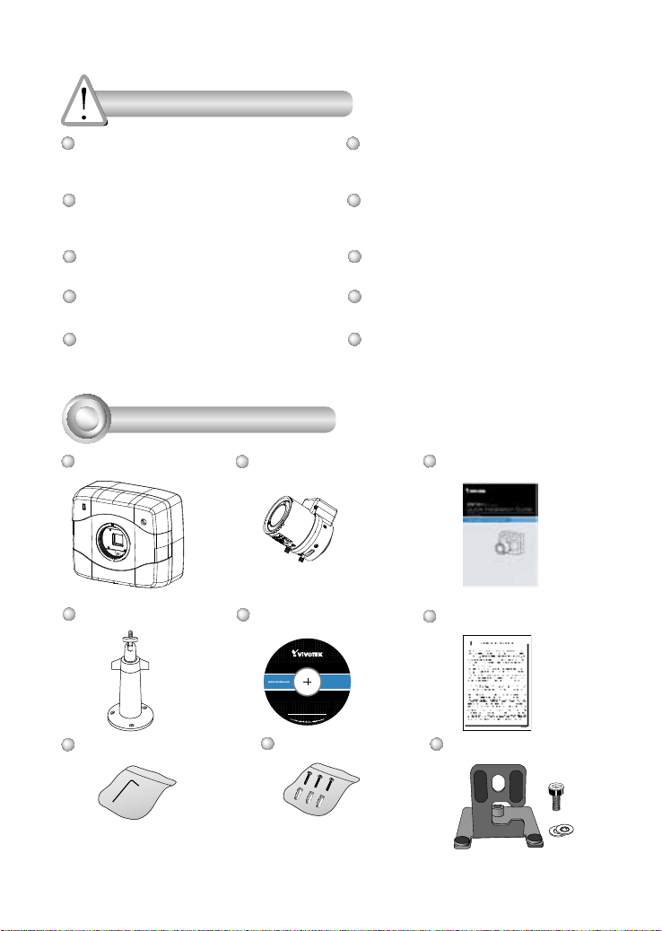
Package Contents
1
IP8173H
Camera Stand
CS-mount Lens
Software CD
Keep the Network Camera away
from water. If the Network Camera
becomes wet, power off immediately.
Refer to your user's manual for the
operating temperature.
Do not place the Network Camera in
high humidity environments.
Do not touch the Network Camera
during a lightning storm.
Do not drop the Network Camera.
Quick Installation Guide
Warranty Card
L-type Hex Key Wrench
Screws
Mount Bracket
Page 3
Physical Description
2
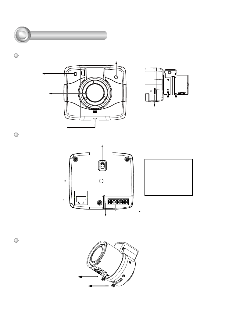
Front Panel
Status LED
Lens
Rear Panel
Mounting Hole
Ethernet 10/100
RJ45 Socket
Mount ring
adjustment
Light Sensor
Iris Control Cable Socket
Recessed Reset Button
Micro SD
MicroSD/SDHC/SDXC
Card Slot
1 2 3 4 5 6 7
RS485_N
RS485_P
GND
DI
AUDIO_OUT
GND_AUDIO
MIC_IN
General I/O Terminal
Block
Lens
Focus Controller
Zoom Controller
EN - 2
Page 4
Mounting the Lens to the Camera
3
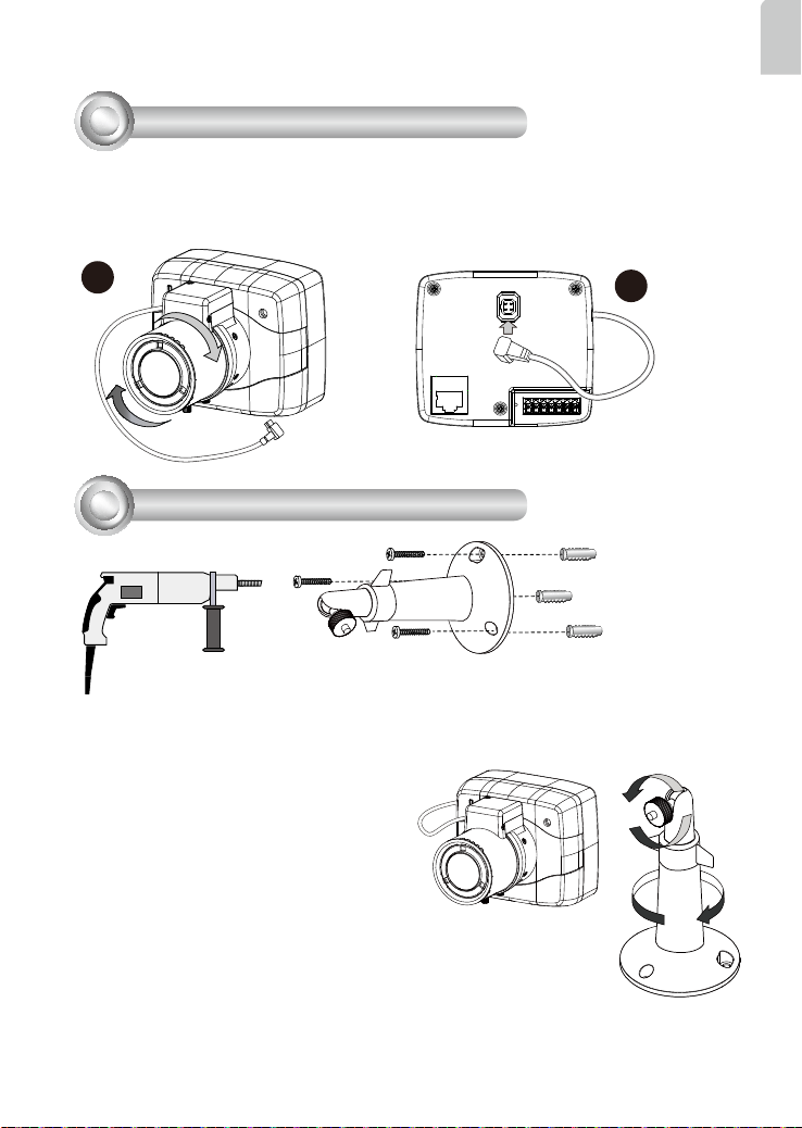
1. Mount the lens by turning it clockwise onto the camera mount until it stops.
2. Connect the iris control cable to the socket. Connect the iris control cable before
power-on. Otherwise, you will not be able to access the exposure related
settings.
English
1
Mounting the Camera to Stand
4
1. Use the holes on the camera stand to mark drill holes on the wall. Drill holes on your
preferred location.
2. Hammer in the included plastic anchors.
3. Install the camera stand to wall or ceiling
by driving screws through it.
4. Attach the camera to stand by turning
the stand and the fastening rings.
2
EN - 3
Page 5
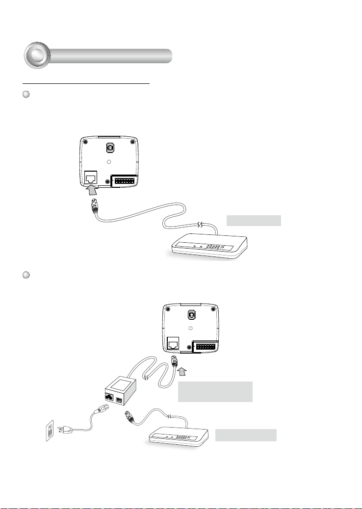
Network Deployment
5
Power over Ethernet (PoE)
When using a PoE-enabled switch
The Network Camera is PoE-compliant, allowing transmission of power and data via
a single Ethernet cable. Follow the below illustration to connect the Network Camera
to a PoE-enabled switch via Ethernet cable.
PoE Switch
POWER
LINK
COLLISION
RECEIVE
1
2
PARTITION
3
4
5
When using a non-PoE switch
Use a PoE power injector (optional) to connect between the Network Camera and a
non-PoE switch.
PoE Power Injector
(optional)
Non-PoE Switch
LINK
POWER
COLLISION
RECEIVE
1
2
PARTITION
3
4
5
EN - 4
Page 6
Assigning an IP Address
6
1. Install "Installation Wizard 2" from the Software Utility directory on the software CD.
2. The program will conduct an analysis of your network environment. After your network
is analyzed, please click on the "Next" button to continue the program.
3. The program will search for VIVOTEK Video Receivers, Video Servers, and Network
Cameras on the same LAN.
4. After a brief search, the main installer window will pop up. Double-click on the MAC
address that matches the one printed on the camera label or the S/N number on the
package box label to open a browser management session with the Network Camera.
7
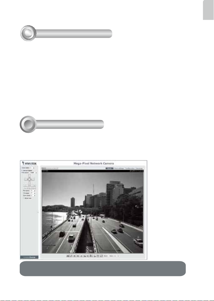
Ready to Use
1. A browser session with the Network Camera should prompt as shown below.
2. You should be able to see live video from your camera. You may also install the
32-channel recording software from the software CD in a deployment consisting of
multiple cameras. For its installation details, please refer to its related documents.
English
For further setup, please refer to the user’s manual on the software CD.
EN - 5
Page 7
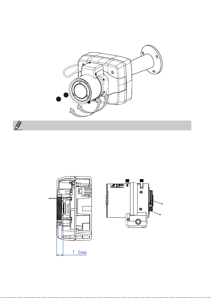
3. Unscrew the zoom controller to adjust the zoom factor. Upon completion, tighten the
zoom controller.
4. Unscrew the focus controller to adjust the focus range. Upon completion, tighten the
focus controller.
T
3
4
W
N
NOTE:
If you prefer other lens for your IP8173H, please notice the specications below.
1. If you select a different lens, the distance between the ange of the lens and the IR
cut lter on the camera should be smaller than 7.0mm. If the lens protrudes too much
from the bottom of the lens module, it may hit the IR Cut Filter, or result in out of focus
when adjusting the focus controller.
2. A vari-focal lens may protrude from the bottom of screw mount when tuning the focus
puller.
∞
IR Cut
Filter
Lens
protrudes from
the screw
mount
Screw mount
3. Use the included hex wrench to make adjustments to CS-mount ring only when you
experience compatibility issue with lens focal length.
EN - 6
Page 8
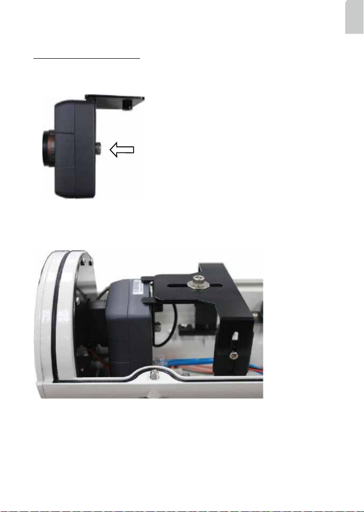
Installed into Housing
1. Attach the bracket to the back of the camera by resting the foam pads on the top and
to the back of the camera. Secure the bracket by driving a hex socket screw.
The camera can be installed into VIVOTEK's
housings, such as the AE-211/-232/-233/-234/-235
series.
2. Attach the T-bracket and the camera to the camera bracket. Place the camera lens in
the front as close as possible to the enclosure's tempered glass window. Secure the
installation by tightening the hex socket screw on top.
English
EN - 7
Page 9
P/N:625021901G Rev. 1.1
All specications are subject to change without notice.
c
Copyright 2013 VIVOTEK INC. All rights reserved.
VIVOTEK INC.
6F, No.192, Lien-Cheng Rd., Chung-Ho, New Taipei City, 235, Taiwan, R.O.C.
VIVOTEK Netherlands B.V.
Busplein 36, 1315KV, Almere, The Netherlands
VIVOTEK USA, INC.
2050 Ringwood Avenue, San Jose, CA 95131
 Loading...