

Vivotek IP7153, IP7154 User Manual

VIVOTEK - A Leading Provider of Multimedia Communication Solutions
2 - User's Manual
Table of Contents
Overview.......................................................................................................................................................3
Read Before Use �������������������������������������������������������������������������������������������������������������������������������������3
Package Contents ����������������������������������������������������������������������������������������������������������������������������������� 3
Physical Description �������������������������������������������������������������������������������������������������������������������������������� 4
Installation ....................................................................................................................................................6
Hardware Installation �������������������������������������������������������������������������������������������������������������������������������6
Network Deployment ������������������������������������������������������������������������������������������������������������������������������� 7
Software Installation ������������������������������������������������������������������������������������������������������������������������������ 11
Ready to Use �����������������������������������������������������������������������������������������������������������������������������������������12
Accessing the Network Camera .................................................................................................................13
Using Web Browsers �����������������������������������������������������������������������������������������������������������������������������13
Using RTSP Players ������������������������������������������������������������������������������������������������������������������������������15
Using 3GPP-compatible Mobile Devices �����������������������������������������������������������������������������������������������16
Using VIVOTEK Recording Software ���������������������������������������������������������������������������������������������������� 17
Main Page ..................................................................................................................................................18
Client Settings ............................................................................................................................................22
Conguration ..............................................................................................................................................24
System ��������������������������������������������������������������������������������������������������������������������������������������������������25
Security �������������������������������������������������������������������������������������������������������������������������������������������������27
HTTPS ���������������������������������������������������������������������������������������������������������������������������������������������������28
Network �������������������������������������������������������������������������������������������������������������������������������������������������33
Wireless LAN (IP7154 only) ������������������������������������������������������������������������������������������������������������������44
DDNS ����������������������������������������������������������������������������������������������������������������������������������������������������47
Access List ��������������������������������������������������������������������������������������������������������������������������������������������49
Audio and Video ������������������������������������������������������������������������������������������������������������������������������������ 52
Motion Detection �����������������������������������������������������������������������������������������������������������������������������������61
Camera Control ������������������������������������������������������������������������������������������������������������������������������������� 64
Camera Tampering Detection ���������������������������������������������������������������������������������������������������������������69
Application ���������������������������������������������������������������������������������������������������������������������������������������������73
Recording ���������������������������������������������������������������������������������������������������������������������������������������������� 86
System Log �������������������������������������������������������������������������������������������������������������������������������������������89
View Parameters ����������������������������������������������������������������������������������������������������������������������������������� 90
Maintenance ������������������������������������������������������������������������������������������������������������������������������������������91
Appendix ....................................................................................................................................................95
URL Commands for the Network Camera ���������������������������������������������������������������������������������������������95
Technical Specications ����������������������������������������������������������������������������������������������������������������������146
Technology License Notice ������������������������������������������������������������������������������������������������������������������147
Electromagnetic Compatibility (EMC) ��������������������������������������������������������������������������������������������������148

VIVOTEK - A Leading Provider of Multimedia Communication Solutions
User's Manual - 3
Overview
VIVOTEK’s IP7153 (PoE) / 7154 (WLAN), equipped with a progressive scan CCD sensor,
delivers superior-quality, crystal-clear video for professional surveillance applications such as
monitoring banks, airports, parking lots, and trafc control, etc.
It can capture razor-sharp, high-resolution images of moving objects that traditional interlacedscan techniques cannot achieve� Furthermore, working in combination with the high-
performance CCD sensor is a removable IR-cut lter that can deliver high-quality images even
under infrared illuminated conditions� With our self-developed VIVOTEK VVTK-1000 SoC, the
camera simultaneously delivers dual streams for real-time monitoring�
The IP7153 / 7154 also comes with many useful functionalities that give users exibilities such
as built-in 802�3af compliant PoE (IP7153), 802�11b/g WLAN connection (IP7154), multi-lingual
user interface, vari-focal CS mount lens, two-way audio via SIP protocol, and digital I/O for
external sensor and alarm. The VIVOTEK IP7153/IP7154 is by far the best choice for a high-
performance, professional surveillance system�
Read Before Use
The use of surveillance devices may be prohibited by law in your country� The Network Camera
is not only a high-performance web-ready camera but can also be part of a exible surveillance
system� It is the user’s responsibility to ensure that the operation of such devices is legal before
installing this unit for its intended use�
It is important to rst verify that all contents received are complete according to the Package
Contents listed below� Take note of the warnings in the Quick Installation Guide before the
Network Camera is installed; then carefully read and follow the instructions in the Installation
chapter to avoid damage due to faulty assembly and installation� This also ensures the product
is used properly as intended�
The Network Camera is a network device and its use should be straightforward for those who
have basic networking knowledge� It is designed for various applications including video sharing,
general security/surveillance, etc. The Conguration chapter suggests ways to best utilize the
Network Camera and ensure proper operations� For creative and professional developers, the
URL Commands of the Network Camera section serves as a helpful reference to customizing
existing homepages or integrating with the current web server.
Package Contents
■ IP7153/7154
■ Power Adapter
■ Camera Stand
■ Lens
■ Software CD
■ Warranty Card
■ Quick Installation Guide
■ Antenna (IP7154 only)
VIVOTEK - A Leading Provider of Multimedia Communication Solutions
4 - User's Manual
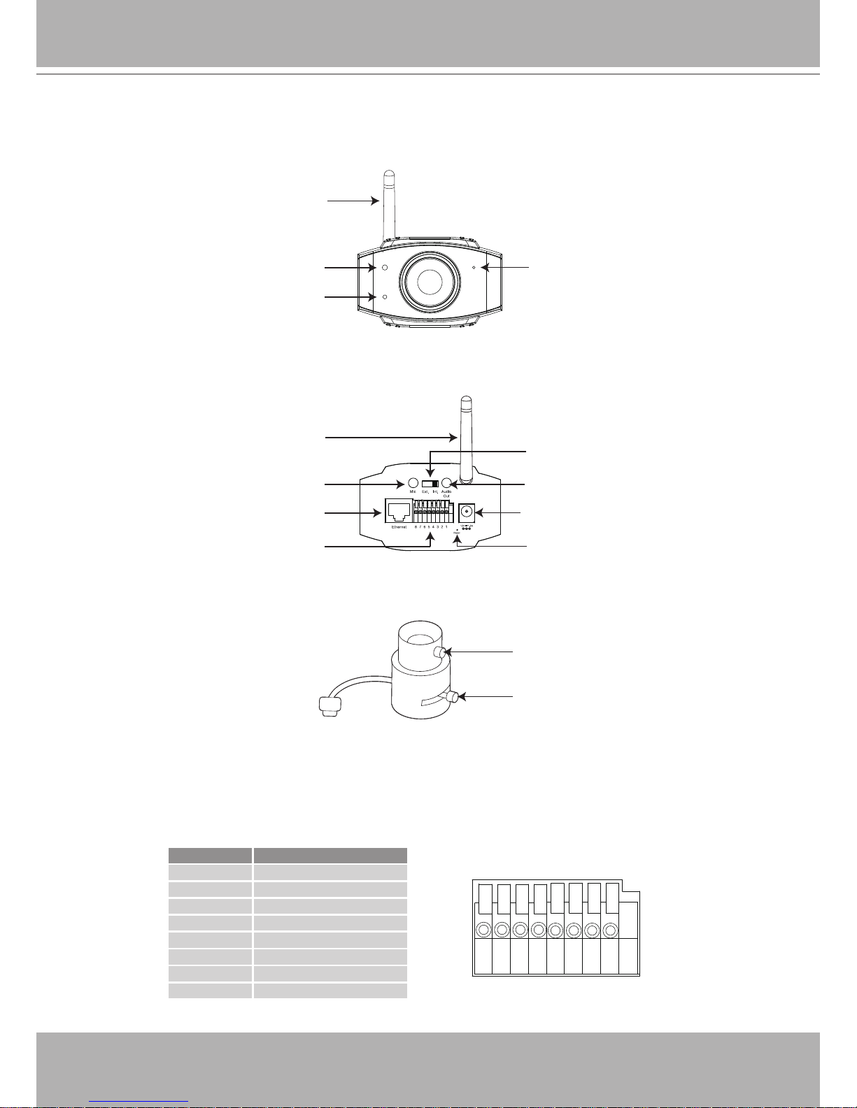
Physical Description
Front Panel
Back Panel
Lens
General I/O Terminal Block
This Network Camera provides a general I/O terminal block which is used to connect external
input / output devices. The pin denitions are described below.
12345678
Pin Name
1 Power +12V
2 Digital Output
3 Digital Input
4 Ground
5 AC 24V input
6 AC 24V input
7 RS-485 8 RS-485 +
Focus Controller
Zoom Controller
Built-in Microphone
Light Sensor
Status LED
Antenna
(IP7154 only)
Power Cord Socket
Ethernet 10/100
RJ45 Socket
Recessed Reset Button
General I/O
Terminal Block
Audio Out
Microphone In
External/Internal
Microphone Switch
Antenna
(IP7154 only)
VIVOTEK - A Leading Provider of Multimedia Communication Solutions
User's Manual - 5
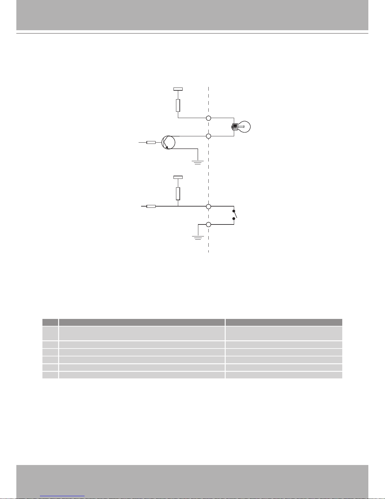
DI/DO Diagram
Refer to the following illustration for the connection method�
12V
+12V
Digital output
PIN 1
Power+12V
PIN 2
Digital input
PIN 3
Ground
PIN 4
Status LED
The LED indicates the status of the Network Camera�
Item LED status Description
1
All LED light => All LED unlight => Steady Red => Steady
Red + Blink Green once per sec�
System booting
2 Steady Red Power on; Network fail
3 All LED unlight Power off
4 Steady Red + Blink Green every 1 sec� Network works (heartbeat)
5 Blink Red every 0�15 sec� + Blink Green every 1 sec� Upgrading firmware
6 Blink Red every 0�15 sec� + Blink Green every 0�15 sec� Restore default
VIVOTEK - A Leading Provider of Multimedia Communication Solutions
6 - User's Manual
Hardware Reset
The reset button is used to reset the system or restore the factory default settings� Sometimes
resetting the system can return the camera to normal operation� If the system problems remain
after reset, restore the factory settings and install again�
Reset: Press and release the indented reset button with a paper clip or thin object� Wait for the
Network Camera to reboot�
Restore: Press and hold the reset button until the status LED rapidly blinks� It takes about 30
seconds� Note that all settings will be restored to factory default� Upon successful restore, the
status LED will blink green and red during normal operation�
Installation
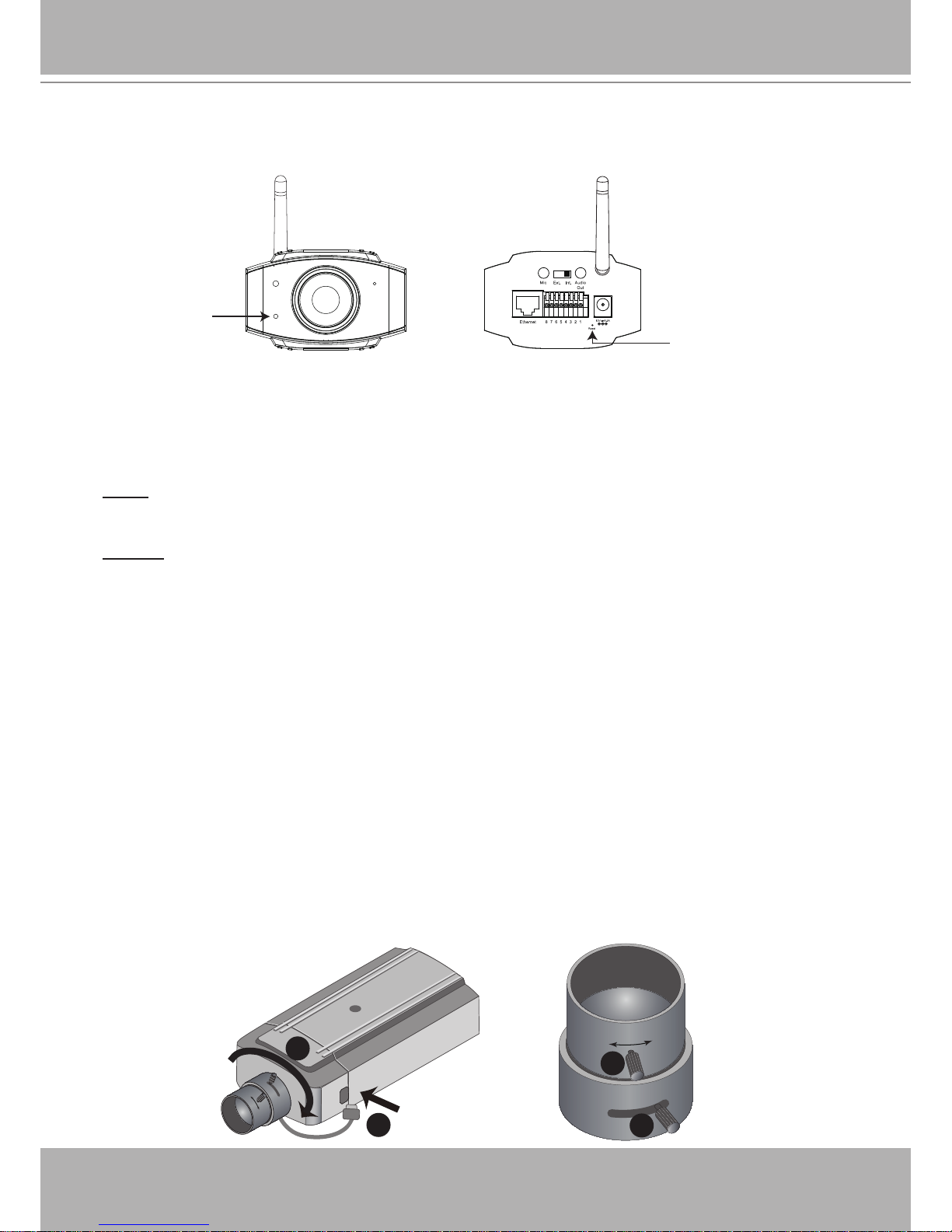
Hardware Installation
Follow the steps below to mount the lens to the Network Camera:
1� Mount the lens by turning it clockwise onto the camera mount until it stops� If necessary, turn
the lens counterclockwise slowly until it gets the best attitude�
2� Connect the lens cable plug to the camera connector�
3� Unscrew the zoom controller to adjust the zoom factor� Upon completion, tighten the zoom
controller�
4� Unscrew the focus controller to adjust the focus range� Upon completion, tighten the focus
controller�
Status LED
Recessed Reset Button
1
2
W
∞
N
T
4
3
VIVOTEK - A Leading Provider of Multimedia Communication Solutions
User's Manual - 7
Network Deployment
Setting up the Network Camera over the Internet
This section explains how to congure the Network Camera to an Internet connection�
1. If you have external devices such as sensors and alarms, make the connection from the
general I/O terminal block�
2� Connect the camera to a switch via Ethernet cable�
3� Connect the supplied power cable from the Network Camera to a power outlet�
There are several ways to set up the Network Camera over the Internet� The rst way is to set
up the Network Camera behind a router� The second way is to utilize a static IP� The third way is
to use PPPoE�
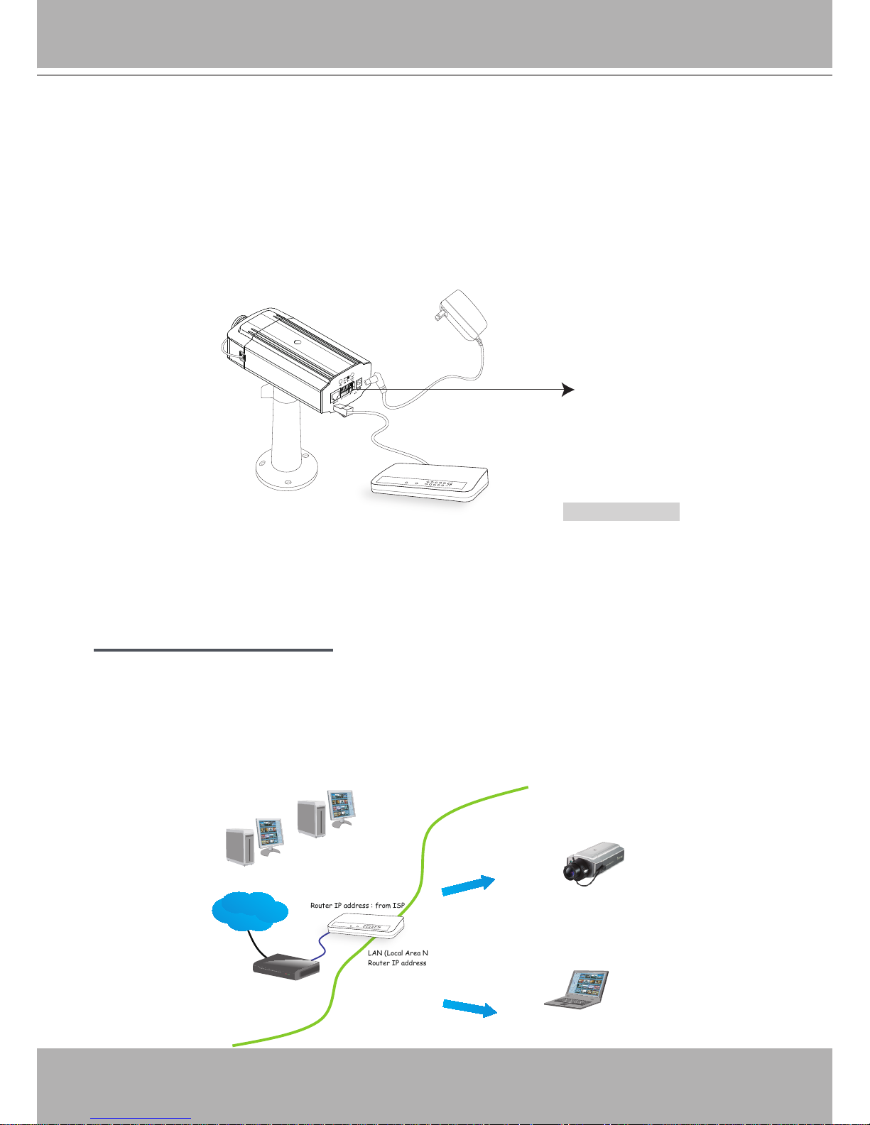
Internet connection via a router
Before setting up the Network Camera over the Internet, make sure you have a router and follow
the steps below�
1� Connect your Network Camera behind a router, the Internet environment is illustrated below�
Regarding how to obtain your IP address, please refer to Software Installation on page 11 for
details�
IP address : 192.168.0.3
Subnet mask : 255.255.255.0
Default router : 192.168.0.1
IP address : 192.168.0.2
Subnet mask : 255.255.255.0
Default router : 192.168.0.1
LAN (Local Area Network)
Router IP address : 192.168.0.1
WAN (Wide Area Network )
Router IP address : from ISP
Cable or DSL Modem
POWER
COLLISION
LINK
RECEIVE
PARTITION
1
2
3
4
5
Internet
POWER
COLLISION
LINK
RECEIV E
PARTITION
1
2
3
4
5
Ethernet Switch
1:Power +12V
2:Digital output
3:Digital input
4:Ground
5:AC 24V
6:AC 24V
7:RS4858:RS485+

VIVOTEK - A Leading Provider of Multimedia Communication Solutions
8 - User's Manual
2� In this case, if the Local Area Network (LAN) IP address of your Network Camera is
192�168�0�3, please forward the following ports for the Network Camera on the router�
■ HTTP port
■ RTSP port
■ RTP port for audio
■ RTCP port for audio
■ RTP port for video
■ RTCP port for video
If you have changed the port numbers on the Network page, please open the ports accordingly
on your router� For information on how to forward ports on the router, please refer to your
router’s user’s manual�
3� Find out the public IP address of your router provided by your ISP (Internet Service Provider)�
Use the public IP and the secondary HTTP port to access the Network Camera from the
Internet� Please refer to Network Type on page 33 for details�
Internet connection with static IP
Choose this connection type if you are required to use a static IP for the Network Camera�
Please refer to LAN on page 33 for details�
Internet connection via PPPoE (Point-to-Point over Ethernet)
Choose this connection type if you are connected to the Internet via a DSL Line� Please refer to
PPPoE on page 34 for details�
VIVOTEK - A Leading Provider of Multimedia Communication Solutions
User's Manual - 9
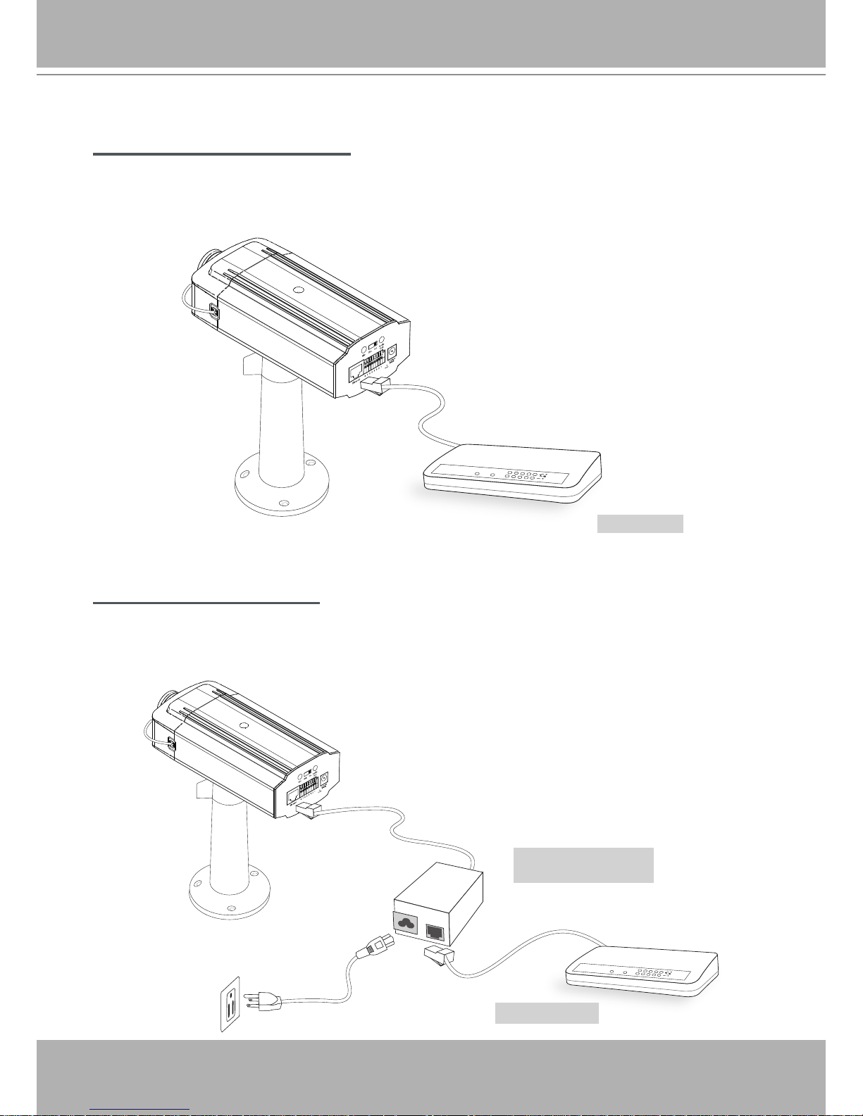
Set up the Network Camera through Power over Ethernet (PoE)
When using a PoE-enabled switch
The Network Camera is PoE-compliant, which allows it to be powered via a single Ethernet
cable� If your switch/router supports PoE, refer to the following illustration to connect the
Network Camera to a PoE-enabled switch/router�
POWER
COLLISION
LINK
RECEIVE
PARTITION
1
2
3
4
5
When using a non-PoE switch
If your switch/router does not support PoE, use a PoE power injector (optional) to connect
between the Network Camera and a non-PoE switch/router�
PoE Switch
POWER
COLLISION
LINK
RECEIVE
PARTITION
1
2
3
4
5
Non-PoE Switch
PoE Power Injector
(optional)
power + data transmission
VIVOTEK - A Leading Provider of Multimedia Communication Solutions
10 - User's Manual
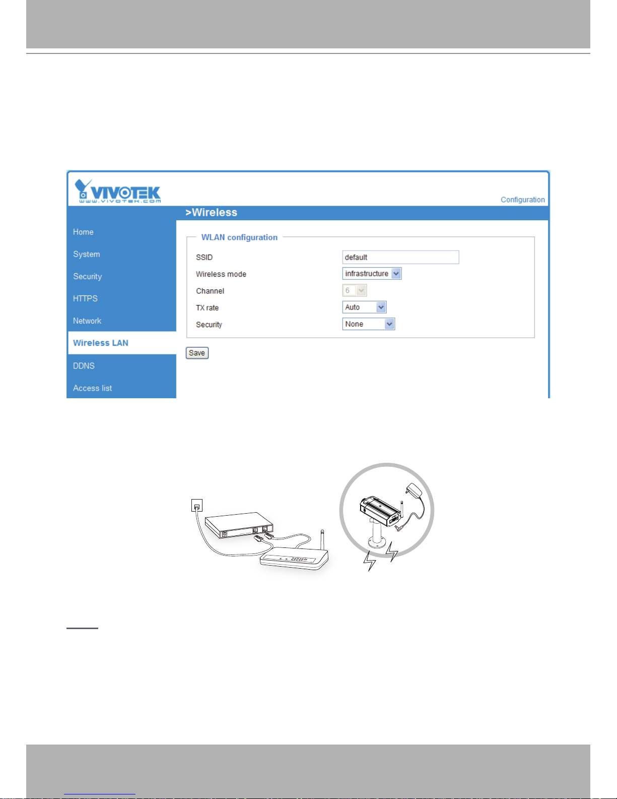
Set up the Network Camera through Wireless Connection (IP7154 only)
1� Check the SSID for your wireless access point (AP)�
2. Go to the IP7154 Conguration page > Advanced mode > Wireless LAN.
3� Type in the SSID the same as your AP�
4� Select the Wireless mode as “Infrastructure”�
5� Click Save� The Network Camera will reboot�
6� Wait for the live image to be reloaded to your browser� Then, unplug the power cable and
Ethernet cable from the Network Camera�
7� Replug the power cable to the camera� The Network Camera will now operate in wireless
mode�
NOTE
► SSID, abbreviated from Service Set Identier, is the name assigned to the wireless network.
The IP7154 factory SSID setting is set to “default”�
► Select “Ad-Hoc” wireless mode if you want the IP7154 to communicate without using an AP
or wireless router�
► For detailed information about wireless connection, please refer to Wireless LAN on page 44�
POWER
COLLISION
LINK
RECEIVE
PARTITION
1
2
3
4
5
ADSL/Cable/Hub
AP
VIVOTEK - A Leading Provider of Multimedia Communication Solutions
User's Manual - 11
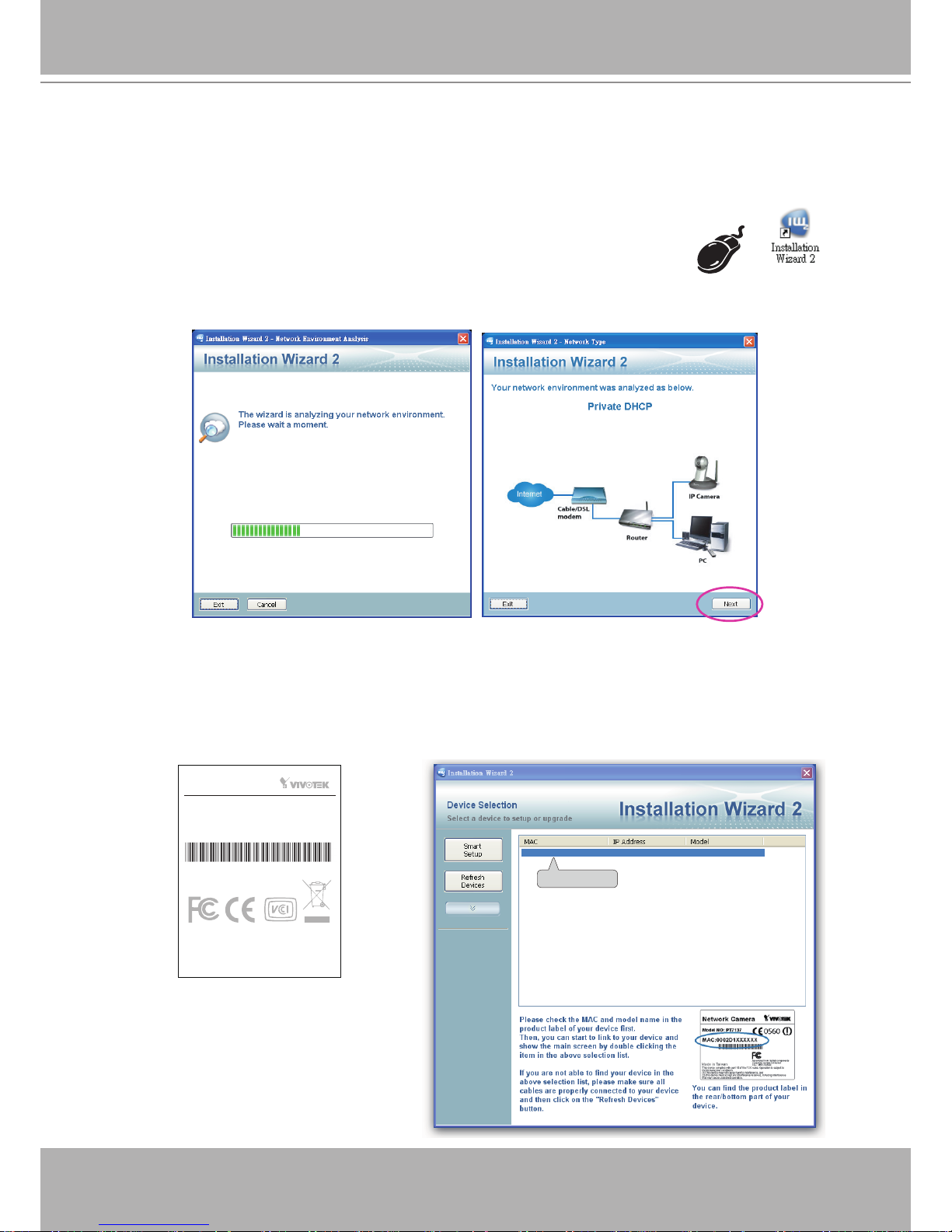
Software Installation
Installation Wizard 2 (IW2), free-bundled software included on the product CD, helps you set up
your Network Camera on the LAN�
1� Install IW2 under the Software Utility directory from the software CD�
Double click the IW2 shortcut on your desktop to launch the program�
2� The program will conduct an analysis of your network environment�
After your network environment is analyzed, please click Next to continue the program�
3� The program will search for all VIVOTEK network devices on the same LAN�
4� After searching, the main installer window will pop up� Click on the MAC and model name
which matches the product label on your device to connect to the Network Camera via
Internet Explorer.
0002D1070417
00-02-D1-07-04-17 192.168.5.151 IP7153
This device complies with part 15 of the FCC rules. Operation is subject to
the following two conditions:
(1)This device may not cause harmful interference, and
(2) this device must accept any interference received, including interference
that may cause undesired operation.
RoHS
Network Camera
Model No:IP7153
Pat. 6,930,709 Made in Taiwan
MAC:0002D1070417
VIVOTEK - A Leading Provider of Multimedia Communication Solutions
12 - User's Manual
Ready to Use
1� Access the Network Camera from the LAN�
2� Retrieve live video through a web browser or recording software�
VIVOTEK - A Leading Provider of Multimedia Communication Solutions
User's Manual - 13
Accessing the Network Camera
This chapter explains how to access the Network Camera through web browsers, RTSP players,
3GPP-compatible mobile devices, and VIVOTEK recording software�
Using Web Browsers
Use Installation Wizard 2 (IW2) to access to the Network Cameras on the LAN�
If your network environment is not a LAN, follow these steps to access the Netwotk Camera:
1. Launch your web browser (ex. Microsoft
®
Internet Explorer, Mozilla Firefox, or Netscape).
2. Enter the IP address of the Network Camera in the address eld. Press Enter�
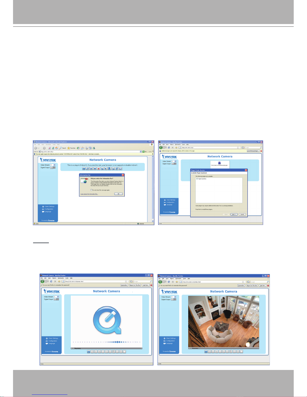
3� The live video will be displayed in your web browser�
4. If it is the rst time installing the VIVOTEK network camera, an information bar will pop up as
shown below� Follow the instructions to install the required plug-in on your computer�
NOTE
► For Mozilla Firefox or Netscape users, your browser will use Quick Time to stream the live
video. If you do not have Quick Time on your computer, please download it rst, then launch
the web browser�
VIVOTEK - A Leading Provider of Multimedia Communication Solutions
14 - User's Manual
► By default, the Network Camera is not password-protected. To prevent unauthorized access,
it is highly recommended to set a password for the Network Camera�
For more information about how to enable password protection, please refer to Security on
page 27�
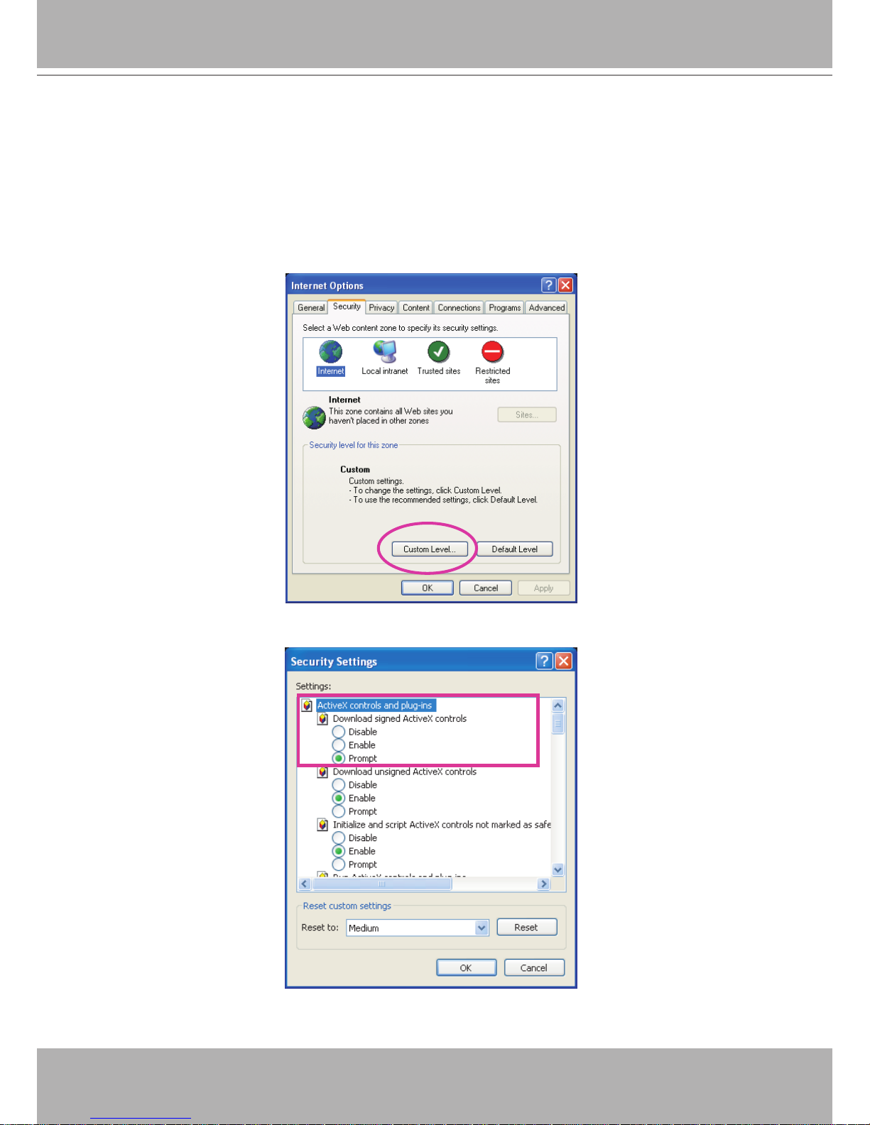
► If you see a dialog box indicating that your security settings prohibit running ActiveX
®
Controls, please enable the ActiveX
®
Controls for your browser�
1� Choose Tools > Internet Options > Security > Custom Level�
2. Look for Download signed ActiveX
®
controls; select Enable or Prompt� Click OK�
3. Refresh your web browser, then install the Active X
®
control� Follow the instructions to
complete installation�
VIVOTEK - A Leading Provider of Multimedia Communication Solutions
User's Manual - 15
Using RTSP Players
To view the MPEG-4 streaming media using RTSP players, you can use one of the following
players that support RTSP streaming�
Quick Time Player
Real Player
VLC media player
mpegable Player
pvPlayer
As most ISPs and players only allow RTSP streaming through port number 554, please set the
RTSP port to 554� For more information, please refer to RTSP Streaming on page 42�
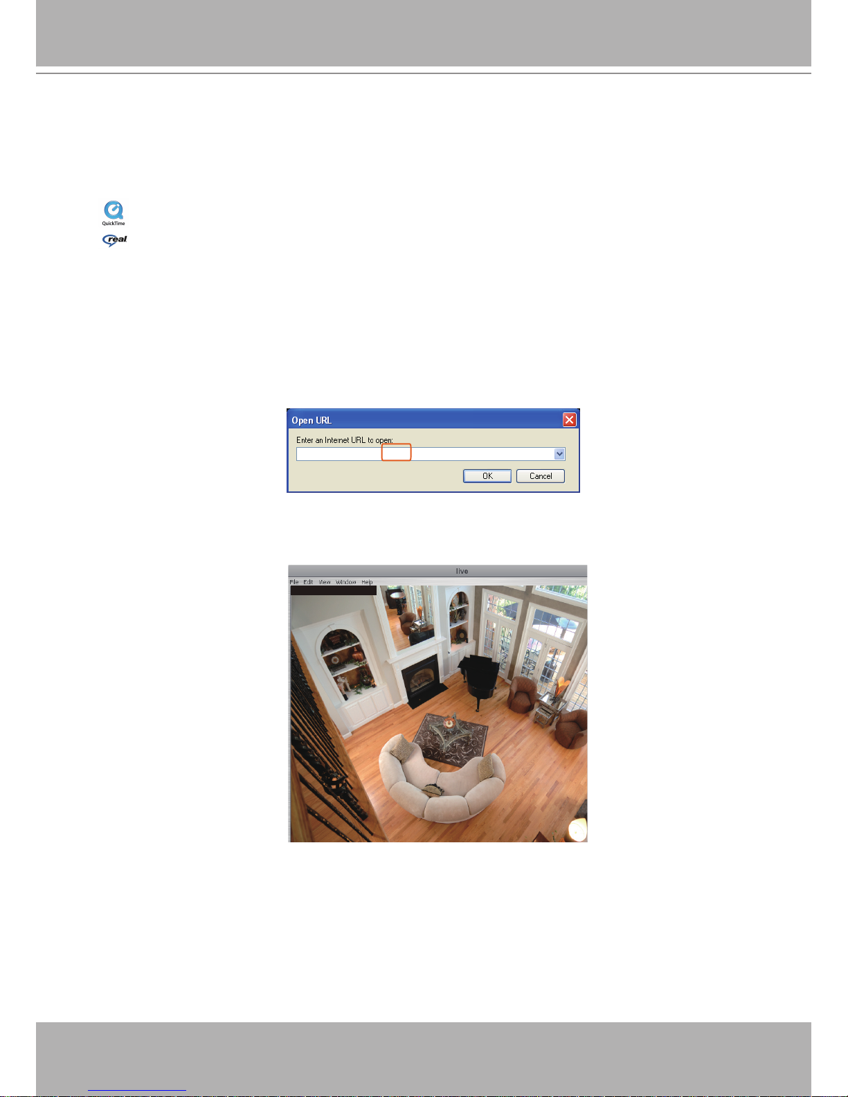
For example:
4� The live video will be displayed in your player�
For more information on how to configure the RTSP access name, please refer to RTSP
Streaming on page 42 for details�
rtsp://192.168.5.151:554/live.sdp
Video 16:38:01 2008/01/03
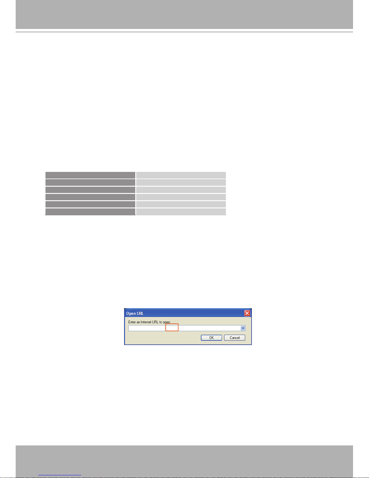
1� Launch the RTSP player�
2. Choose File > Open URL. A URL dialog box will pop up.
3� The address format is rtsp://<ip address>:<rtsp port>/<RTSP streaming access name for
stream1 or stream2>
VIVOTEK - A Leading Provider of Multimedia Communication Solutions
16 - User's Manual
Using 3GPP-compatible Mobile Devices
To view the streaming media through 3GPP-compatible mobile devices, make sure the Network
Camera can be accessed over the Internet� For more information on how to set up the Network
Camera over the Internet, please refer to Setup the Network Camera over the Internet on page 7�
To utilize this feature, please check the following settings on your Network Camera:
1� Because most players on 3GPP mobile phones do not support RTSP authentication, make
sure the authentication mode of RTSP streaming is set to disable�
For more information, please refer to RTSP Streaming on page 42�
2� As the the bandwidth on 3G networks is limited, you will not be able to use a large video size�
Please set the video and audio streaming parameters as listed below�
For more information, please refer to Audio and Video on page 52�
Video Mode MPEG-4
Frame size 176 x 144
Maximum frame rate 5 fps
Intra frame period 1S
Video quality (Constant bit rate) 40kbps
Audio type (GSM-AMR) 12.2kbps
3� As most ISPs and players only allow RTSP streaming through port number 554, please set
the RTSP port to 554� For more information, please refer to RTSP Streaming on page 42�
4. Launch the player on the 3GPP-compatible mobile devices (ex. Real Player).
5� Type the following URL commands in the player�
The address format is rtsp://<public ip address of your camera>:<rtsp port>/<RTSP streaming
access name for stream1 or stream2>�
For example:
rtsp://192.168.5.151:554/live.sdp

VIVOTEK - A Leading Provider of Multimedia Communication Solutions
User's Manual - 17
Using VIVOTEK Recording Software
The product software CD also contains recording software, allowing simultaneous monitoring
and video recording for multiple Network Cameras� Please install the recording software; then
launch the program to add the Network Camera to the Channel list� For detailed information
about how to use the recording software, please refer to the user’s manual of the software or
download it from http://www�vivotek�com�
VIVOTEK - A Leading Provider of Multimedia Communication Solutions
18 - User's Manual
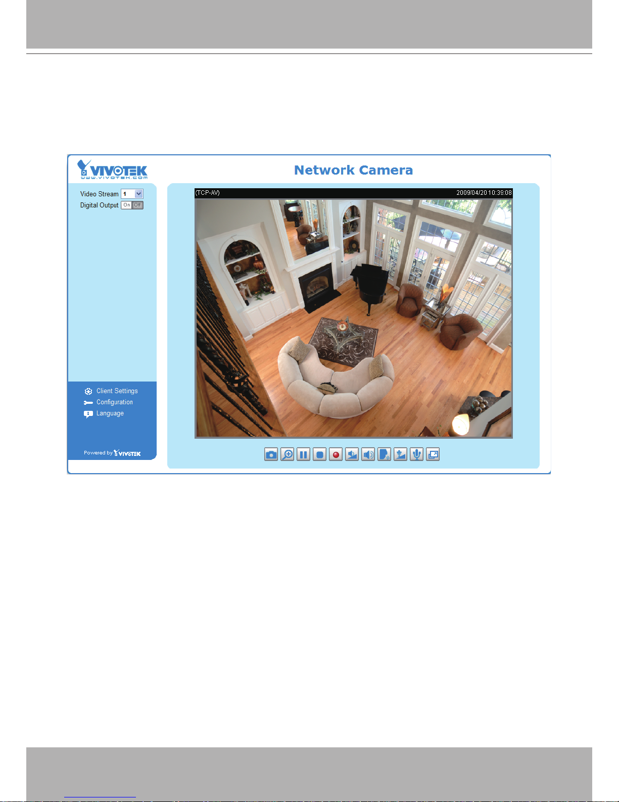
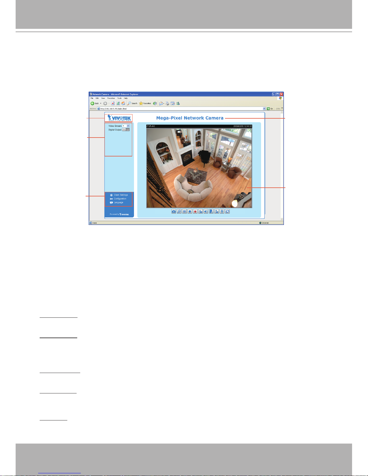
Main Page
This chapter explains the layout of the main page. It is composed of the following sections:
VIVOTEK INC� Logo, Host Name, Camera Control Area, Configuration Area, and Live Video
Window�
VIVOTEK INC. Logo
Click this logo to visit the VIVOTEK website�
Host Name
The host name can be customized to t your needs. For more information,
please refer to
System on page
25�
Camera Control Area
Video Stream: This Network Cmera supports MJPEG or MPEG-4 dual streams simultaneously� You can
select either one for live viewing�
Digital Output: Click to turn the digital output device on or off�
Conguration Area
Client Settings: Click this button to access the client setting page� For more information, please refer to
Client Settings on page 22�
Conguration: Click this button to access the conguration page of the Network Camera. It is suggested
that a password be applied to the Network Camera so that only the administrator can configure the
Network Camera� For more information, please refer to Conguration on page 24�
Language: Click this button to choose a language for the user interface� Language options are available
in: English, Deutsch, Español, Français, Italiano,
日本語
, Português,
簡体中文
, and
繁體中文
�
VIVOTEK INC. Logo
Live View Window
Camera Control Area
Configuration Area
Host Name
VIVOTEK - A Leading Provider of Multimedia Communication Solutions
User's Manual - 19
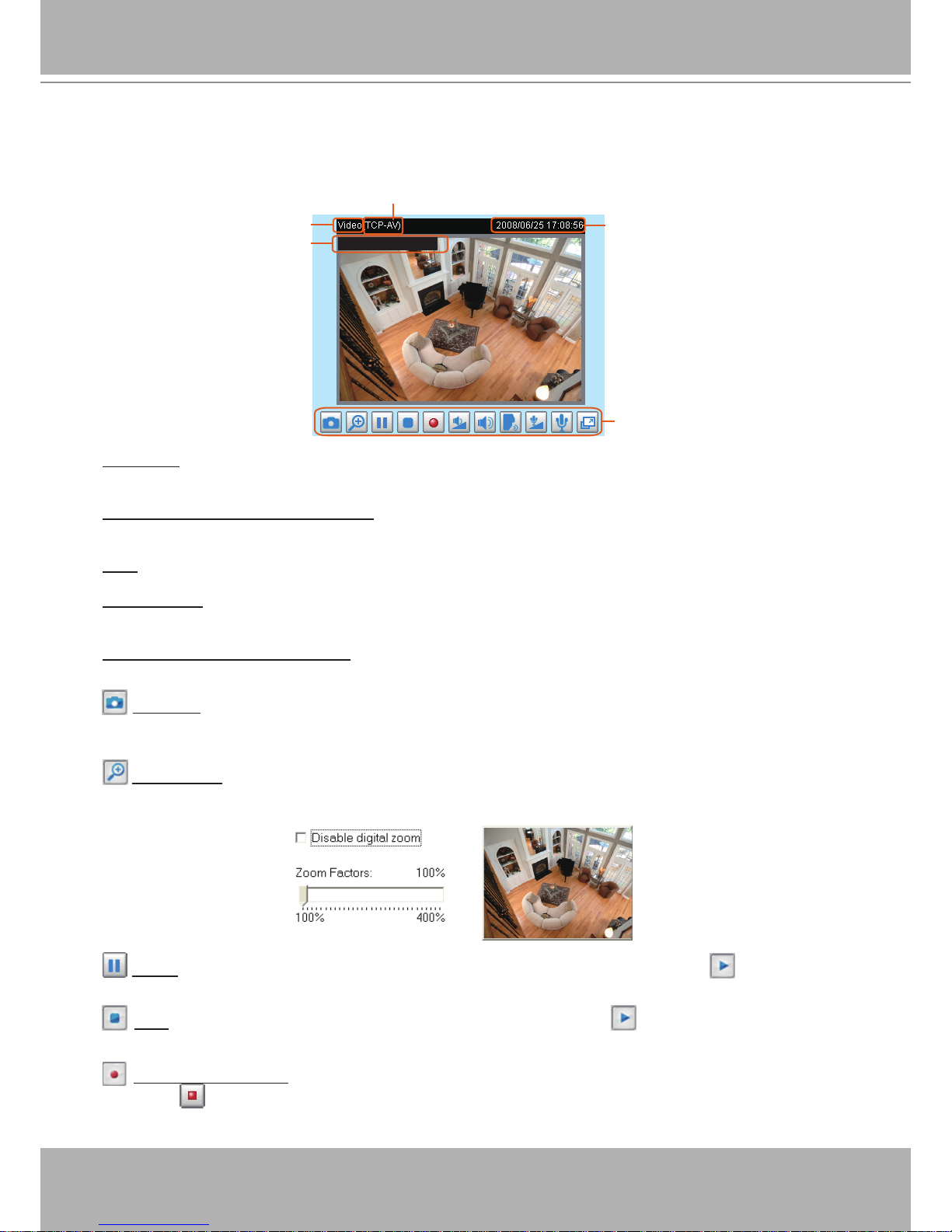
Live Video Window
■ The following window is displayed when the video mode is set to MPEG-4:
Video Title: The video title can be congured. For more information, please refer to Video Settings on
page 52�
MPEG-4 Protocol and Media Options: The transmission protocol and media options for MPEG-4 video
streaming. For further conguration, please refer to Client Settings on page 22�
Time: Display the current time. For further conguration, please refer to Video Settings on page 52�
Title and Time: The video title and time can be stamped on the streaming video. For further conguration,
please refer to Video Settings on page 52�
Video and Audio Control Buttons: Depending on the Network Camera model and Network Camera
conguration, some buttons may not be available.
Snapshot: Click this button to capture and save still images� The captured images will be displayed
in a pop-up window� Right-click the image and choose Save Picture As to save it in JPEG (*�jpg) or BMP
(*�bmp) format�
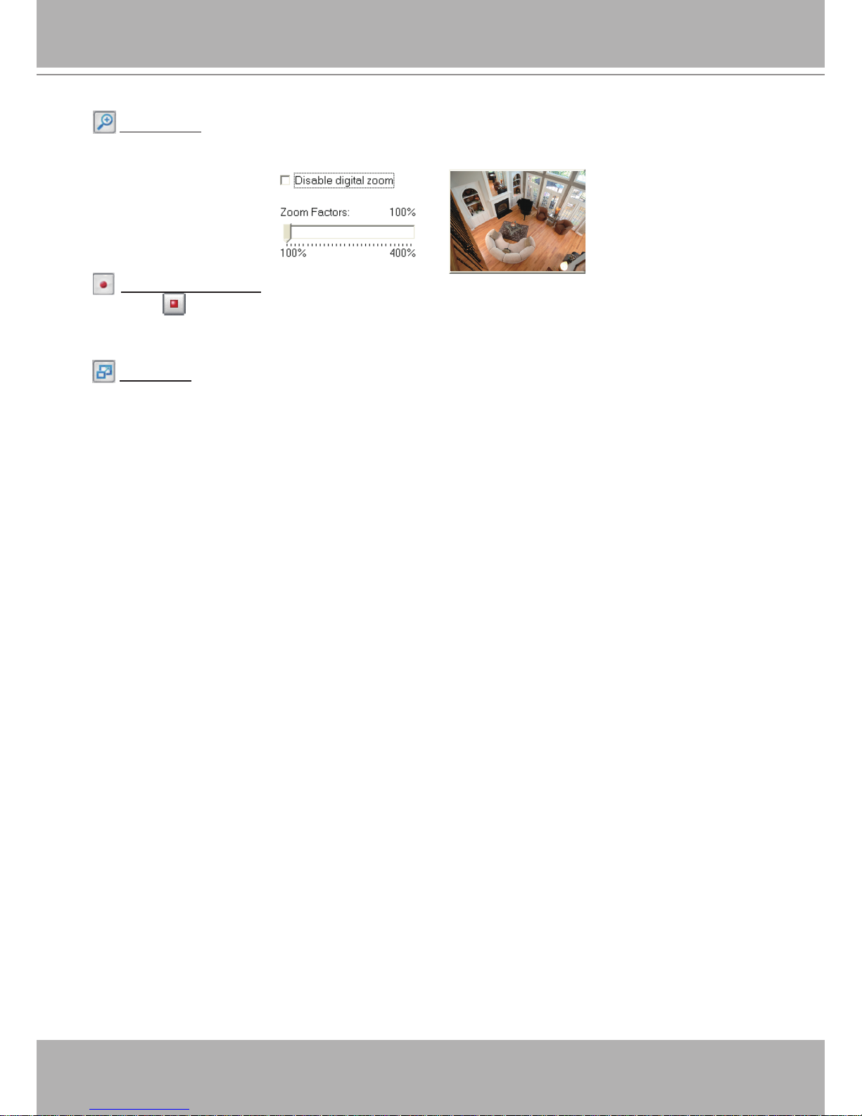
Digital Zoom: Click and uncheck “Disable digital zoom” to enable the zoom operation� The navigation
screen indicates the part of the image being magnied. To control the zoom level, drag the slider bar. To
move to a different area you want to magnify, drag the navigation screen�
Pause: Pause the transmission of the streaming media� The button becomes the Resume button
after clicking the Pause button�
Stop: Stop the transmission of the streaming media� Click the Resume button to continue
transmission�
Start MP4 Recording: Click this button to record video clips in MP4 file format to your computer�
Press the
Stop MP4 Recording button to end recording. When you exit the web browser, video
recording stops accordingly. To specify the storage destination and le name, please refer to MP4 Saving
Options on page 23 for details�
Video and Audio Control Buttons
MPEG-4 Protocol and Media Options
Video Title
Time
Title and Time
Video 17:08:56 2008/06/25
VIVOTEK - A Leading Provider of Multimedia Communication Solutions
20 - User's Manual
Volume: When the Mute function is not activated, move the slider bar to adjust the volume on the
local computer�
Mute: Turn off the volume on the local computer� The button becomes the Audio On button after
clicking the Mute button�
Talk: Click this button to talk to people around the Network Camera� Audio will project from
the external speaker connected to the Network Camera. Click this button
again to end talking
transmission�
Mic Volume: When the Mute function is not activated, move the slider bar to adjust the
microphone volume on the local computer�
Mute: Turn off the Mic volume on the local computer� The button becomes the Mic On button
after clicking the Mute button�
Full Screen: Click this button to switch to full screen mode� Press the “Esc” key to switch back to normal
mode�
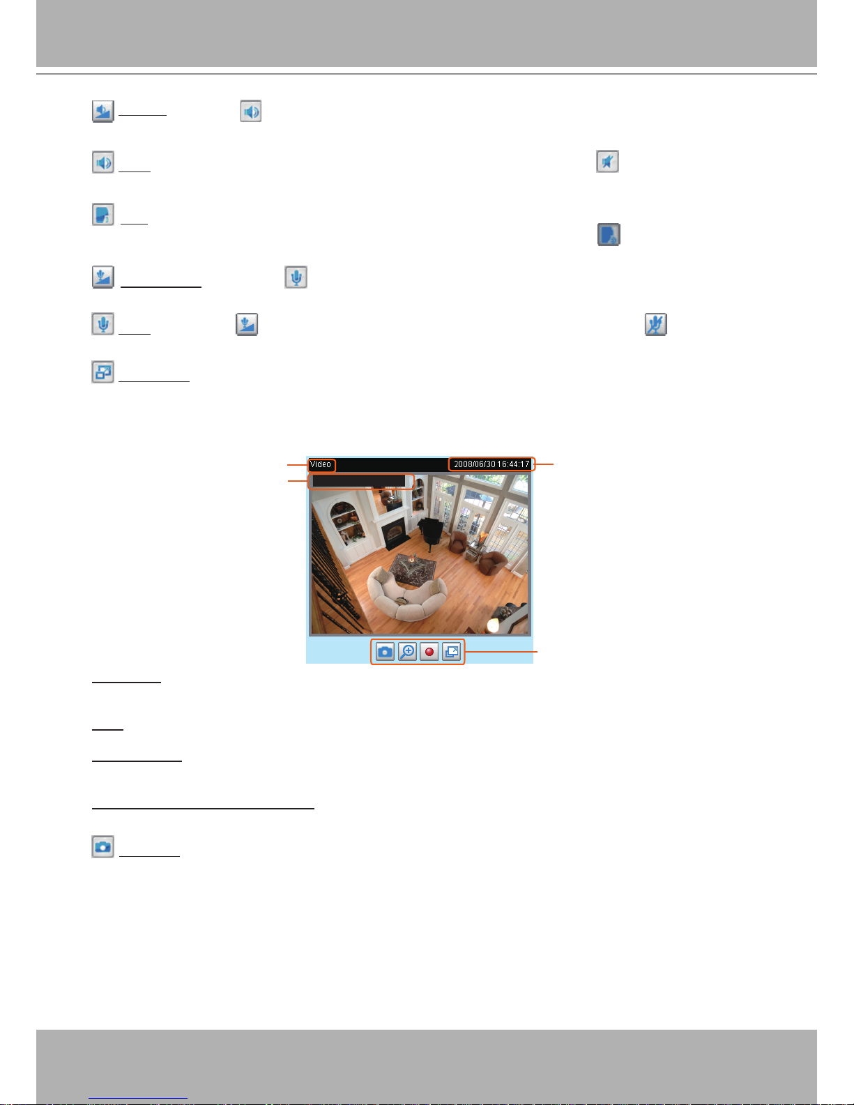
■ The following window is displayed when the video mode is set to MJPEG:
Video Title: The video title can be congured. For more information, please refer to Video Settings on
page 52�
Time: Display the current time� For more information, please refer to
Video Settings on page 52�
Title and Time: Video title and time can be stamped on the streaming video� For more information, please
refer to
Video Settings on page 52�
Video and Audio Control Buttons: Depending on the Network Camera model and Network Camera
conguration, some buttons may not be available.
Snapshot: Click this button to capture and save still images� The captured images will be displayed
in a pop-up window� Right-click the image and choose Save Picture As to save it in JPEG (*�jpg) or BMP
(*�bmp) format�
Time
Video Title
Title and Time
Video Control Buttons
Video 13:44:17 2008/06/30
VIVOTEK - A Leading Provider of Multimedia Communication Solutions
User's Manual - 21
Digital Zoom: Click and uncheck “Disable digital zoom” to enable the zoom operation� The navigation
screen indicates the part of the image being magnied. To control the zoom level, drag the slider bar. To
move to a different area you want to magnify, drag the navigation screen�
Start MP4 Recording: Click this button to record video clips in MP4 file format to your computer�
Press the
Stop MP4 Recording button to end recording. When you exit the web browser, video
recording stops accordingly. To specify the storage destination and le name, please refer to MP4 Saving
Options on page 23 for details�
Full Screen: Click this button to switch to full screen mode� Press the “Esc” key to switch back to normal
mode�
VIVOTEK - A Leading Provider of Multimedia Communication Solutions
22 - User's Manual
Client Settings
This chapter explains how to select the stream transmission mode and saving options on the
local computer� When completed with the settings on this page, click Save on the page bottom
to enable the settings�
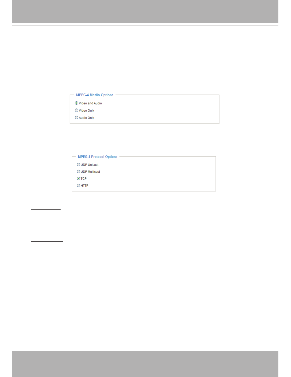
MPEG-4 Media Options
Select to stream video or audio data or both� This is enabled only when the video mode is set to MPEG-4�
MPEG-4 Protocol Options
Depending on your network environment, there are four transmission modes of MPEG-4 streaming:
UDP unicast: This protocol allows for more real-time audio and video streams� However, network
packets may be lost due to network burst trafc and images may be broken. Activate UDP connection
when occasions require time-sensitive responses and the video quality is less important� Note that each
unicast client connecting to the server takes up additional bandwidth and the Network Camera allows up
to ten simultaneous accesses�
UDP multicast: This protocol allows multicast-enabled routers to forward network packets to all clients
requesting streaming media� This helps to reduce the network transmission load of the Network Camera
while serving multiple clients at the same time� Note that to utilize this feature, the Network Camera must
be configured to enable multicast streaming at the same time� For more information, please refer to
RTSP Streaming on page 42�
TCP: This protocol guarantees the complete delivery of streaming data and thus provides better video
quality� The downside of this protocol is that its real-time effect is not as good as that of the UDP protocol�
HTTP: This protocol allows the same quality as TCP protocol without needing to open specic ports for
streaming under some network environments� Users inside a firewall can utilize this protocol to allow
streaming data through�
VIVOTEK - A Leading Provider of Multimedia Communication Solutions
User's Manual - 23
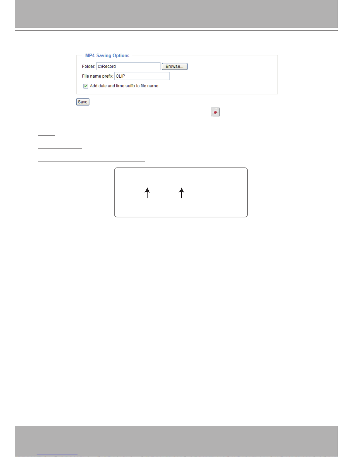
MP4 Saving Options
Users can record live video as they are watching it by clicking Start MP4 Recording on the main
page. Here, you can specify the storage destination and le name.
Folder: Specify a storage destination for the recorded video les.
File Name Prex: Enter the text that will be appended to the front of the video le name.
Add date and time sufx to the le name: Select this option to append the date and time to the end of the
le name.
CLIP_20090108-180853
Date and time suffix
The format is: YYYYMMDD_HHMMSS
File name prefix
VIVOTEK - A Leading Provider of Multimedia Communication Solutions
24 - User's Manual
Conguration
Click Configuration on the main page to enter the camera setting pages� Note that only
Administrators can access the conguration page.
VIVOTEK offers an easy-to-use user interface that helps you set up your network camera with
minimal effort� To simplify the setting procedure, two types of user interfaces are available:
Advanced Mode for professional users and Basic Mode for entry-level users� Some advanced
functions (HTTPS/ Access list/ Homepage layout/ Application/ Recording/ System log/ View
parameters) are not displayed in Basic Mode�
If you want to set up advanced functions, please click [Advanced Mode] on the bottom of the
conguration list to quickly switch to Advanced Mode.
In order to simplify the user interface, the detailed information will be hidden unless you click on
the function item. When you click on the rst sub-item, the detailed information for the rst sub-
item will be displayed; when you click on the second sub-item, the detailed information for the
second sub-item will be displayed and that of the rst sub-item will be hidden.
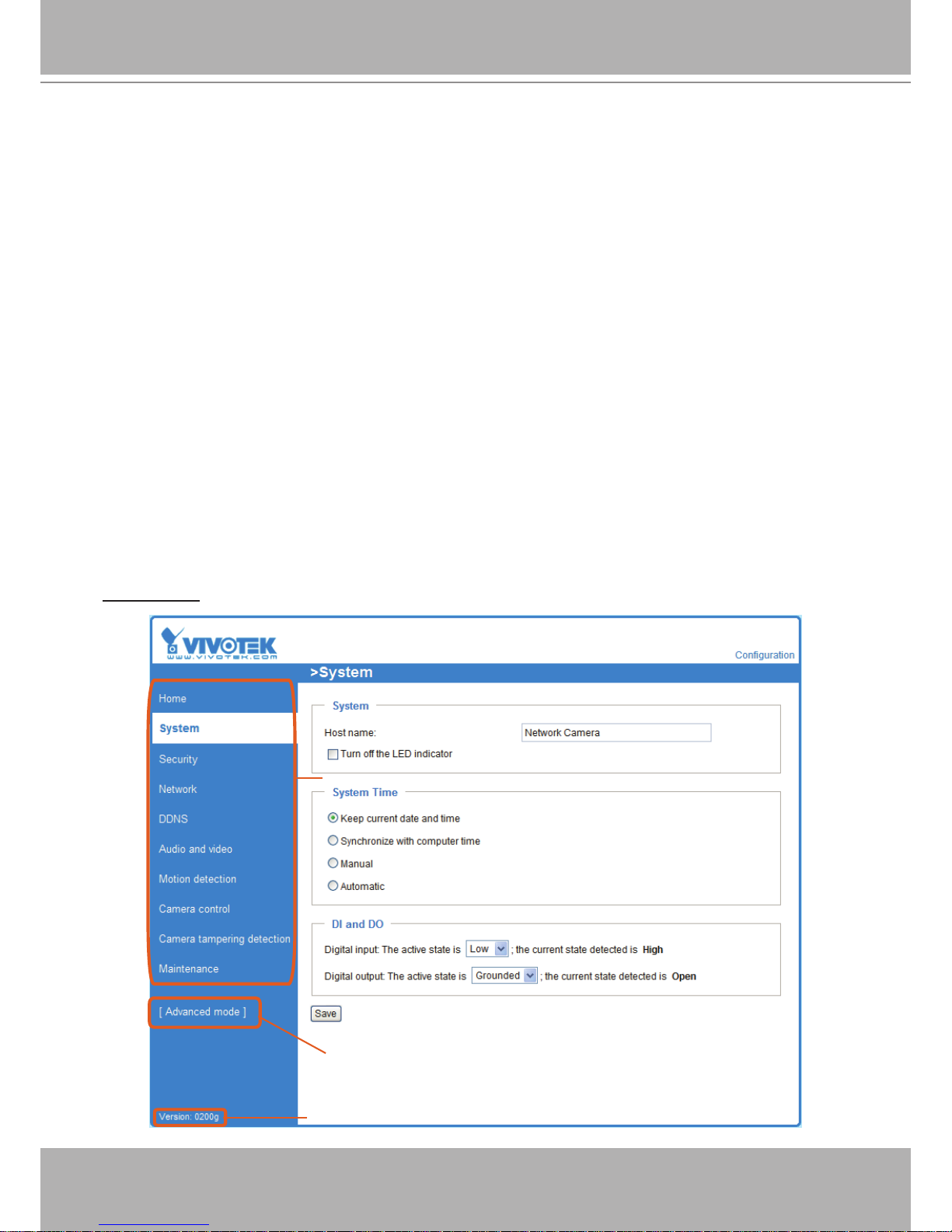
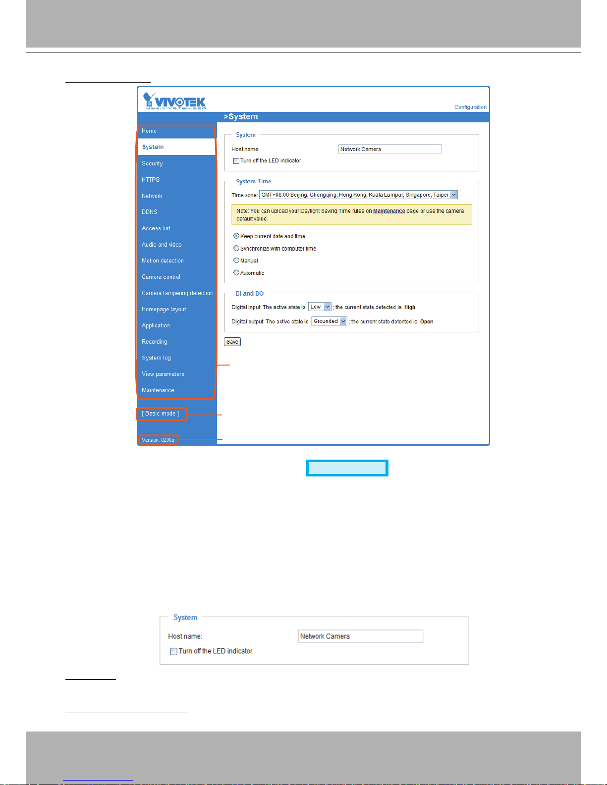
The following is the interface of the Basic Mode and the Advanced Mode:
Basic Mode
Click to switch to Advanced Mode
Firmware Version
Configuration List
VIVOTEK - A Leading Provider of Multimedia Communication Solutions
User's Manual - 25
Advanced Mode
Each function on the conguration list will be explained in the following sections. Those functions that are
displayed only in Advanced Mode are marked with
Advanced Mode
� If you want to set up advanced
functions, please click [Advanced Mode] on the bottom of the conguration list to quickly switch over.
System
This section explains how to congure the basic settings for the Network Camera, such as the
host name and system time� It is composed of the following three columns: System, System
Time and DI and DO� When completed with the settings on this page, click Save at the bottom
of the page to enable the settings�
System
Host name: Enter a desired name for the Network Camera. The text will be displayed at the top of the
main page�
Turn off the LED indicators: If you don’t want to let others know that the network camera is working, you
can select this option to turn off the LED indicators�
Configuration List
Firmware Version
Click to switch to Basic Mode
VIVOTEK - A Leading Provider of Multimedia Communication Solutions
26 - User's Manual
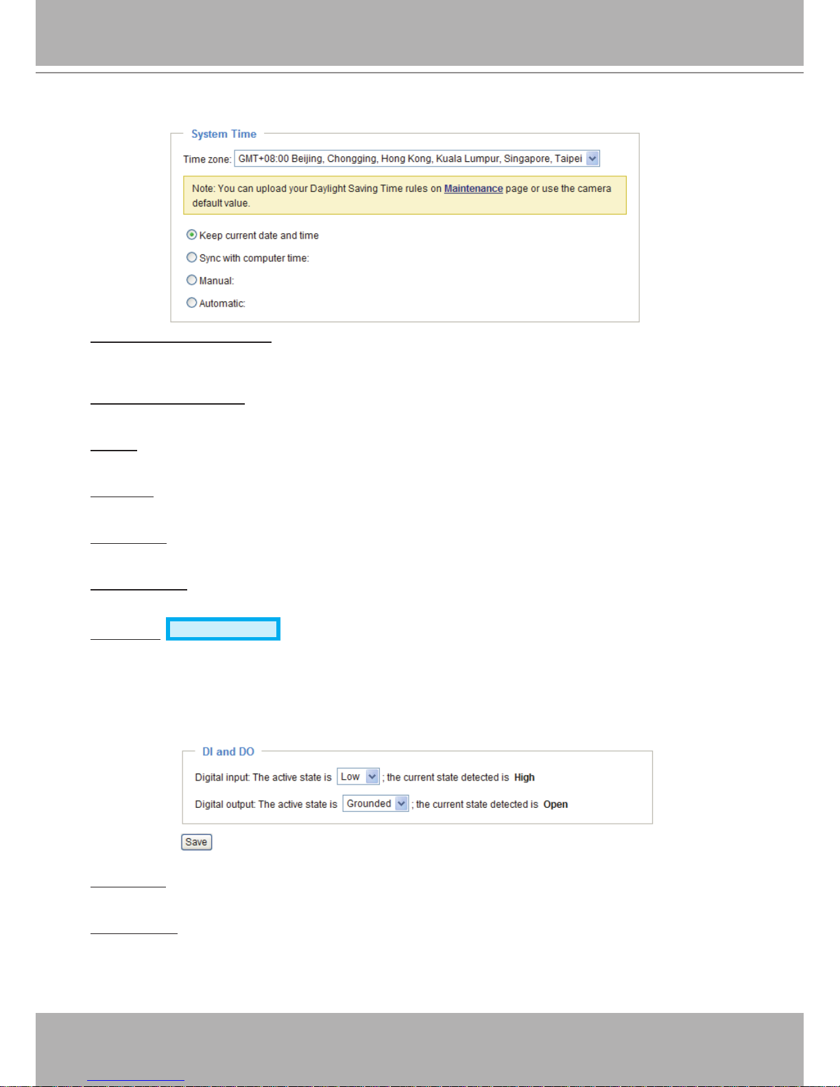
System Time
Keep current date and time: Select this option to preserve the current date and time of the Network
Camera� The Network Camera’s internal real-time clock maintains the date and time even when the
power of the system is turned off�
Sync with computer time: Select this option to synchronize the date and time of the Network Camera with
the local computer� The read-only date and time of the PC is displayed as updated�
Manual: The administrator can enter the date and time manually� Note that the date and time format are
[yyyy/mm/dd] and [hh:mm:ss]�
Automatic: The Network Time Protocol is a protocol which synchronizes computer clocks by periodically
querying an NTP Server�
NTP server: Assign the IP address or domain name of the time-server. Leaving the text box blank
connects the Network Camera to the default time servers�
Update interval: Select to update the time using the NTP server on an hourly, daily, weekly, or monthly
basis�
Time zone
Advanced Mode
: Select the appropriate time zone from the list� If you want to upload
Daylight Savings Time rules on the Maintenance page, please refer to Upload / Export Daylight Saving
Time Conguration File on page 92 for details�
DI and DO
Digital input: Select High or Low to dene normal status for the digital input. The Network Camera will
report the current status�
Digital output: Select Grounded or Open to define normal status for the digital output� The Network
Camera will show whether the trigger is activated or not�
VIVOTEK - A Leading Provider of Multimedia Communication Solutions
User's Manual - 27
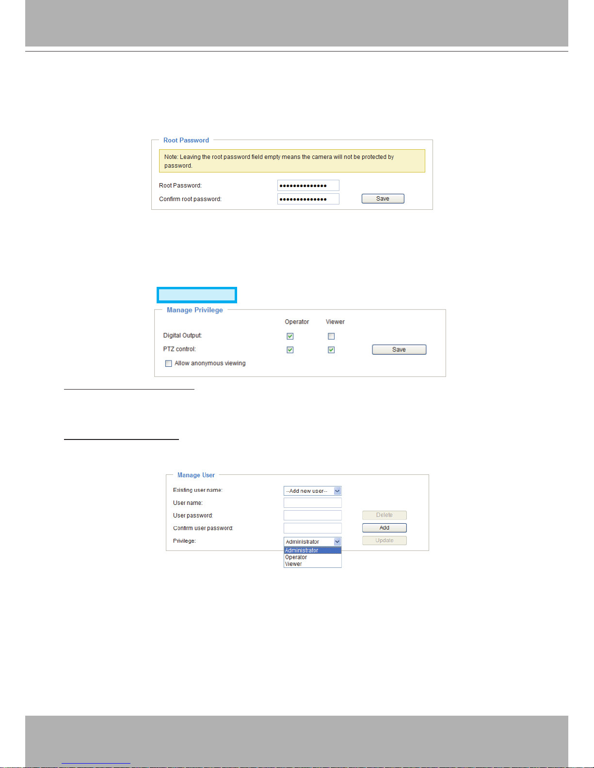
Security
This section explains how to enable password protection and create multiple accounts.
Root Password
The administrator account name is “root”, which is permanent and can not be deleted� If you want to add
more accounts in the Manage User column, please apply the password for the “root” account rst.
1. Type the password identically in both text boxes, then click Save to enable password protection�
2� A window will be prompted for authentication; type the correct user’s name and password in their
respective elds to access the Network Camera.
Manage Privilege
Advanced Mode
Digital Output & PTZ control: You can modify the manage privilege of operators or viewers� Check or
uncheck the item, then click Save to enable the settings� If you give Viewers the privilege, Operators will
also have the ability to control the Network Camera through the main page� (Please refer to Main Page
on page 18�)
Allow anonymous viewing: If you check this item, any client can access the live stream without entering a
User ID and Password�
Manage User
Administrators can add up to 20 user accounts�
1� Input the new user’s name and password�
2� Select the privilege level for the new user account� Click Add to enable the setting�
Access rights are sorted by user privilege (Administrator, Operator, and Viewer)� Only administrators can
access the Conguration page. Though operators cannot access the Congurationpage, they can use
the URL Commands to get and set the value of parameters� For more information, please refer to URL
Commands of the Network Camera on page 95� Viewers access only the main page for live viewing�
Here you also can change a user’s access rights or delete user accounts�
1. Select an existing account to modify.
2� Make necessary changes and click Update or Delete to enable the setting�
VIVOTEK - A Leading Provider of Multimedia Communication Solutions
28 - User's Manual
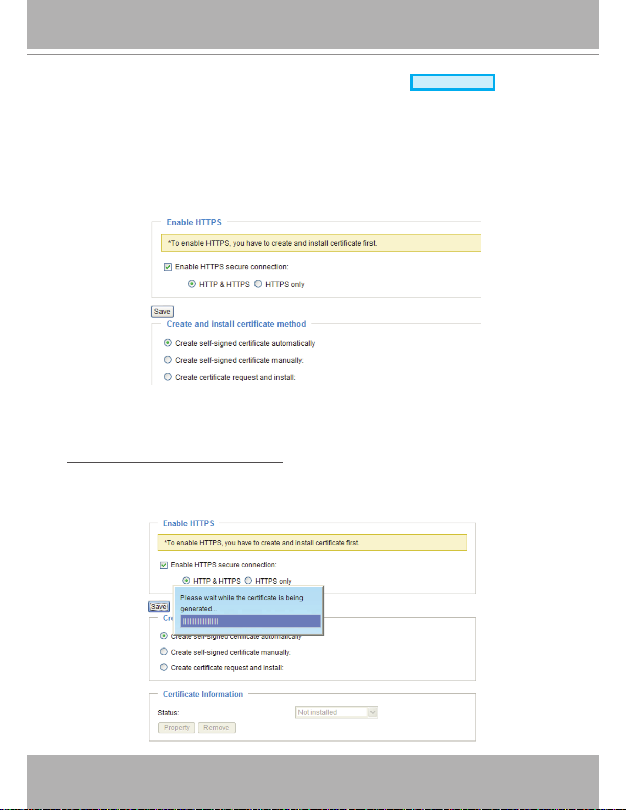
HTTPS (Hypertext Transfer Protocol over SSL)
Advanced Mode
This section explains how to enable authentication and encrypted communication over SSL
(Secure Socket Layer)� It helps protect streaming data transmission over the Internet on higher
security level�
Enable HTTPS
Check this item to enable HTTPS communication, then select a connection option: "HTTP & HTTPS"
or "HTTPS only". Note that you have to create and install a certicate rst in the second column before
clicking the Save button�
Create and Install Certicate Method
Before using HTTPS for communication with the Network Camera, a Certicate must be created rst.
There are three ways to create and install a certicate:
Create self-signed certificate automatically
1� Select this option�
2. In the rst column, check Enable HTTPS secure connection, then select a connection option: “HTTP
& HTTPS” or “HTTPS only”�
3� Click Save to generate a certicate.
VIVOTEK - A Leading Provider of Multimedia Communication Solutions
User's Manual - 29
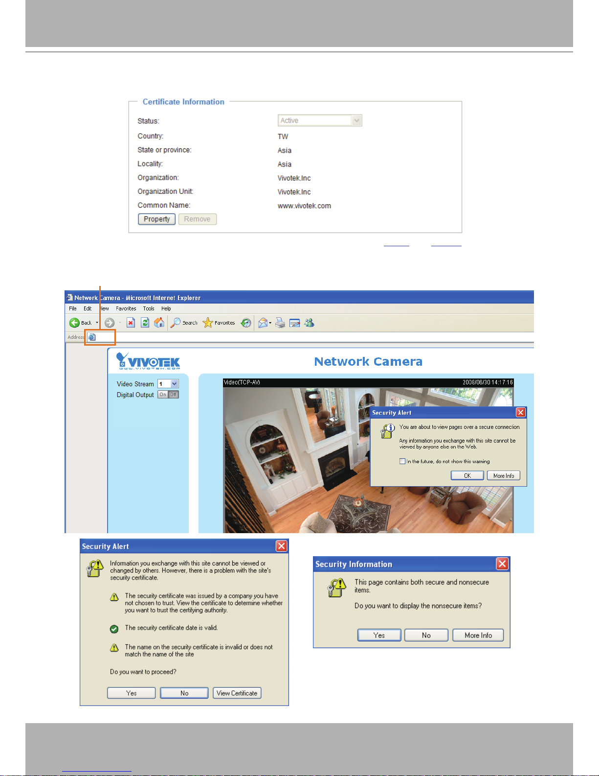
4. The Certicate Information will automatically de displayed in the third column as shown below. You can
click Property to view detailed information about the certicate.
5� Click Home to return to the main page� Change the address from “http://” to “https://“ in the address
bar and press Enter on your keyboard� Some Security Alert dialogs will pop up� Click OK or Yes to
enable HTTPS�
https://192.168.5.151/index.html
https://
VIVOTEK - A Leading Provider of Multimedia Communication Solutions
30 - User's Manual
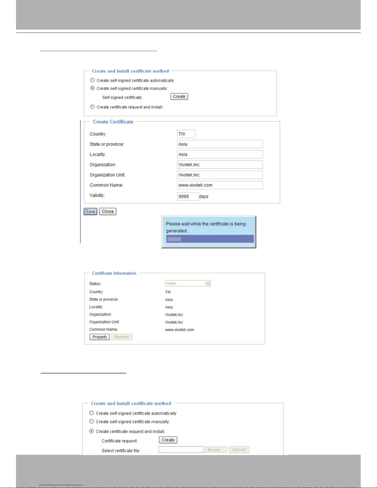
Create self-signed certificate manually
1� Select this option�
2� Click Create to open the Create Certicate page, then click Save to generate the certicate.
3. The Certicate Information will automatically be displayed in the third column as shown below. You
can click Property to see detailed information about the certicate.
Create certificate and install : Select this option if you want to create a certicate from a certicate
authority�
1� Select this option�
2� Click Create to open the Create Certicate page, then click Save to generate the certicate.
 Loading...