

ViewSonic VB50HRTV, VSACC23126-1M User Manual
VB50HRTV
User Guide
Guide de l'utilisateur
Manual de instucciones

1
Table of Contents
Copyright c ViewSonic Corporation, 2000. All rights reserved.
Macintosh and Power Macintosh are registered trademarks of Apple
Computer, Inc.
Microsoft, Windows, Windows NT, and the Windows Logo are registered
trademarks of Microsoft Corporation in the UnitedStates and other
countries.
ViewSonic, the three birds logo and OnView are registered trademarks
of ViewSonic Corporation. VESA is registered trademark of the Video
Electronics Standards Association. DPMS and DDC are trademarks of
VESA.
Disclaimer: ViewSonic Corporation shall not be liable for technical or
editorial errors or omissions contained herein; nor forincidental or
consequential damages resulting from furnishing this material, or the
performance or use of this product.
In the interest of continuing product improvement, ViewSonic
Corporation reserves the right to change product specifications without
notice. Information in this document may change without notice.
No part of this document may be copied, reproduced, or transmitted by
any means, for any purpose without prior written permission from
ViewSonic Corporation.
.
Electronic Warranty Registration
To meet your future needs, and to receive any additional product information as it
becomes available, please register your tuner box's warranty on the internet at
http: //www.viewsonic.com
FOR YOUR RECORDS
The serial number of this product is on the bottom of the tuner box.
Write the serial number in the space below and keep this guide as a
permanent record of your purchase to aid in identification in the
event of theft or loss.
Model Name: ViewSonic VB50HRTV
Model Number: VSACC23126-1M
Serial Number: ______________________
Purchase Date: ______________________
E
n
g
l
i
s
h

2
Table of Contents
Product Features
With advanced video processing technology, the TV, Composite, VIDEO, SVIDEO signal can be displayed on a PC monitor.
Up to quadruple scan conversion (15.75 KHz to 31.5-60.0 KHz).
View external video on a PC monitor (CRT or LCD).
The audio signal coming from PC can pass through to PC speakers.
Full screen, true color display.
Built-in TV tuner for receiving terrestrial or cable TV.
Easy operation - With one button to switch signals coming from composite
VIDEO, S-VIDEO, CABLE/TV or PC.
Automatic channel scan to detect the program channels.
On Screen Display operation with IR remote controller.
MTS and SAP supported for NTSC system.
Important Notices
Avoid exposure the to direct sunlight or high temperatures.
Avoid exposure the to moisture or high humidity.
Do not attempt repair yourself. Your warranty dose not cover repair or
attempted repair by anyone not authorized by Viewsonic.
If your
VB50HRTV
VB50HRTV
VB50HRTV will not be used for a long period of time, unplug and
remove the batteries from the remote control.
Congratulations on your purchase of ViewSonic . With , you
can use your computer monitor to view CATV, VCR, DVD or play video games.
The system set up is easy and there are no additional requirements for hardware
or software, just plug and play.
VB50HRTV VB50HRTV
E
n
g
l
i
s
h

3
Introduction
Chapter 1 Introduction
Package Contents
Chapter 2 Installation
VB50HRTV
VB50HRTV
System Installation
Chapter 3 Operation Instruction
Chapter 4
....................................................................................................
2.1 Product Overview...............................................................................................
2.1.1 ............................................................................
2.1.2 .............................................................................
2.2 ............................................................................................
2.2.1 Analog TV and A/V device connection.....................................................
2.2.2 Connect to remote signal............................................................................
2.2.3 Extend wiring
3.1 .......................................................................................................
3.2 Remote ..................................................................................................
3.3 ...............................................................................................
3.3.1
3.3.2
Troubleshooting.........................................................................................................
Front view of
Rear view of
.................................................................................................
Initial Setting
Control
Advanced Setting
MAIN MENU..................................................................................................
PICTURE setting..........................................................................................
3.3.3 SOUND setting.............................................................................................
3.3.4 OSD setting...................................................................................................
3.3.5 PREFERENCE setting.................................................................................
Including RESOLUTION and INPUT SIGNAL selection
3.3.6 CHANNEL setting.........................................................................................
Troubleshooting
Appendix A: Specifications......................................................................................
Appendix B:Limited Warranty................................................................................
Appendix C:FCC Information................................................................................
4
5
5
6
7
7
8
11
11
21
9
10
17
11
12
13
14
19
20
Table of Contents
10
22
Eng
lish
4
Installation
Package Contents
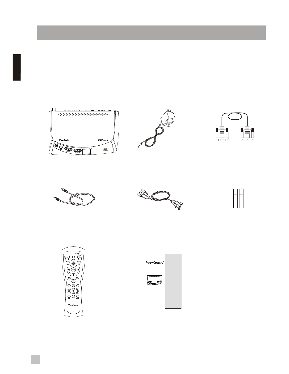
As you unpack the , you will find the following items:
If any items are missing, contact your reseller.
VB50HRTV
1. VB50HRTV
2. Power supply
3. VGA cable
4. Audio cable 5. A/V cable
7. Remote control
6. AAA batteries
Chapter 1 Introduction
8. User manual
E
n
g
l
i
s
h
VB50HRTV
User Guide
Guide de l'utilisateur
Manual de instucciones
5
Installation
Chapter 2 Installation
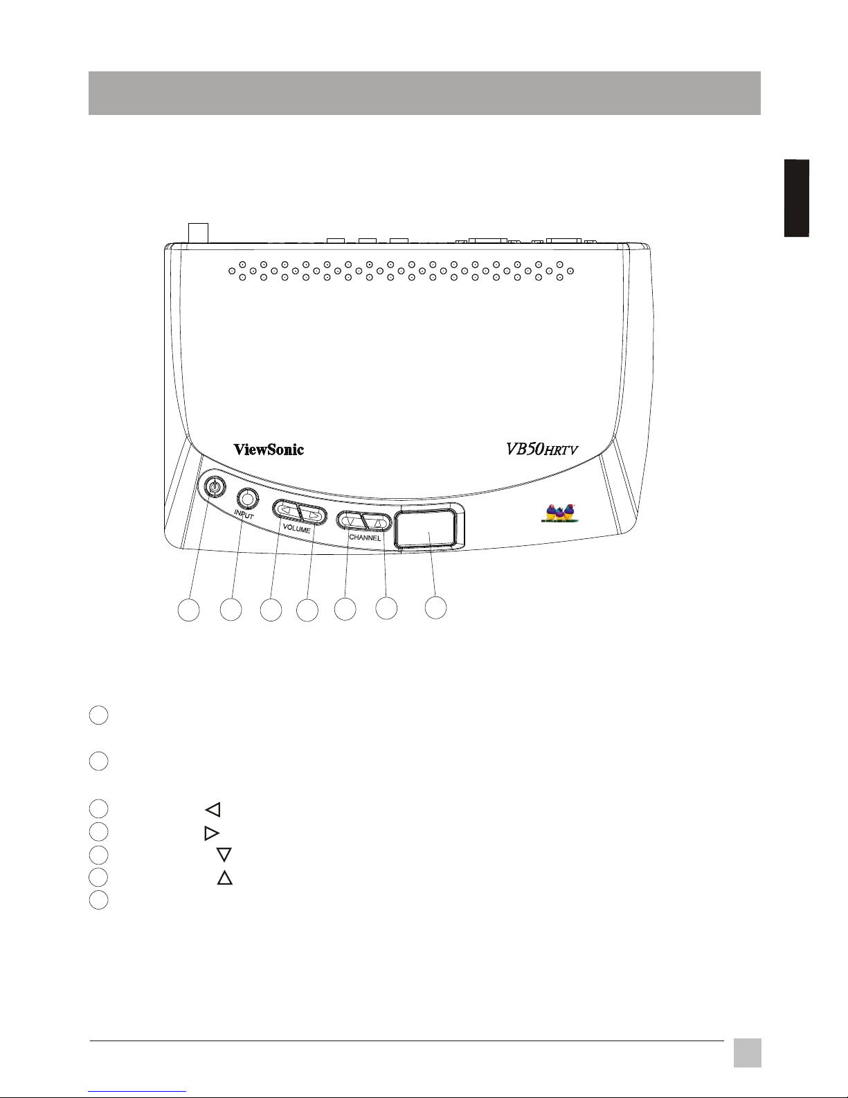
2.1.1 Front view of VB50HRTV
2.1 Product Overview
POWER : Use to turn unit on or off. The is in standby mode when
power is off.
VB50HRTV
INPUT : Select -VIDEO, S-VIDEO, CABLE PC. Press the "INPUT"
button to switch the signals between C
C /TV,or
-VIDEO,S-VIDEO,CABLE/TV, or PC.
VOLUME : Decreases the sound volume.
VOLUME : Increases the sound volume.
CHANNEL : Selects the next lower channel.
CHANNEL : Selects the next higher channel.
Power indicator and IR(infrared) receiver : Green LED indicates the status of
power and IR receiver.
1
2
3
4
5
6
7
1
2
3
4
5
6
7
Eng
lish
6
Installation
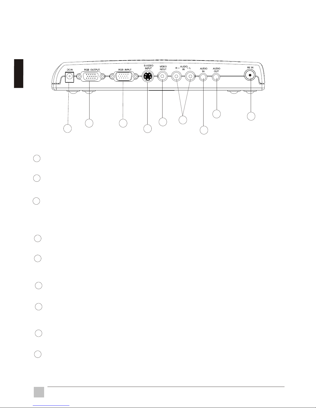
2.1.2 Rear view of VB50HRTV
1
2
3
4
5
6
7
8
9
RF IN (VHF/UHF)
Connect to antenna or cable TV signal.
AUDIO OUT
Connect the AUDIO OUT to your PC speakers.
AUDIO IN
Connect the audio cable from your sound card to the AUDIO IN port on the
B50HRTV
is not in use.
AUDIO (Left & Right) IN
Connect the external AUDIO IN to the
VIDEO INPUT
Connect the external video from a VCR, Laser Disk, V8 or video game to the
VIDEO INPUT port.
S-VIDEO INPUT
Connect the external S-video to the S-VIDEO INPUT port.
RGB INPUT
Using the 15-pin VGA cable provided, connect one side to the VGA output on
your PC and the other side to the RGB INPUT of your VB50HRTV.
RGB OUTPUT
Connect your 15 pin monitor connector to the RGB output.
DC IN
Connect to a 12V power supply.
VB50HRTV. Your PC speakers will output an audio signal when the V
VB50HRTV.
1
2
3
4
5
6
7
8
9
E
n
g
l
i
s
h
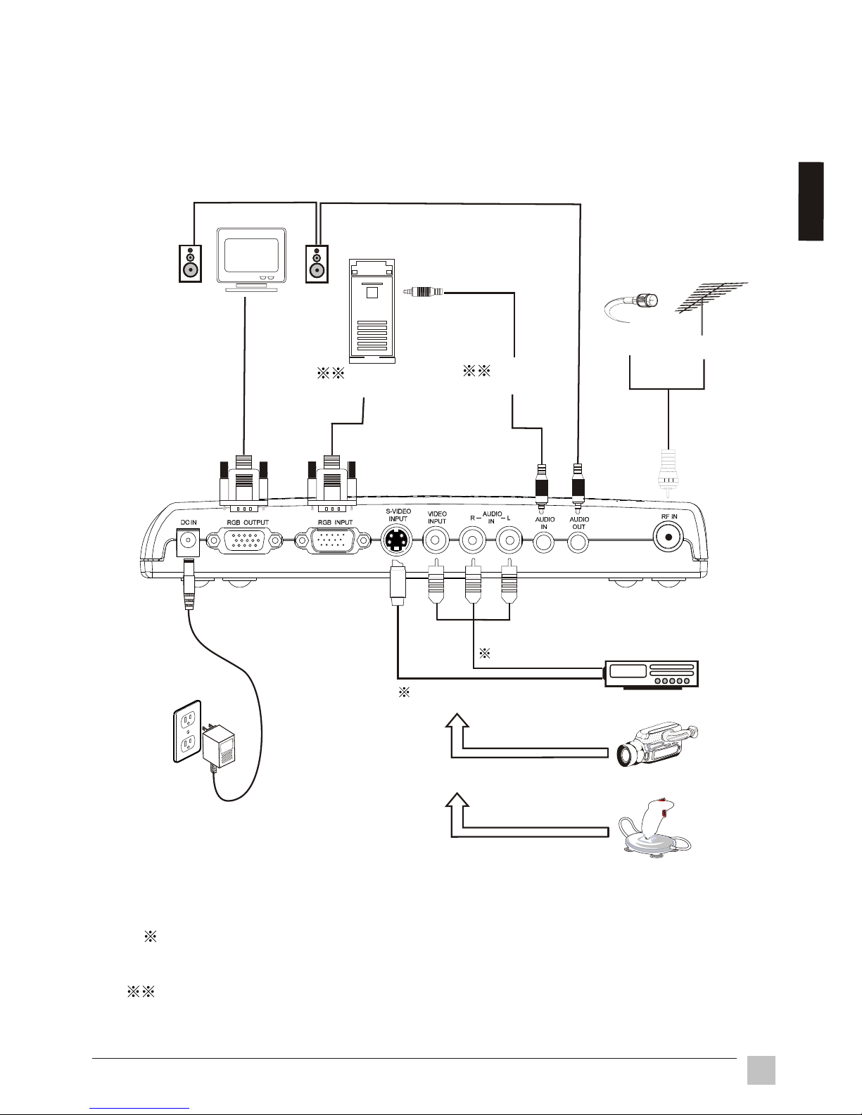
2.2 System Installation
Please refer to the example closest to your configuration.
2.2.1 Analog TV and A/V device connection
Audio/Video connection:
For audio connection, use RCA audio(L+R) connectors. For video connection, use
either RCA video connectors or S-Video connectors.
Disregard PC connections if you are only connecting your VB50HRTV to a monitor.
Speaker
Cable
Antenna
RGB output
from PC
Monitor
DVD/VCR/LD/IRD
Audio output
from PC
Camera
Video game
Adapter
RCA A/V cable
S-VIDEO cable
WARNING: Turn off all devices before you begin.
7
Installation
Eng
lish
Note: Power indicator will flashing a short period when you plug the DC IN adapter. Press
"Power" key will light the Power indicator.
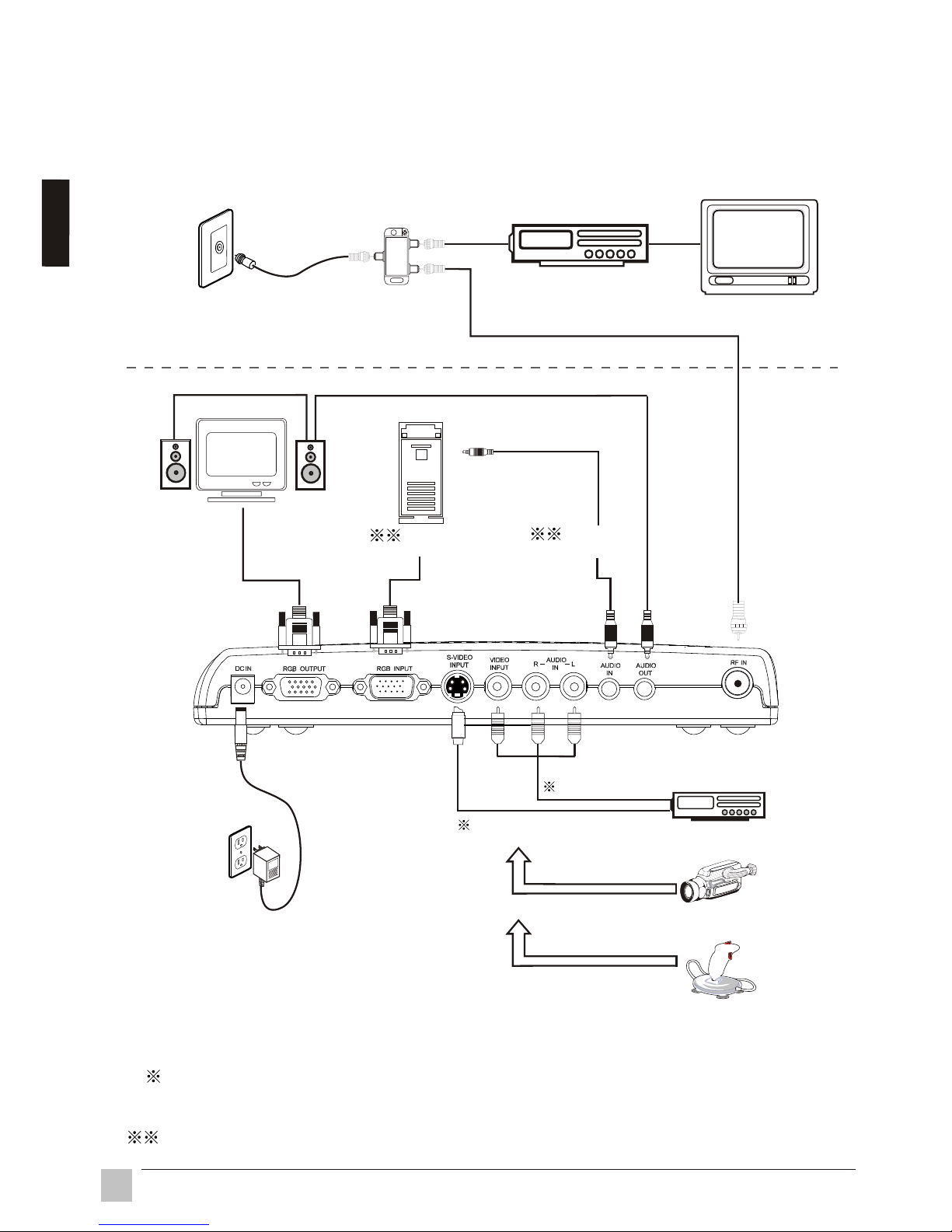
2.2.2 Connect to remote signal
If you must connect to a cable outlet or antenna located someplace other
than your setup area, use the following examples:
Cable or antenna
outlet
TV
Adapter
Two way splitter
Camera
Video game
RCA A/V cable
S-VIDEO cable
VCR / Cable box
DVD/VCR/LD/ IRD
Speaker
RGB output
from PC
Monitor
Audio output
from PC
WARNING: Turn off all devices before you begin.
Audio/Video connection:
For audio connection, use RCA audio(L+R) connector. For video connection, use
an RCA video connector or as S-Video connector.
Disregard PC connections if you are only connecting your VB50HRTV to a monitor.
8
Installation
E
n
g
l
ish
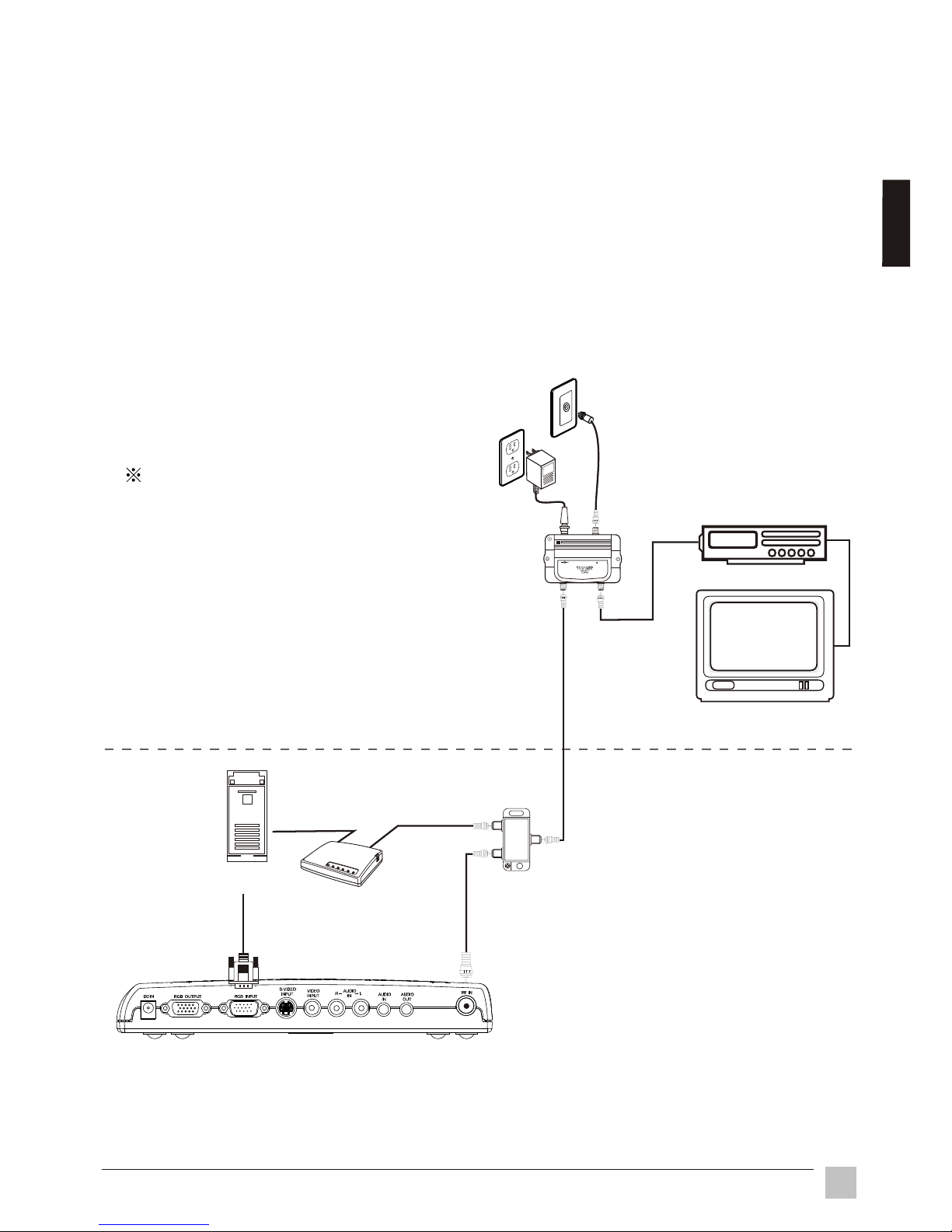
TV
OUT+7dB
OUT+7dB
12 ~16VDC
200mA
INPUT
If your setup is not close to the signal source, it is recommended to install a
indoor video amplifier to improve the signal. Indoor video amplifiers are
available at your local electronics store.
Note:
Omit the splitter connection in the following figure if there is no cable modem
present in your setup.
Two way splitter
Cable modem
Indoor Amp.
Cable or antenna
outlet
VGA output
from PC
(PC)
The best location of an
indoor amplifier is near a
television.
2.2.3 Extended wiring
VCR / Cable box
AC outlet
9
Instruction
Eng
lish
Chapter 3 Operation Instruction
3.1 Initial Settings
All the function settings for the VB50HRTV unit are controlled by the remote
control.
Steps:
1. Install 2 AAA batteries into remote control.
2. Turn on unit.
3. Press the "INPUT" button to select signal source.
4. Press the "SCAN" button to scan and memorize program channels.
5. After the auto scan is finished, please press channel " "," " , or channel
number keys to select a channel.
10
Operation Instruction
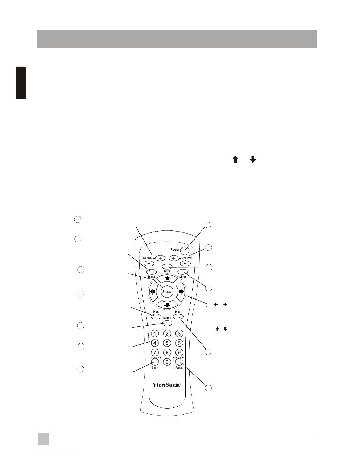
3.2 Remote Controls
1
Recall
Displays the last selected
channel
Input
C-VIDEO, S-VIDEO
, CABLE/TV, PC
Select input sources of :
Scan
Scan program channels
automatically and save
scanned programs
0~9 Number Keys
Used to select cable TV
or VHF/UHF program
2
3
4
5
6
7
8
9
10
Adjust the selected item on
Menu or adjust the volume
when Menu is not in use.
Press to select desired item on
Menu or select channels up or
down when Menu is not in use.
MTS
Select MTS of MONO,
STEREO, SAP
11
Res
Select resolution of
1024x768, 800x600
and 640x480
12
13
14
Volume+ / Volume -
Adjust the volume
Power
Switch between power-on
and power-off
Menu
Display the main menu
Mute
Turn the sound on/off
Select
Select the currently
highlighted menu item
Exit
Exit the current menu selection
and return to the parent menu.
Press this key repeatedly to close
all menus
Channel+ / Channel-
Select channels up or down
En
g
l
i
s
h
11Operation Instruction
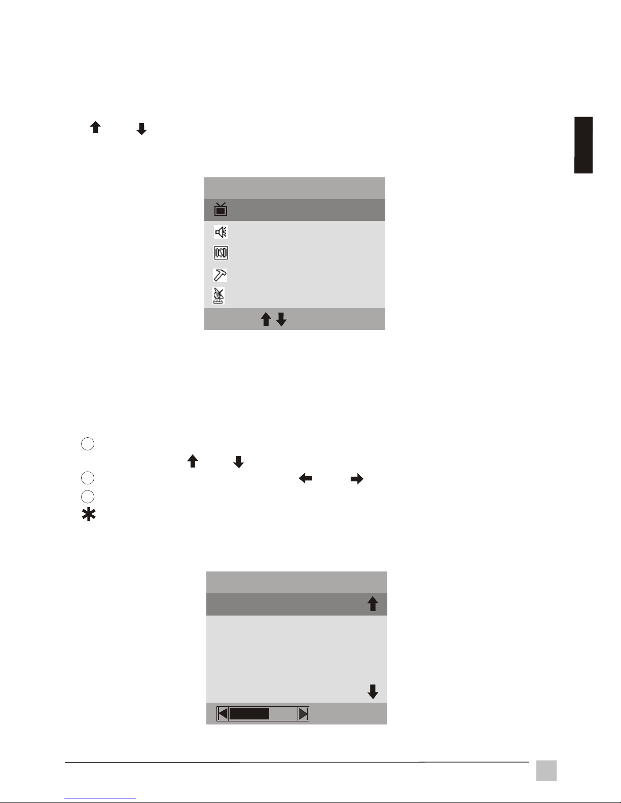
3.3.1 MAIN MENU
3.3 Advanced Settings
The MAIN MENU displays when you press "Menu". Press the up/down arrows
(" " or " " ) to highlight a menu option, then press "Select" to enter the SubMenu.
PICTURE Sub-Menu provides BRIGHTNESS, CONTRAST, SATURATION,
SHARPNESS, HUE adjustment modes and RESET.
BRIGHTNESS
CONTRAST
SATURATION
SHARPNESS
PICTURE
HUE
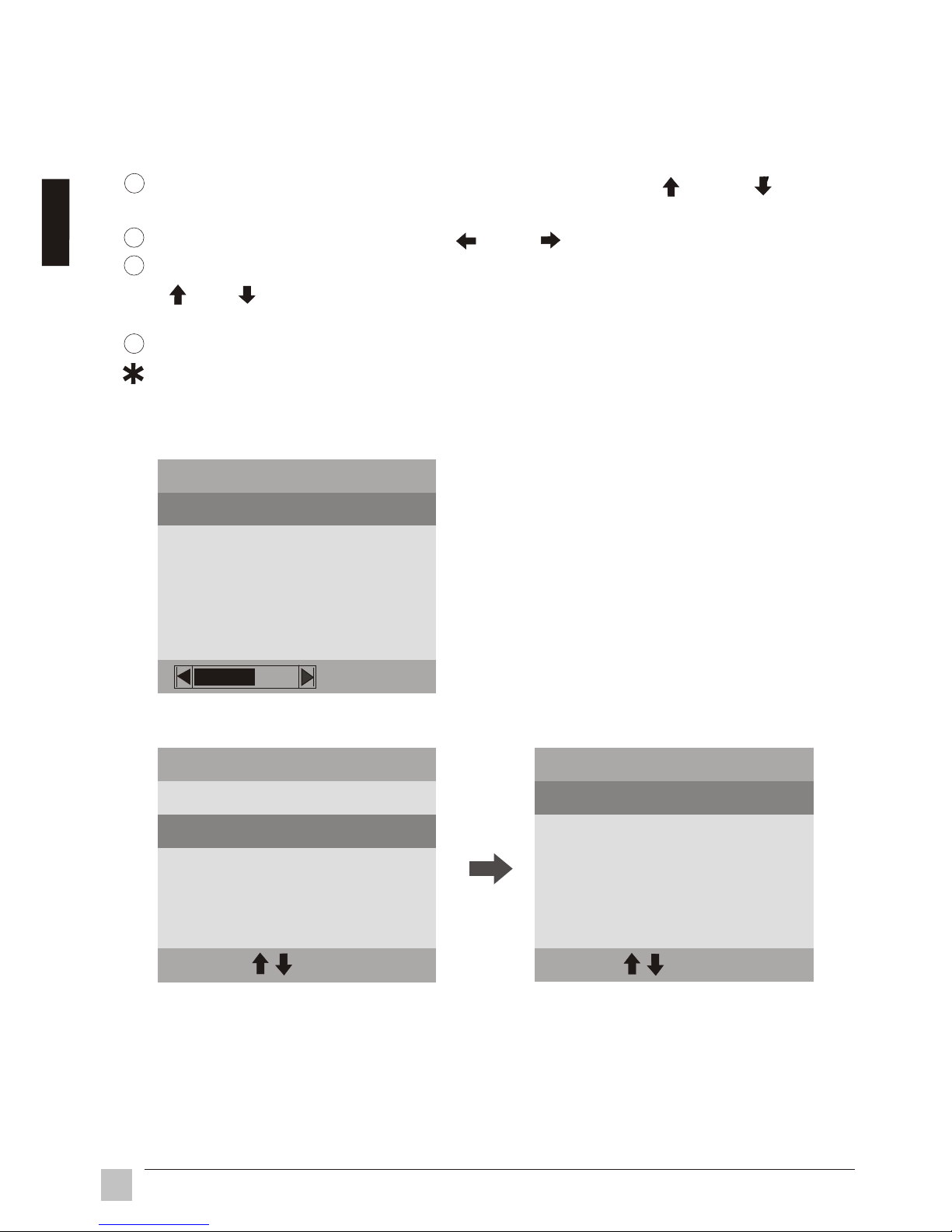
3.3.2 PICTURE settings
To select BRIGHTNESS, CONTRAST, SATURATION, SHARPNESS or
HUE, press " " or " " up/down arrows.
To adjust selected item, press " " or " " left/right arrows.
Press "Exit" to return to the main menu.
Select RESET to return to factory settings.
1
2
3
MAIN MENU
PICTURE
SOUND
OSD
PREFERENCE
EXIT
SEL
CHANNEL
E
ng
lish
12
Operation Instruction
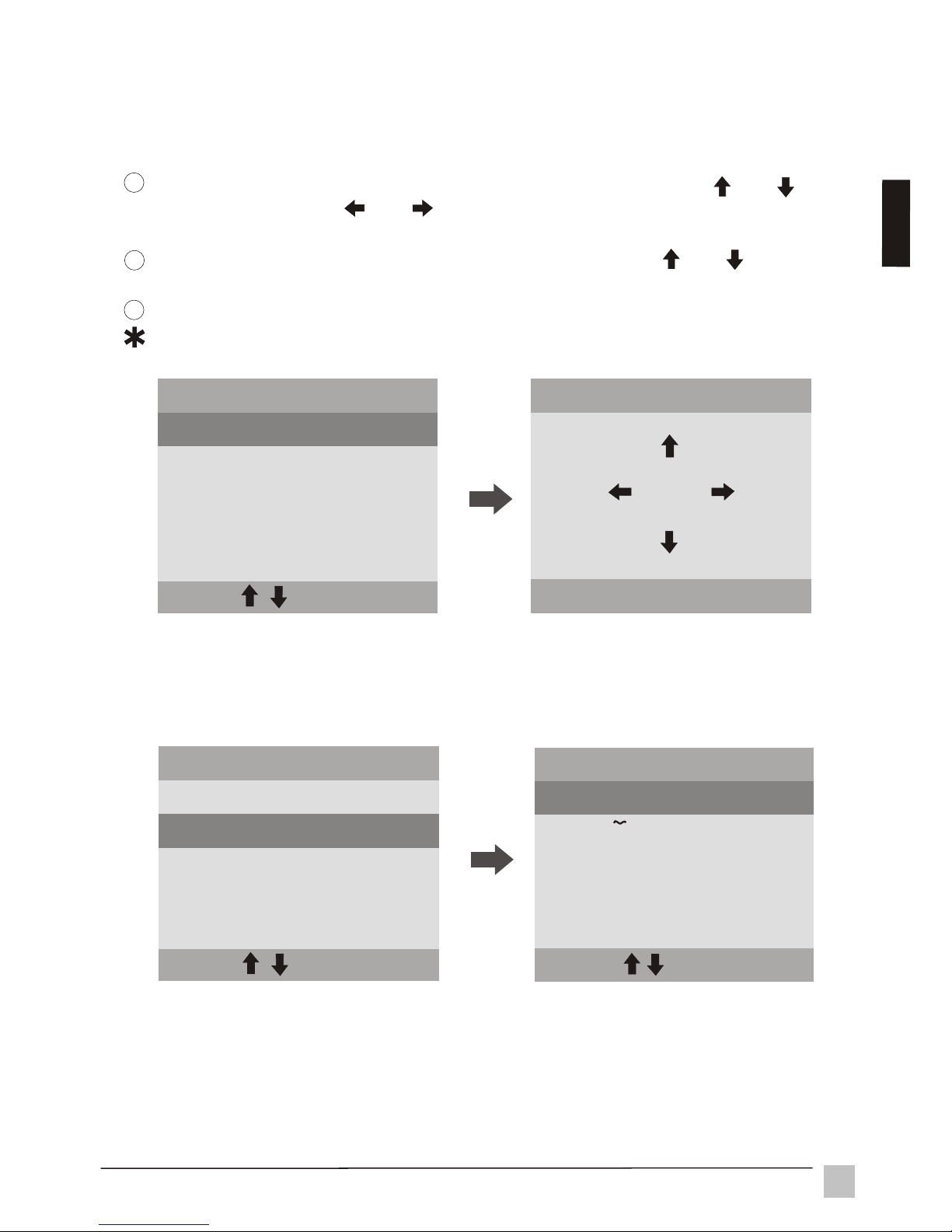
To select VOLUME, MTS, TREBLE or BASS, press " " or " "
up / down arrows.
To adjust selected item, press " " or " " left/right button.
To enter MONO, STEREO or SAP, press "Select" in MTS. Press
" " or " " up/down arrows to select an item, and press "Select" confirm
setting and return to the Sub-Menu.
Press "Exit" to return to the main menu.
Select RESET to return to factory settings.
SOUND Sub-Menu provides VOLUME, MTS, TREBLE, BASS adjustment
modes and RESET.
3.3.3 SOUND settings
VOLUME
MTS
TREBLE
RESET
SOUND
TREBLE
BASS
MONO
STEREO
EXIT
SEL
SAP
MTS
VOLUME
MTS
RESET
SOUND
TREBLE
BASS
EXIT
SEL
1
2
3
4
E
ng
lis
h
13
Operation Instruction
3.3.4 OSD (On Screen Display) settings
To enter OSD POSITION, press "Select" from OSD. Using " ", " "
up/down arrows or " ", " " left/right arrows to position the OSD menu on
the screen.
To enter LANGUAGE, press "Select" in OSD. Using " ", " " up/down
arrows to select the OSD language.
Press "Exit" to return to the main menu.
Select RESET to return to factory settings.
OSD POSITION
EXIT
SEL
OSD Sub-Menu provides OSD POSITION, LANGUAGE selected mode and
RESET.
1
2
3
OSD POSITION
RESET
OSD
EXIT
SEL
LANGUAGE
OSD POSITION
RESET
OSD
EXIT
SEL
LANGUAGE
E
n
g
l
i
sh
ENGLISH
EXIT
SEL
LANGUAGE
ITALIANO
DEUTSCH
ESPANOL
FRANCAIS
14
Operation Instruction
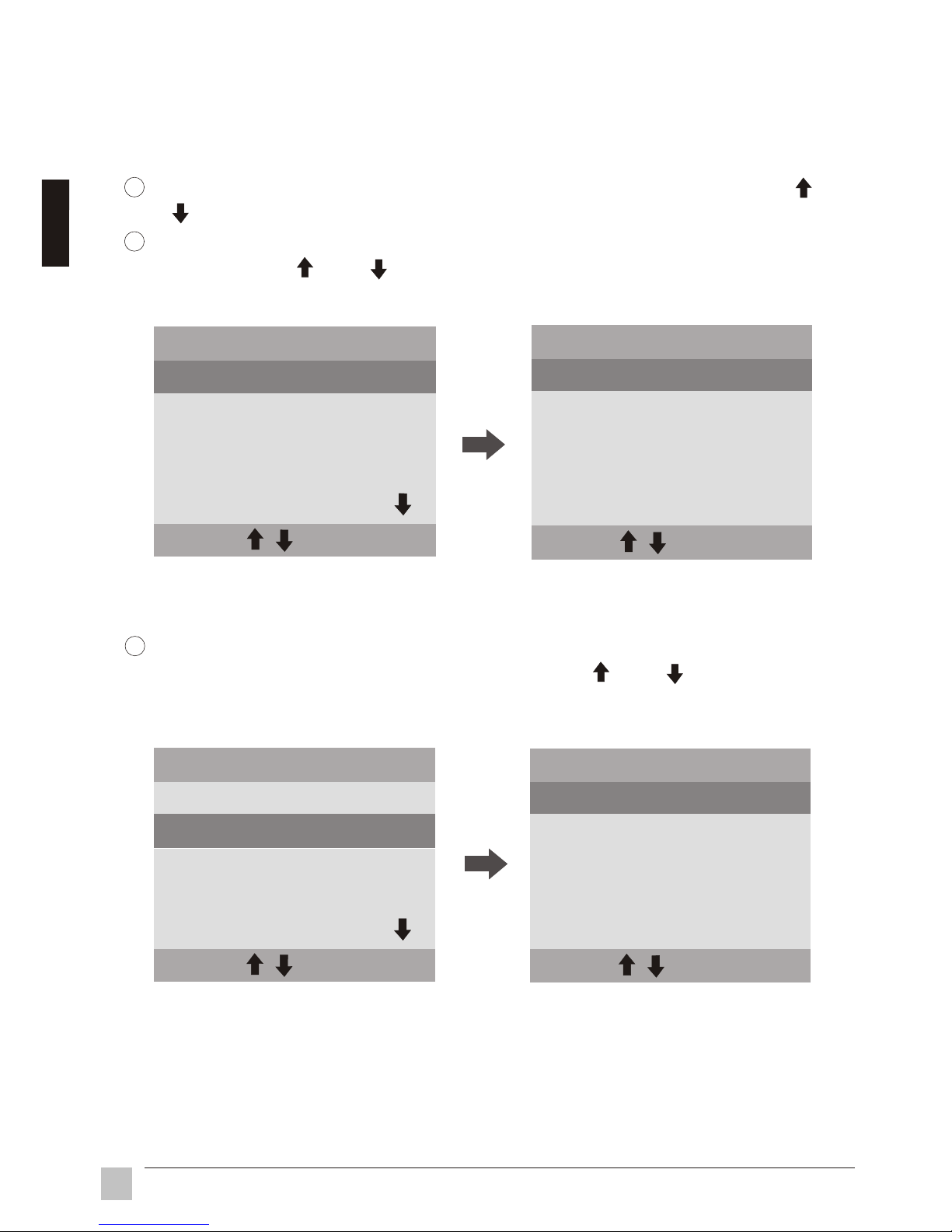
To enter "1024 x 768", "852 x 480", "800 x 600" or "640 x 480", press
"Select" from the RESOLUTION menu. Press " " or " " up/down to
select an item, then press "Select" to confirm and return to the Sub-Menu.
To select MODE, RESOLUTION, INPUT SIGNAL or SLEEP press " " or
" " up/down arrows.
To enter "NORMAL" or "SPORT" mode, press "Select" from the MODE
menu. Press " " or " " up/down arrows to select an item, then press
"Select" to confirm and return to the Sub-Menu.
PREFERENCE Sub-Menu provides MODE, RESOLUTION, INPUT SIGNAL,
SLEEP and RESET select modes.
3.3.5 PREFERENCE settings
1
2
INPUT SIGNAL
EXIT
SEL
PREFERENCE
TUNER INPUT
RESOLUTION
REFRESH
MODE
NORMAL
SPORT
MODE
EXIT
SEL
CONTINUED ON NEXT PAGE
1024x768
800x600
RESOLUTION
EXIT
SEL
640x480
852x480
INPUT SIGNAL
EXIT
SEL
PREFERENCE
TUNER INPUT
RESOLUTION
REFRESH
MODE
3
E
n
g
l
i
sh
 Loading...