

ViewSonic VS500-L, VS1000, VS1000-L, VS-500 User Manual
ViewSonic Manual
Battery Operated
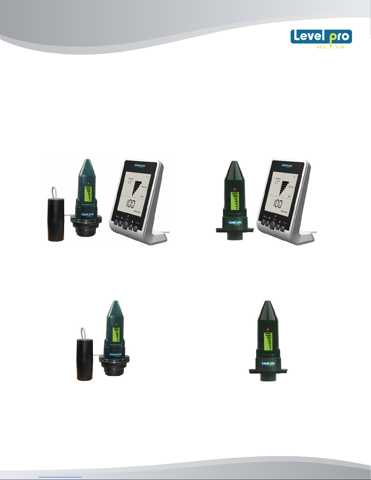
Ultrasonic Level Sensor (Models)
ViewSonic Level Sensor with
Leak Detection Switch + Remote Display
(Model VS1000-L)
ViewSonic Level Senor
c/w Leak Detection Switch
(Model VS500-L)
Read the user's manual carefully before starting to use the unit or software.
Levelpro reserves the right to implement changes without prior notice.
ViewSonic Level Sensor
with Remote Display
(Model VS1000)
ViewSonic Level Sensor
(Model VS500)
www.iconprocon.com
ViewSonic
User Manual
ViewSonic Manual
1. INTRODUCTION
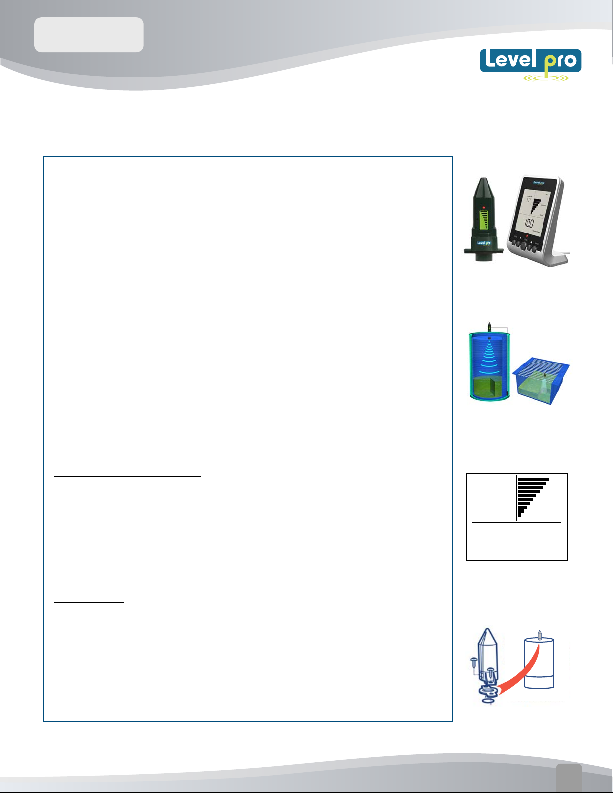
The ViewSonic Sensor is a battery operated ultrasonic liquid
level sensor that is capable of providing the user with instant
level indication at a glance. The ViewSonic Transmitter uses
ultrasonic (sound wave) technology to measure the distance
from the sensor face to the surface of the liquid in chemical
tank or sump, then back to sensor face; this is referred to as
(time of flight) As the liquid product inside the tank decreases
the distance that the senor measures increases accordingly.
The current level measurement can be viewed directly on the
LCD screen located on the sensor or via the remote display.
No wiring is required as the level data is wirelessly
transmitted to the remote display.
Gallons / Inches / %
After completion of programming the display calculates and
displays the amount of liquid remaining in your tank in
gallons, inches or as a percentage of the tank capacity. In
addition
Mounting
ROOM TEMPERATURE
°F
2O
65O
FULL
LIQUID LEVEL
EMPTY
Gal
The ViewSonic sensor can be mounted directly on the top of
the tank, drum, tote and is suitable for use with any plastic
or metal tank up to 10' (3m) in height, including double
walled tanks.
www.iconprocon.com
Easy to Install
01
ViewSonic
User Manual
2. Viewsonic Level – Features and Functions
13
1
2 3 4 5 6
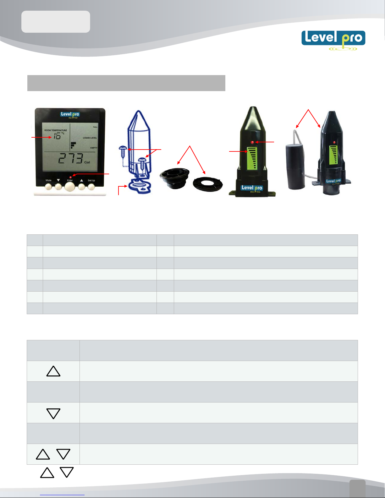
ViewSonic Features
1
LCD Display
2
MODE key
3
DOWN key
4
ENTER key
5
6
7
Key
UP
SETUP
Alarm Red LED
Key
8
9
7
10
8
9
10
11
12
13
11
12
10
ViewSonic Sensor
Self-tapping screws x 2
Weatherseal (Gasket)
Installation Fitting 2" , 1 1/2" NPT
ViewSonic Level display
ViewSonic Level + Leak Detection Switch
7
ViewSonic Key Functions
MODE
ENTER
SETUP
+
Note:
When the display is in 'NORMAL' mode press 'MODE' to move between the current and
the historical information screens.
Press 'UP' to move between screens when in 'NORMAL' mode to view Gal, In,
or % of current liquid level .Use it to increase a setting when in 'SETUP' mode.
The 'ENTER' key is used only during the 'SETUP' mode. Press to save the setting
shown on the display and then move automatically to the next 'SETUP' number.
Press 'DOWN' to move between screens when in 'NORMAL' mode to view Liquid
Level in Gal, In or %. Use it to decrease a setting when in 'SETUP' mode.
Press 'SETUP' for 3 seconds to enter 'SETUP'. When in
'SETUP', press 'SETUP' to exit from 'SETUP' mode.
When in 'NORMAL' mode, by press together and release, the screen will flash the
current tank configuration for 20 seconds.
PRESS
and HOLD UP or Down Arrows to Increase Selection Speed
www.iconprocon.com
02
ViewSonic
User Manual
LED
The red light above the 'ENTER' key flashes when there is an Alarm condition (see section 6)
TANK TYPE
A
B C
ROOM TEMPERATURE
°F
LIQUID LEVEL
H
W
18888
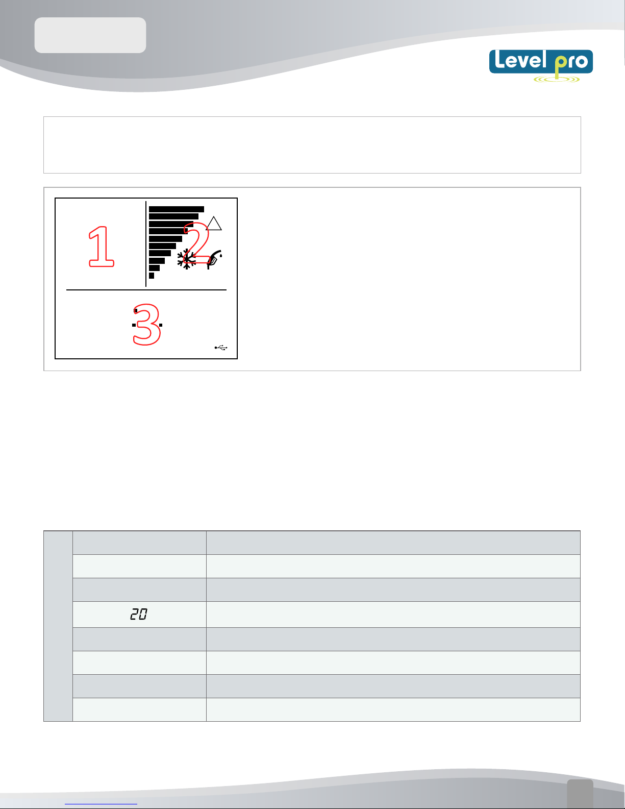
1.
Screen (1) displays Programming number, Tank Type -during normal operation
LEAK ALARM
%
in
Gal
/
FULL
!
EMPTY
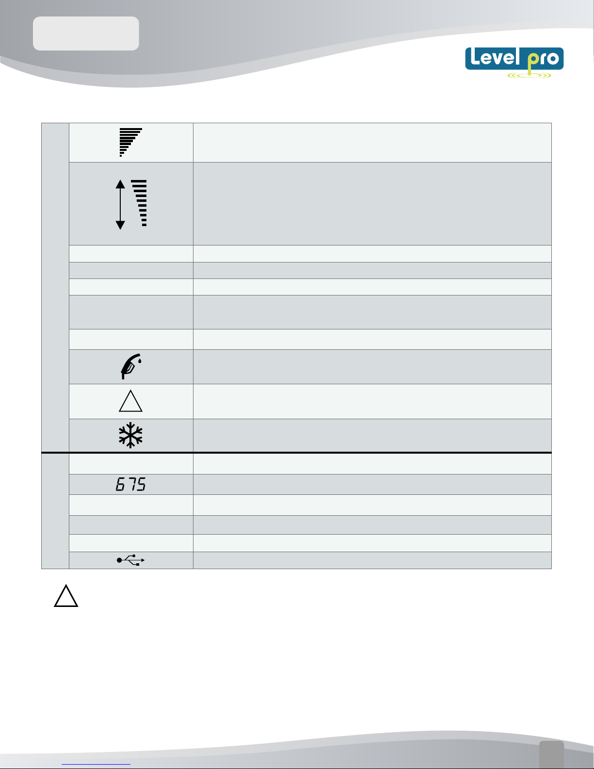
DISPLAY - SYMBOLS & INDICATORS
The Viewsonic Display displays valuable information during
normal use and during its initial setup and configuration for use
with your tank. T
indicated in the diagram.
he display contains three sections (1, 2, & 3) as
displays room temperature.
2.
Provide Liquid Level information including a visual bar-graph tank.
3.
Information about the remaining usable liquid in Gal/Inches or % Tank Volume
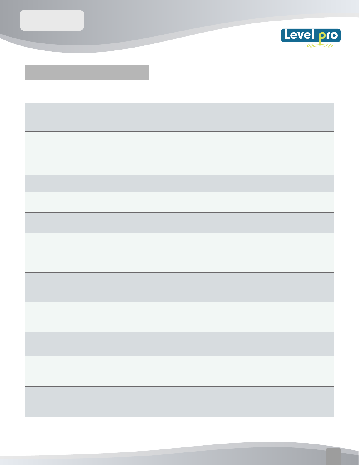
ViewSonic Display features
TANK TYPE
A,B,C
ROOM TEMPERATURE
1
in
H
W
Indicates the Tank Type being selected
A, B,C refers to tank shapes (see section 5)
The value displayed is the Room Temperature where display is located
Numeric display - Shows the Room Temperature in normal mode e.g 20.
The value displayed is temperature in degrees Farenheit°F
The value displayed is in INCHES
The value displayed is the Tank Height ( Tanks A, B, C)
The value displayed is the tank width-(tank types B & C Only)
www.iconprocon.com
03
ViewSonic
User Manual
ViewSonic Monitor Display:
Bargraph indicator of liquid level - each bar represents 10% of tank height
ViewSonice Transmitter Display:
Tanks 10 ft (3m ) in height or greater - each bar represents 10 % of
tank height
2
3
FULL
LIQUID LEVEL
EMPTY
LEAK DETECTION
ALARM
TANK LOW BATTERY
!
%
Inches
Gallons
Time
Indicates the 'Full' level of tank/drum being measured
Indicates the LCD display bargraph current liquid level
Indicates the 'Empty' level of the tank/drum being measured
The flashing of the LED light and LCD bars indicates a leak has been
detected.
The ViewSonic Transmitter battery needs to be changed. (See page 11)
Flashing - Indicates that the liquid IeveI in the tank is at 10% or below of
tank height. (Appears on both the Viewsonic Display and Transmitter)
Flashing - There is a problem with the RF signal from the ViewSonic Sensor
(Appears on both the Display and Sensor)
The temperature is close to or below the limit of operation of the ViewSonic
Sensor - the accuracy and battery life of the sensor may be affected.
The value displayed is the % of liquid remaining in the tank.
Numeric display - used to show numeric values
Displayed value in Inches
Displayed value in Gallons
The value displayed in 24 Hour Clock
Note : Reset Button located on back of Viewsonic Display
!
USB data connection.
www.iconprocon.com
04
ViewSonic
User Manual
3.PRODUCT INFORMATION
TECHNICAL SPECIFICATIONS:
Min.Height : 1.6 ft ( 0.5m)
Tank Size
Displays
Audible Alarm Audible alarm sounds every 60min (hourly) when the tank level is low
Max. Height: 10 Ft (3m)
Max. Ta
Multi-function LCD display including :
nk Volume: 5200 Gal (19999L)
• 10 bar-graph level indication on both ViewSonic Display and Sensor
• Display of various current and historical values (ViewSonic
• Red LED provides low level indication less than of liquid remaining
Display only)
Max communication
distance
Wireless
Communications
Power Supply - 3V LiMn cell, CR2450
Power Supply for
Display
Battery Life
Dimensions Sensor: 5.5" X 2.7" X 1.6" Display: 4.72" X 3.5" X 2"
Max and Min
Operation
(Transmitter)
Typically 200 Ft in normal ‘line of sight’ conditions
433MHz FM transmission (EN300-220)
120 VAC, 50-60 Hz, meets EN60950-1
Sensor : > 5 years (estimated life)
Display Monitor – approx 3yr of data
retention if display is not plugged in
Operating temperature range: -20°C to +60°C
Operating Humidity : 0 - 95% non-condensing
Hole size for
Fitting
Transmitter :
1.25" diameter
www.iconprocon.com
05
 Loading...