


Encore |
Woodburning Stove |
Model 2550
Homeowner’s
Installation and
Operating Manual
SAFETY NOTICE: IF THIS APPLIANCE IS NOT PROPERLY INSTALLED, OPERATED AND MAINTAINED, A HOUSE FIRE MAY RESULT.
TO REDUCE THE RISK OF FIRE, FOLLOW THE INSTALLATION INSTRUCTIONS. FAILURE TO FOLLOW INSTRUCTIONS MAY RESULT IN PROPERTY DAMAGE, BODILY INJURY OR EVEN DEATH. CONTACT LOCAL BUILDING OFFICIALS ABOUT RESTRICTIONS AND INSTALLATION INSPECTION REQUIREMENTS IN YOUR AREA.
Do Not Discard This Manual: Retain for Future Use
2000956 1/07 Rev. 16
Encore Woodburning Stove
Welcome
Congratulations on your choice of a Vermont Castings Encore. With this purchase you have made a commitment to make the hearth a place of warmth, beauty, and comfort in your home. At CFM Corporation, we share that joy and appreciation for the hearth. You may be assured that your cast-iron Vermont Castings stove has been made with the utmost care and will provide you with many years of service.
As you become acquainted with your new stove or fireplace, you will find that its visual appearance is matched by its functionality, due to cast iron’s unique capability to absorb and radiate heat.
Also, CFM Corporation units are among the cleanest-burning wood stoves and fireplaces available today. As an owner of a Vermont Castings stove, you make a strong statement for pollution-free energy. Clean burning, however, depends on both the manufacturer and the operator. Please read this manual carefully to understand how to properly operate and maintain your stove or fireplace.
At CFM Corporation, we are equally committed to your satisfaction as a customer. That is why we maintain an exclusive network of the finest dealers in the industry. Our dealers are chosen for their expertise and dedication to customer service. They are factory-trained and knowledgeable about every CFM Corporation product. Feel free to contact your Authorized Vermont Castings Dealer anytime you have a particular question about your stove or its performance.
This manual contains valuable instructions on the installation and operation of your Vermont Castings stove. It also contains useful information on maintenance and assembly of this product. We urge you to read the manual thoroughly and to keep it as a reference.
Sincerely,
All of us at CFM Corporation
This manual describes the installation, operation, and maintenance of the Vermont Castings Encore Model 2550 catalytic-equipped wood burning heater. This heater meets the U.S. Environmental Protection Agency’s emission limits for wood heaters sold on or after July 1, 1990. Under specific test conditions this heater has been shown to deliver heat at rates ranging from 8,700 to 41,700 Btu/hr.
The Encore Model #2550 has been tested and is listed by Warnock Hersey International of Middleton, Wisconsin. The test standards are ANSI/UL-1482 and ANSI/UL-737 for the United States, and ULC S627 and CAN/CSA-B366.2 for Canada. The Encore is listed for burning wood. Do not burn other fuels. The Encore
is listed and approved for use in mobile homes in the United States only when installed with Vermont Castings Mobile Home Kit #3251.
We recommend that you hire a professional installer certified by the Wood Heat Education and Research Foundation (WHERF) or the Wood Energy Technical Training (WETT) to install your stove, or to advise you on the installation should you attempt to install it yourself.
Please read this entire manual before you install and use your new stove. Failure to follow instructions may result in property damage, bodily injury, or even death.
Proposition 65 Warning: Fuels used in gas, woodburning or oil fired appliances, and the products of combustion of such fuels, contain chemicals known to the State of California to cause cancer, birth defects and other reproductive harm.
California Health & Safety Code Sec. 25249.6
Table of Contents
Specifications ................................. |
3 |
Installation ...................................... |
4 |
Assembly...................................... |
18 |
Operation...................................... |
19 |
Maintenance................................. |
27 |
Appendix: Catalytic Combustor.... |
33 |
Replacement Parts....................... |
34 |
Accessories
Warming Shelves |
|
|
|
#1560 |
Classic Black |
#1562 |
Sand |
#1555 |
Biscuit |
#1565 |
Bordeaux |
#1556 |
Chestnut Brown |
#1566 |
Forest Green |
#1557 |
Ebony |
#1567 |
Midnight Blue |
#1558 |
Vt. Classic Green |
#1568 |
Suede Brown |
#0127 Sparkscreen
#0164 Bottom Heat Shield
#0173 Rear Heat Shield
#3257 Outside Air Adapter
#3251 Mobile Home Kit
#0191 Heat shields for the chimney connector
- Matching porcelain stovepipe
2 |
2000956 |
Encore Woodburning Stove
Specifications
Range of heat output................. |
8,700-41,700 Btu’s/Hr* |
|
Maximum heat output........................ |
|
47,000 Btu’s/Hr** |
EPA emissions ratings, g/h, catalytic |
.......................1.6* |
|
Area heated***............... |
Up to 1900 sq. ft. (175 sq. m.) |
|
Fuel size/type ..................... |
18020” 9450-500 mm) logs |
|
Fuel capacity ........................................... |
|
40 lbs. (18kg) |
Loading....................................................... |
|
Front or top |
Chimney connector: |
|
|
for 8” flue collar ....................... |
8” (203 mm) diameter |
|
for 6” flue collar ....................... |
6” (152 mm) diameter |
|
Chimney flue size: |
|
|
for 8” flue collar ....................... |
8” (203 mm) minimum |
|
for 6” flue collar ....................... |
6” (152 mm) minimum |
|
Flue exit position ....................... |
Reversible, top or rear |
|
Primary air... Manually set, thermostatically maintained
Secondary air ......................................... |
Self-regulating |
Ash handling system ..................... |
Removable ash pan |
Glass panel ......................... |
High-temperature ceramic |
Weight ................................................. |
350 lbs. (159kg) |
Width (leg-to-leg)..................................... |
27” (685 mm) |
Depth (leg-to-leg) .................................... |
15” (380 mm) |
Height to top of flue collar, (6” or 8”) |
|
Top exit.............................................. |
25¹⁄ ” (640 mm) |
Rear exit............................................ |
26¹⁄ ” (675 mm) |
*Under specific conditions used during EPA emissions testing.
**These values are based on operation in building code-conforming homes under typical winter climate conditions in New England. If your home is of nonstandard construction (e.g. unusually well-insulated, not insulated, built underground, etc.) or if you live in a more severe or more temperate climate, these figures may not apply. Since so many variables affect performance, consult your Vermont Castings’ Authorized Dealer to determine realistic expectations for your home.
|
18" |
|
|
|
Drawings Not to Scale |
|
|
(460mm) |
|
|
|
|
|
|
|
|
|
|
|
|

 3 " 21 "
 (83mm)
(545mm) 24" (610mm)
27" |
2" |
22 " |
|
(690mm) |
5" |
||
|
(50mm) |
(570mm) |
|
27" |
|
(130mm) |
|
|
15 " |
||
(685mm) |
|
|
|
|
(390mm) |
2 " (75mm) |
|
|
|
|
|
18 " |
|
|
|
(470mm) |
25 " |
|
23 " |
|
(640mm) |
|
|
25 " |
|
(595mm) |
|
Top exit |
|
||
(660mm) |
flue collar |
|
|
|
height |
|
|
7 " |
|
|
5 " |
(190mm) |
|
|
(135mm) |
27" |
|
15" |
|
(685mm) |
|
(380mm) |
|
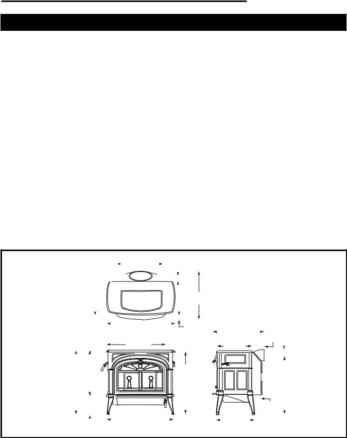
Fig. 1 Encore dimensions.
2000956 |
3 |
Encore Woodburning Stove
Installation
SAFETY NOTICE: IF YOUR ENCORE IS NOT PROPERLY INSTALLED, A HOUSE FIRE MAY RESULT. TO REDUCE THE RISK OF FIRE, FOLLOW THE INSTALLATION INSTRUCTIONS. CONTACT LOCAL BUILDING OR FIRE OFFICIALS ABOUT RESTRICTIONS AND INSTALLATION INSPECTION REQUIREMENTS IN YOUR AREA.
Before you begin an installation, be sure that:
•Your stove and chimney connector will be far enough from combustible materials to meet all clearance requirements.
•The floor protector is large enough and is constructed properly to meet all requirements.
•You have all necessary permits from local authorities.
Your local building official is the final authority for approving your installation as safe and determining that it meets local and state codes.
The metal label permanently attached to the back of every Vermont Castings’ stove indicates the stove has been tested to current UL and ULC standards, and gives the name of the testing laboratory. Clearance and installation information also is printed on the label. When the stove is installed according to the information both on the label and in this manual, local authorities in most cases will accept the label as evidence that the installation meets codes and can be approved.
However, codes vary in different areas. Before starting the installation, review your plans with the local building authority. Your local dealer can provide any additional information needed.
For any unresolved installation issues, refer to the National Fire Protection Association’s publication ANSI/NFPA 211 Standard for Chimneys, Fireplaces, Vents and Solid Fuel Burning Appliances. For Canada, the equivalent publication is CSA CAN-B365 Installation
Code for Solid Fuel Burning Appliances and Equipment. These standards are the basis for many national codes. They are nationally recognized and are accepted by most local authorities. Your local dealer or your local building official may have a copy of these regulations.
IMPORTANT: FAILURE TO FOLLOW THESE INSTALLATION INSTRUCTIONS MAY RESULT IN A DANGEROUS SITUATION, INCLUDING A CHIMNEY OR HOUSE FIRE. FOLLOW ALL INSTRUCTIONS EXACTLY, AND DO NOT ALLOW MAKESHIFT COMPROMISES TO ENDANGER PROPERTY AND PERSONAL SAFETY.
Outside Air
In some modern, super-insulated homes, there is inadequate air for combustion because of insufficient air infiltration into the building. Such air enters a home through unsealed cracks and openings. Exhaust fans for kitchen or bath can compete with the stove for available air and compound the problem.
When poor draft is caused by a low infiltration rate, opening a ground floor window on the windward side of the house and in the vicinity of the stove will usually alleviate the problem.
Another solution is to install a permanent outside air supply to the stove and/or room. In fact, bringing air for combustion from outside the home directly to the air inlet of the stove is required for new construction in some areas.
Pressure variations within the house do not affect a stove equipped with an outside air supply, and improved stove performance often results. An Outside Air Adapter Kit for the Encore is available from your local Vermont Castings dealer.
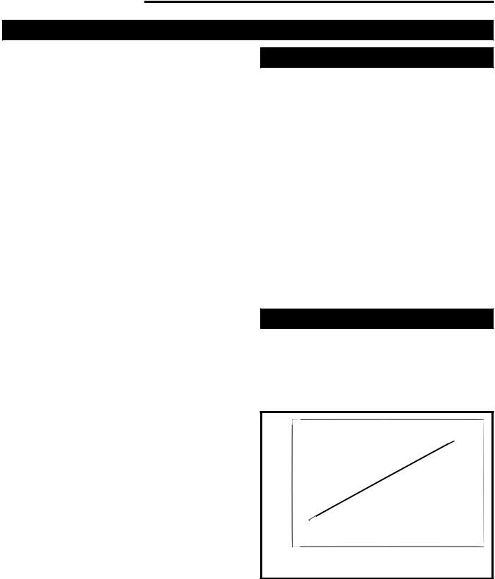
Chimney Height
Altitude affects chimney performance. When using a 6” flue collar on the Encore, refer to Figure 2 for suggested chimney heights at various altitudes. Chimney height should be measured from the flue collar to the top of the chimney. The recommended minimum chimney height is 16’ (4.9m).
|
30 |
Height |
25 |
20 |
|
|
15 |
0 2000 4000 6000 8000 10000 12000
ST491 Altitude
Fig. 2 Chimney height requirements for Encore when equipped with a 6” chimney.
4 |
2000956 |
What Kind of Chimney to Use
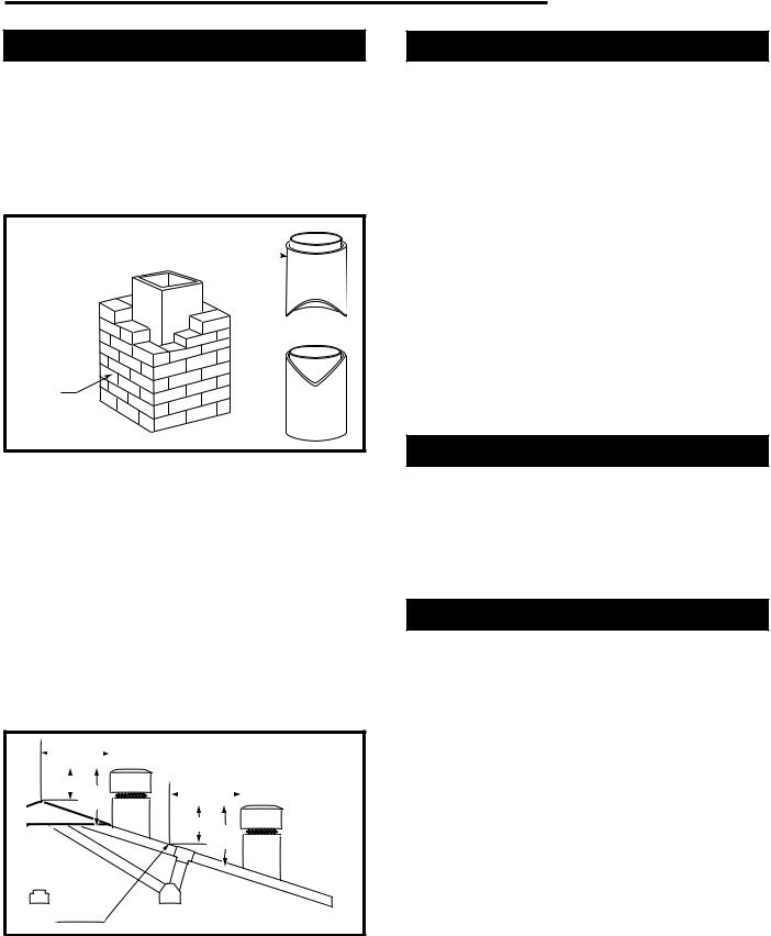
You must connect the Encore to a code-approved masonry chimney with a flue liner, to a relined masonry chimney that meets local codes, or to a prefabricated metal chimney that complies with the requirements for Type HT chimneys in the Standard for Chimneys, Factory-Built, Residential Type and Building Heating Appliance, UL 103. (Fig. 3) The chimney and chimney connector must be in good condition and kept clean.
A prefabricated doublewall insulated chimney 

A tile-lined masonry chimney
ST241
Fig. 3 Approved chimney types.
If you use an existing masonry chimney, it must be inspected to ensure it is in a safe condition before the stove is installed. Your local professional chimney sweep, building inspector, or fire department official will be able to inspect the chimney or provide a referral to someone who can.
The chimney should extend at least 3’ (914 mm) above the highest point where it passes through a roof, and at least 2’ (610 mm) higher than any portion of a building within 10’ (3 m). (Fig. 4)
For proper draft and good performance, any chimney used with an Encore should extend at least 16’ (5 m) above the flue collar of the stove.
0 To 10' |
|
2' Min. 3' |
0 To 10' |
Min. |
|
|
2' Min. 3' |
|
Min. |
Reference |
|
Point |
AC617 |
Fig. 4 The 2’-3’-10’ Chimney Rule.
Encore Woodburning Stove
Masonry Chimneys
An inspection of the chimney must confirm that it has a lining. Do not use an unlined chimney. The chimney should have no cracks, loose mortar, other signs of deterioration, and blockage. Repair any defects before the chimney is used with your stove.
Unused openings in an existing masonry chimney must be sealed with masonry to the thickness of the chimney wall, and the chimney liner should be repaired. Openings sealed with pie plates or wallpaper are a hazard and should be sealed with mortar or refractory cement. In the event of a chimney fire, flames and smoke may be forced out of these unused thimbles.
The chimney should be thoroughly cleaned before use.
A newly-built masonry chimney must conform to the standards of your local building code or, in the absence of a local code, to a recognized national code. Masonry chimneys must be lined, either with code-approved masonry or pre-cast refractory tiles, stainless steel pipe, or a code-approved, “poured-in-place” liner. The chimney’s clean-out door must seal tightly.
Prefabricated Chimneys
A prefabricated metal chimney must be one tested and listed for use with solid-fuel burning appliances to the High-Temperature (H.T.) Chimney Standard UL-103- 1985 (2100°F) for the United States, and High Temperature (650°C) Standard ULC S-629 for Canada.
DO NOT CONNECT THIS UNIT TO A CHIMNEY FLUE SERVING ANOTHER APPLIANCE.
Chimney Size
An Encore with an 8” (203 mm) flue collar is approved for venting into a masonry chimney with a nominal flue size of 8” x 8” (203 x 203 mm) or 8” x 12” (203 x
305 mm), and into a round flue with nominal flue size of 8” (203 mm). An Encore with a 6” (152 mm) flue collar is approved for venting into a masonry chimney with a nominal flue size of 8” x 8” (203 x 203 mm), and into a round flue with nominal flue of 6” (152 mm).
NOTE: When installed with a 6” flue collar, the Encore may not be operated with the front doors open.
Whatever the flue collar size, an Encore may be vented into larger chimneys as well. However, chimneys with liners larger than 8” x 12” (203 x 305mm) may experience rapid cooling of smoke and reduction in draft, especially if the chimneys are located outside the home. These large chimneys may need to be insulated or have their flues relined for proper stove performance.
Accessories to help make the connection between stainless steel chimney liners and your Encore are available through your local dealer.
2000956 |
5 |
Encore Woodburning Stove
Chimney Connector Guidelines
A chimney connector is the double-wall or single-wall pipe that connects the stove to the chimney. The chimney itself is the masonry or prefabricated structure that encloses the flue. Chimney connectors are used only to connect the stove to the chimney, as in Figure 5.
Double-wall connectors must be tested and listed for use with solid-fuel burning appliances. Single-wall connectors should be made of 24 gauge or heavier steel. Do not use galvanized connector; it cannot withstand the high temperatures that can be reached by smoke and exhaust gases, and may release toxic fumes under high heat. The connector may be 6” (152 mm) or 8 “ (203 mm) in diameter.
If possible, do not pass the chimney connector through a combustible wall or ceiling. If passage through a combustible wall is unavoidable, refer to the section on Wall
Pass-Throughs. Do not pass the connector through an attic, a closet or similar concealed space. The whole connector should be exposed and accessible for inspection and cleaning.
In horizontal runs of chimney connector, maintain a distance of 24” (610 mm) from the ceiling. Keep it as short and direct as possible, with no more than two 90° turns. Slope horizontal runs of connector upward 1/4” per foot (6 mm per meter) going from the stove toward the chimney. The recommended maximum length of a horizontal run is 3’ (1 m), and the total length should be no longer than 8’ (2.4 m). In cathedral ceiling installations, extend the prefabricated chimney downward to within 8’ (2.4 m) of the stove.
Wear gloves and protective eyewear when drilling, cutting or joining sections of chimney connector.
Double-wall Chimney Connectors
Information on assembling and installing double-wall connectors is provided by the manufacturer of the double-wall pipe. Follow the manufacturer’s instructions exactly as you assemble the connector and attach it to the stove and chimney. Using chimneys and connectors from the same manufacturer makes the assembly and installation straightforward.
NOTE: For installations using double-wall connectors, minimum clearances must conform to the listed clearances in the clearance chart on Page 14.
If the Encore is equipped with the 8” flue collar, an oval- to-round adapter will be needed. Double-wall oval-to- round adapters are available from some manufacturers. Your local dealer can help you select the right connector.
Single-wall Chimney Connectors
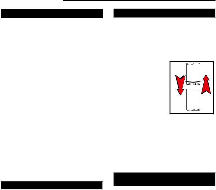
•Begin assembly at the flue collar of the stove. Insert the first crimped end into the stove’s flue collar, and keep each crimped end pointing toward the stove.
(Fig. 5)Using the holes in the flue collar as guides, drill 1/8” (3mm) holes in the bottom of the first section of chimney connector and secure it to the flue collar with three #10 x 1/2” sheet metal screws.
•Secure each joint between sections of chimney connector, including
telescoping joints, with at least three (3) sheet metal screws. The pre-drilled
holes in the top of each |
|
section of chimney con- |
|
nector serve as guides |
|
when you drill 1/8” (3mm) |
|
holes in the bottom of the |
|
next section. |
|
• Secure the chimney con- |
|
nector to the chimney. |
Fig. 5 the crimped end |
Instructions for various |
of the connector points |
installations follow. |
toward stove. |
•Be sure the installed stove
and chimney connector are correct distances from nearby combustible materials.
NOTE: Special slip pipes and thimble sleeves that form telescoping joints between sections of chimney connector are available to simplify installations. They often eliminate the need to cut individual connector sections. Consult your local dealer about these special pieces.
Securing the Single-wall Connector to a Prefabricated Chimney
Follow the installation instructions of the chimney manufacturer exactly as you install the chimney. The manufacturer of the chimney will supply the accessories to support the chimney, either from the roof of the house, at the ceiling of the room where the stove is installed, or from an exterior wall.
Special adapters are available from your local dealer to make the connection between the prefabricated chimney and the chimney connector. The top of such adapters attaches directly to the chimney or to the chimney’s ceiling support package, while the bottom of the adapter is screwed to the chimney connector.
These adapters are designed so the top end will fit outside the inner wall of the chimney, and the bottom end will fit inside the first section of chimney connector. When assembled in this way, any soot or creosote falling from the inner walls of the chimney will stay inside the chimney connector.
6 |
2000956 |
Chimney |
Flue |
|
|
Elbow |
Flue Liner |
|
Slip Pipe
Thimble
Standard
Connector 
Oval to
Round Adapter 
 Flue Collar
ST492
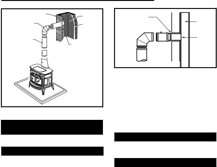
Fig. 6 An exploded view of the chimney connection in a freestanding masonry installation.
Securing the Single-wall Connector to a Masonry Chimney
Both freestanding masonry chimneys and fireplace masonry chimneys may be used for your installation.
Freestanding Installations
If the chimney connector must pass through a combustible wall to reach the chimney, follow the recommendations in the Wall Pass-Through section that follows.
The opening through the chimney wall to the flue (the “breech”) must be lined with either a ceramic or metal cylinder, called the “thimble”, which is cemented securely in place. Most chimney breeches incorporate
thimbles, but the fit must be snug and the joint between the thimble and the chimney wall must be cemented
firmly.
A special piece called the “thimble sleeve,” slightly smaller in diameter than standard connectors and most thimbles, will facilitate the removal of the chimney connector system for inspection and cleaning. Thimble sleeves should be available from your local dealer.
To install a thimble sleeve, slide it into the breech until it is flush with the inner flue wall. Do not extend it into the actual flue passage, as this could interfere with the draft.
Encore Woodburning Stove
Thimble Sleeve
Flue
Chimney Connector 
Keep
sleeve end flush
with flue tile
ST243
Fig. 7 The thimble, made of either ceramic or metal, must be cemented securely in place.
The thimble sleeve should protrude 1-2” (25-50mm) into the room. (Fig. 7) Use furnace cement and thin gasketing to seal the sleeve in place in the thimble. Secure the chimney connector to the outer end of the sleeve with sheet metal screws.
Without a thimble, a suitable length of chimney connector can be extended through the breech to the inner face of the flue liner, and cemented securely in place. Additional pieces of connector are then attached with sheet metal screws.
Fireplace Installations
The chimney connector may be connected to the chimney above the fireplace opening or through the fireplace.
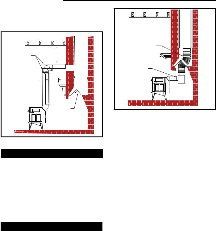
Above the Fireplace
The Encore may be connected to a chimney above a fireplace opening. (Fig. 8) In such installations, the
stove is positioned on the hearth in front of the fireplace and the chimney connector rises from the stove top and then angles ninety degrees back into the chimney. The chimney liner should extend to the point at which the chimney connector enters the chimney.
If the chimney connector from your installation enters the chimney above a fireplace, follow all the guidelines mentioned above for freestanding installations. In addition, give special consideration to the following points:
•Check the clearance between the stove and the chimney connector, and any combustible trim or the mantel. Use the necessary combination of mantel, trim, and connector heat shields to achieve the required clearances.
•Check the clearance between the chimney connector and the ceiling. If no heat shields are used, the clearance should be at least 24” (610 mm). To find out how much this clearance may be reduced with heat shields, refer to the clearance chart on Page 14.
2000956 |
7 |
Encore Woodburning Stove
• The fireplace damper must be sealed to prevent room air from escaping up the flue. However, it must be possible to re-open the damper to inspect or clean the chimney.
Chimney |
* |
|
Connector Shields |
||
|
* |
|
* Check |
Mantel |
|
These Clear- |
||
|
||
ances |
|
|
|
Seal this off |
|
ST244 |
|
Fig. 8 In this installation, the chimney connector is attached to the chimney above the fireplace opening.
Through the Fireplace
If your fireplace opening height is at least 26¹⁄" (675 mm), you may install an Encore through the opening using a “positive connection” kit, available from your local dealer. These positive connection kits ensure a tight fit between the stove flue collar and the chimney flue. (Fig. 9)
Fireplace installations, whether connected to the flue above or through the fireplace opening, have special clearance requirements to adjacent trim and the mantel. You’ll find the required safe clearances for Encore fireplace installations on Page 12.
Floor protection requirements also apply to fireplace installations. This information is on Page 10.
Wall Pass-Throughs
Whenever possible, design your installation so the connector does not pass through a combustible wall. If you are considering a wall pass-through in your installation, check with your building inspector before you begin.
Also, check with the chimney connector manufacturer for any specific requirements.
Accessories are available for use as wall passthroughs. If using one of these, make sure it has been tested and listed for use as a wall pass-through.
Flexible Connector
Mantel Shield 
Fireplace Adapter
Kit “Positive Connection”
ST245
Fig. 9 In this installation, the chimney connector enters the firepalce opening and then connects to the chimney.
In the United States, the National Fire Protection Association (NFPA) has established guidelines for passing chimney connectors through combustible walls. Many building code inspectors follow these guidelines when approving installations.
Figure 10 shows one NFPA-recommended method.
All combustible material in the wall is cut away from the single-wall connector to provide the required 12” (305mm) clearance. Any material used to close up the opening must be noncombustible.
Three other methods are also approved by the NFPA:
•Using a section of double-wall chimney with a 9” (229 mm) clearance to combustibles.
•Placing a section of chimney connector inside a ventilated thimble, which in turn is separated from combustibles by 6” (152 mm) of fiberglass insulating material.
•Placing a section of chimney connector inside a section of 9” (230 mm) diameter, solid-insulated, facto- ry-built chimney, with 2” (51 mm) of air space between the chimney section and combustibles.
In Canada, The Canadian Standards Association has established different guidelines. Figure 10 shows one method, in which all combustible material in the wall is cut away to provide the required 18” (457 mm) clearance for the connector. The resulting space must remain empty. A flush-mounted sheet metal cover may be used on one side only. If covers must be used on both sides, each cover must be mounted on noncombustible spacers at least 1” (25 mm) clear of the wall.
8 |
2000956 |
Wall Stud
Chimney
Connector
D |
T |
EFIAN |
|
12” Noncombustible
Material
Floor Protection
ST493
Fig. 10 An approved wall pass-through for the United States.
Your local dealer or your local building inspector can provide details for other approved methods of passing a chimney connector through a combustible wall in your area. In Canada, this type of installation must conform to CAN/CSA-B365, Installation Code for Solid Fuel Burning Appliances and Equipment.
NOTE: Do not vent your Encore into a factory-built (zero-clearance) fireplace. These appliances and their chimneys are specifically designed as a unit for use as fireplaces. It may void the listing or be hazardous to adapt them for any other use.
18” (460mm) clear space all around the pipe
T
ST494
Fig. 11 An approved wall pass-through for Canada.
DO NOT CONNECT AN ENCORE TO ANY AIR DISTRIBUTION DUCT OR SYSTEM.
Encore Woodburning Stove
Floor Protection
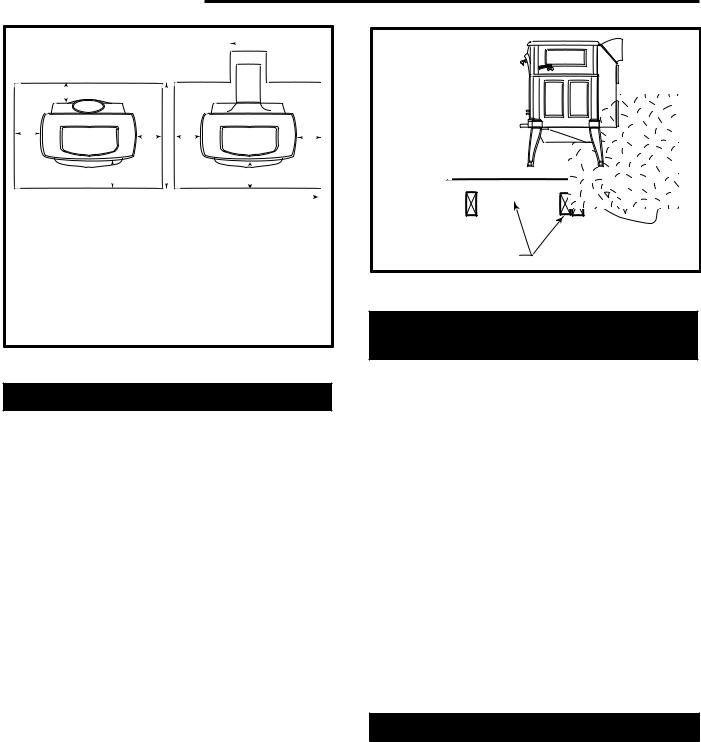
A tremendous amount of heat radiates from the bottom plate of your stove. The floor area directly under and around the stove will require protection from radiant heat as well as from stray sparks or embers that may escape the firebox.
Heat protection is provided through the use of a Vermont Castings Bottom Heat Shield #0164. Spark and ember protection must be provided by a floor protector constructed with noncombustible material as specified.
Most installations will require the bottom heat shield be attached. Only when the stove is placed on a completely noncombustible surface such as unpainted concrete over earth may it be used without the heat shield.
Even when the bottom heat shield is installed, you must provide special protection to the floor beneath. For installations with the heat shield attached, use a noncombustible floor protector such as 1/4” nonasbestos mineral board or equivalent, or 24 gauge sheet metal. The floor protector may be covered with a noncombustible decorative material if desired. Do not obstruct the space under the heater.
Protection requirements vary somewhat between the Untied States and Canada as follows:
U. S. installations the floor protector is required under the stove and must extend at least 16” (not including the ash lip) from the front of the stove (“F”, Fig. 12), and at least 6” from the sides and rear. (“D” and “E”, Fig. 12) It must also extend under the chimney connector and 2” to either side. (“C”, Fig. 12) For the 8” (203 mm) connector, the protector must be a minimum of 12” (305 mm) wide. For the 6” (152 mm) connector, the protector must be 10” (254 mm) wide. The protector must be centered under the connector.
To meet these requirements, a floor protector must be at least 39” wide and 44” deep.
In Canada: A noncombustible floor protector is required under the stove as well. The floor protector must extend 18” (457 mm) to the front (“F”, Fig. 12), and 8” (203 mm) from the sides and rear. (“D” and “E”, Fig. 12)
To meet these requirements, a floor protector must be at least 43” (1092 mm) wide and 48” (1219 mm) deep.
Floor protection also must extend under the chimney connector and 2” (51 mm) to either side. (“C”, Fig. 12) For the 8” (203 mm) connector, the protector must be a minimum of 12” (305 mm) wide. For the 6” (152 mm) connector, it must be at least 10” (254 mm) wide. The protector must be centered under the connector.
2000956 |
9 |
Encore Woodburning Stove
C 
D
B
E |
E |
E |
E |
FF

 A
A 

 A
A
U.S. Canada
A.39” 43” (1092 mm)
B.44” 48” (1219 mm)
C. |
12” |
12” |
(305 mm) |
8” Connector |
|
10” |
10” |
(255 mm) |
10” Connector |
D.6” 8” (203 mm)
E.6” 8” (203 mm)
F. |
16” |
18” (459 mm) |
ST500 |
Fig. 12 Required floor protector dimensions for both top-and rear-exiting stove.
Floor Protection for Fireplace Installations
Do not assume that your fireplace hearth is completely noncombustible.
Many fireplace hearths do not meet the “completely noncombustible” requirement because the brick or concrete in front of the fireplace opening is supported by heavy wood framing. (Fig. 13) Because heat passes through brick or concrete readily, it can easily pass through to the wood. As a result, such fireplace hearths can be a fire hazard and are considered a combustible floor.
Keep in mind, also, that many raised hearths will extend less than the required clearance from the front of the heater when it is installed. In such cases, sufficient floor protection as described above must be added in front of the hearth to satisfy the minimum floor protector requirement from the front of the stove: 16” (406mm) from the front in the United States and 18” (459mm) from the front in Canada.
Hearth rugs do not satisfy the requirements for floor protection.
Fireplace installations also have special clearance requirements to the side walls, side decorative trim, and fireplace mantel. This information follows in the section on Fireplace and Mantel Trim Shields.
Wood framing requires pro- |
|
tection from radiant heat |
ST247e |
|
Fig. 13 Combustible supporting timbers may lie beneath fireplace hearths, requiring additional floor protection.
Keep the Stove a Safe Distance
from Surrounding Materials
Both a stove and its chimney connector radiate heat in all directions when operating, and dangerous overheating of nearby combustible materials can occur if they are too close to the heat. A safe installation requires that adequate clearance be maintained between the hot stove and its connector and nearby combustibles.
Clearance is the distance between either your stove (measured from the bottom edge of the stove’s top plate) or chimney connector, and nearby walls, floors, the ceiling, and any other fixed combustible surface. Your stove has special clearance requirements that have been established after careful research and testing to UL and ULC standards. These clearance requirements must be strictly observed.
In addition, furnishings and other combustible materials must be kept away from the stove as well. In general, a distance of 48” (1219mm) must be maintained between the stove and moveable combustible items such as drying clothes, furniture, newspapers, firewood, etc. Keeping those clearance areas empty assures that nearby surfaces and objects will not overheat.
Reducing Clearances Safely with Shields
Clearance requirements are established to meet every installation possibility, and they involve the combination of four basic variables:
•When the stove and chimney connector have no listed heat shield mounted on them.
•When the stove and chimney connector have a listed heat shield mounted on them.
•When the wall has no listed heat shield mounted on it.
•When the wall has a heat shield mounted on it.
10 |
2000956 |
In general, the greatest clearance is required when you place a stove and its connector with no heat shields near a wall with no heat shield.
For example, when the Encore is installed parallel to the rear wall and no shields are used, it must be at least 31” (787 mm) from the wall behind it and at least 24” (610 mm) from walls on either side.
If the Encore is installed in a corner and no shields are used, the corners of the stove must be at least 24” (610 mm) from nearby walls.
The least clearance is required when both the stove and its connector, as well as the wall, have heat shields.
When shields are attached to the stove or chimney connector, they are mounted 1” - 2” (25-51 mm) away from the stove or connector surface on noncombustible spacers. Air flowing between the stove (and/or chimney connector) and nearby shields carries away heat. Do not block the air flow by filling this empty space with any insulating material.
The shiny shield surface facing the heat source must be left unpainted, enabling it to reflect heat back towards the stove or connector and away from the wall.
Clearances may be reduced only by means approved by the regulatory authority, and in accordance with the clearances listed in this manual.
Because of their restricted air flow and heat retention characteristics, specific construction requirements and special clearances apply to installations into alcoves. Refer to the diagrams on Page 10, and contact your Vermont Castings Dealer for details before beginning an alcove installation.
NOTE: ALCOVE INSTALLATION OF THE ENCORE IS NOT PERMITTED IN CANADA.
Stove Heat Shields
The Vermont Castings Encore Rear Heat Shield is one way to reduce the clearance to the rear wall. The rear heat shield can be installed on either rearor top-vent- ing stoves. However, since the chimney connector also radiates heat toward the wall in top-venting installations, you should use a chimney connector shield whenever you use the rear heat shield on top-venting stoves.
Clearance reductions with the rear heat shield apply only to the wall to the rear in parallel installations. Neither the side clearance requirement nor the clearance requirement in corner installations may be reduced.
Encore Woodburning Stove
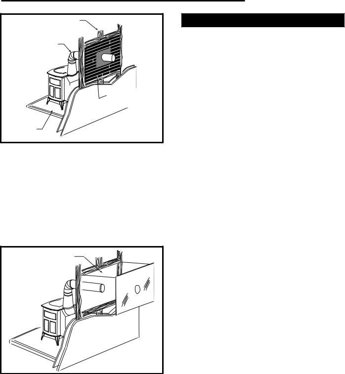
Wall Shields
One way to reduce clearances is with a wall shield constructed of 24 gauge or heavier sheet metal, or of another noncombustible material such as 1/2” (13 mm) insulation board or common brick “laid on flat,” with the 3¹⁄" (90 mm) side down.
Shields must be spaced out from the combustible surface 1" (25 mm) on noncombustible spacers, as in Figure 13. The spacers should not be directly behind the stove or chimney connector.
Air must be able to flow between the wall and the shield. At least 50% of the bottom 1" (25 mm) of the shield should be open and the shield must be open at the top. Use metal screening, as in Figure 14, to keep stray objects from falling behind the shield.
The shield for a top-exit stove must extend 10" (254 mm) above the top of the stove; for a rear exit configuration, the shield must be 36” (914 mm) high. The shield for the chimney connector must be 30” (762 mm) wide, centered behind the pipe; for installations that use an approved prefabricated chimney to pass through the ceiling, the chimney connector shield must stop 1” (25 mm) below the ceiling.
 Air Flow
Metal |
|
|
Screening |
|
|
Wall Shield |
|
|
Stud Wall |
|
|
Framing |
|
|
Noncombustible |
|
|
Spacer and |
Wall |
|
Fasteners |
||
Shield |
||
|
||
|
Metal Lathe or |
|
Drywall |
Noncombustible |
|
|
Spacers |
|
Airflow |
|
|
|
ST248 |
Fig. 14 Approved wall shield construction.
2000956 |
11 |
Encore Woodburning Stove
Chimney Connector Heat Shields
Chimney Connector Heat Shields should be used whenever the rear heat shield is used, or in any other situation when it is necessary to protect nearby combustibles from the heat of the connector. The ceiling above horizontal runs of chimney connector must be protected as well if the clearance is inadequate.
In top-exiting installations, the connector shield must extend to a point exactly 28” (710 mm) above the flue collar or to an elbow in the connector, whichever is less. If the top-exiting connector extends to the ceiling where it connects with a prefabricated insulated metal chimney, an additional ceiling heat shield must be installed that is 24” (610 mm) in diameter and that extends 1” (25 mm) below the ceiling. The ceiling shield must be constructed of 24 gauge or heavier sheet metal, and must be centered on the chimney.
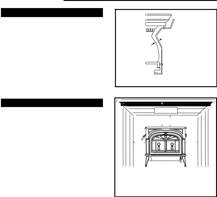
Fireplace and Mantel Trim Shields
A fireplace installation requires special clearance between the side of the stove and the right and left walls, between the side of the stove and the decorative side trim on the fireplace face, and between the top of the stove and the mantel.
Noncombustible shields installed 1” (25 mm) from the combustible surface on noncombustible spacers, called ventilated shields, may be used to reduce clearances.
To protect a mantel from the heat of an Encore in a fireplace installation, use a custom-made ventilated mantel shield that is at least 48” (1219 mm) long, that is centered over the stove. (Fig. 15) Ventilated shields for side trim must extend the full length of the trim.
An unprotected mantel (“A”, Fig. 16) cannot be more than 9” (229 mm) deep and must have a minimum clearance of 39” (990 mm), measured from the stove’s top plate. With a ventilated shield, this clearance may be reduced safely to 18” (457 mm).
Unprotected top trim (B) protruding 9” (229 mm) or less from the face of the fireplace must be a minimum of 39” (990 mm) from the stove’s top surface. With a ventilated trim shield, this clearance may be reduced safely to 18” (457 mm).
Unprotected side trim (C) that protrudes 2” (51 mm) or less from the face of a fireplace must have a minimum clearance of 10” (254 mm), measured from the stove’s top side edge. With a ventilated trim shield, the clearance may be reduced safely to 8” (203 mm). If the trim extends more than 2” (51 mm), it is subject to the requirements for wall clearance.
The charts and sample installations that follow list all the clearances required for the various installation configurations of the Encore.
 1" (25mm)
 1/4" (6mm)
ST501
Fig. 15 A custom formed mantel shield.
AB
C |
C |
ST253b
Fireplace and Mantel Trim Clearances
|
Unprotected |
Protected |
A. Mantel |
39” (990 mm) |
18” (457 mm) |
B. Top Trim |
39” (990 mm) |
18” (457 mm) |
C. Side Trim |
10” (254 mm) |
8” (203 mm |
Fig. 16 Maintain clearances to combustible components of the mantelpiece.
12 |
2000956 |
 Loading...