


Natural Vent Insert
Models: RHE25
RHE32
RHE42
Installation Instructions & Homeowner's Manual
WARNING! IF THE INFORMATION IN THIS MANUAL IS NOT FOLLOWED EXACTLY, A FIRE OR EXPLOSION MAY RESULT CAUSING PROPERTY DAMAGE,PERSONAL INJURY OR LOSS OF LIFE.
FOR YOUR SAFETY
WHAT TO DO IF YOU SMELL GAS:
•Do not try to light any appliance.
•Do not touch any electric switch
•Do not use any phone in your building.
•Immediately call your gas supplier from your neighbours phone. Follow the gas suppliers instructions.
•If you cannot reach your gas supplier call the fire department.
FOR YOUR SAFETY
DO NOT STORE
OR USE GASOLINE OR OTHER FLAMMABLE VAPOURS AND LIQUIDS IN THE VICINITY OF THIS OR ANY OTHER APPLIANCE.
•Installation and service must be performed by a qualified installer, service agency or your gas supplier.
DE
SI
GN
Vermont Castings, Majestic Products
410 Admiral Blvd. • Mississauga, Ontario, Canada L5T 2N6 • 905-670-7777 www.majesticproducts.com • www.vermontcastings.com
CERTIFIED
C
E
R
T
D IFIE
INSTALLER: DO NOT DISCARD THIS MANUAL - Leave For Homeowner
10000836 8/03 Rev.3

Vermont Castings, Majestic Products RHE Natural Vent Insert
Table of Contents
Please read the Installation & Operating Instructions before using this appliance. Thank you and congratulations on your purchase of a Majestic fireplace insert.
IMPORTANT - Read all instructions and warnings carefully before starting installation. Failure to follow these instructions may result in a possible fire hazard and will void the manufacturers' warranty.
Installation Instructions |
|
General Information .......................................................................................................................... |
3 |
Important Curing/Burn Information .................................................................................................... |
3 |
Locating Your Fireplace .................................................................................................................... |
3 |
Insert Applications ............................................................................................................................. |
3 |
Fireplace Dimensions ........................................................................................................................ |
4 |
Mantels .............................................................................................................................................. |
5 |
Framing and Finishing ....................................................................................................................... |
5 |
Combustion Air .................................................................................................................................. |
5 |
Zero Clearance Applications ............................................................................................................ |
6 |
Gas Specifications ............................................................................................................................ |
6 |
Gas Line Installation .......................................................................................................................... |
6 |
Remote Switch for RN / RP Valves ................................................................................................... |
7 |
Venting Instructions ........................................................................................................................... |
8 |
Venting and Installation ..................................................................................................................... |
8 |
Common Flue Installations ................................................................................................................ |
9 |
Liner Installation ................................................................................................................................ |
9 |
Draft Relief Opening .......................................................................................................................... |
9 |
Test Chimney Draw ........................................................................................................................... |
9 |
Vent Safety System ........................................................................................................................... |
9 |
Fan Kit ............................................................................................................................................. |
10 |
Fan Removal Instructions ............................................................................................................... |
10 |
Operating Instructions |
|
General Glass Information ............................................................................................................. |
11 |
Louvre Removal .............................................................................................................................. |
11 |
Glass Cleaning ................................................................................................................................ |
11 |
Glass Frame Removal ..................................................................................................................... |
11 |
Installation of Logs & Burner Lava Rock ......................................................................................... |
11 |
Large Lava Rock Placement ........................................................................................................... |
12 |
Flame Adjustment (RN /RP Models) ............................................................................................... |
12 |
Temperature Adjustment (TN / TP Models) .................................................................................... |
12 |
Flame Characteristics ...................................................................................................................... |
12 |
First Firing ....................................................................................................................................... |
13 |
Lighting & Operating Instructions .................................................................................................... |
14 |
Troubleshooting Gas Control (SIT 820 Gas Valve) ......................................................................... |
15 |
Troubleshooting Gas Control (SIT 630 Gas Valve) ......................................................................... |
16 |
Troubleshooting Gas Control (Honeywell Valve) ........................................................................... |
17 |
Maintenance |
|
Cleaning the Standing Pilot Control System ................................................................................... |
18 |
Brass Cleaning ................................................................................................................................ |
18 |
Replacement Parts .............................................................................................................................................. |
19 |
Optional Accessories |
|
Ceramic Refractory ......................................................................................................................... |
22 |
Zero Clearance Kit .......................................................................................................................... |
22 |
Remote Controls ............................................................................................................................. |
22 |
A Trim Options for RHE25 .............................................................................................................. |
22 |
B Trim Options for RHE32 .............................................................................................................. |
26 |
C Trim Options for RHE42 .............................................................................................................. |
34 |
Warranty .............................................................................................................................................................. |
38 |
2 |
10000836 |
Vermont Castings, Majestic Products RHE Natural Vent Insert
Installation Instructions
This gas appliance should be installed by a qualified installer in accordance with local building codes and with current CSAB149.1 Installation codes for Gas Burning Appliances and Equipment.
For U.S.A Installations follow local codes and/or the current National Fuel Gas Code. ANSI Z223.1.
FOR SAFE INSTALLATION AND OPERATION OF YOUR MAJESTIC GAS FIREPLACE INSERT PLEASE NOTE THE FOLLOWING:
1.This appliance gives off high temperatures and should be located out of high traffic areas and away from furniture and draperies.
2.Children and adults should be alerted to the hazards of the high surface temperatures of this appliance and should stay away to avoid burns or ignition of clothing.
3.Children should be carefully supervised when they are in the same room as your appliance.
4.Under no circumstances should this appliance be modified. Parts removed for servicing should be replaced prior to operating this appliance again.
5.Installation and any repairs to this appliance should be carried out by a qualified service person. A professional service person should be contacted to inspect this appliance annually. Make it a practice to have all of your gas appliances checked annually. More frequent cleaning may be required due to excess lint and dust from carpeting, bedding material, etc.
6.Control compartments, burners and air passages in this appliance should be kept clean and free of dust and lint. Make sure that the gas valve and pilot light are turned off before you attempt to clean this unit.
7.The venting system (chimney) of this appliance should be checked at least once a year and if needed your venting system should be cleaned.
8.Keep the area around your appliance clear of combustible materials, gasoline and other flammable vapor and liquids. This appliance should not be used as a drying rack for clothing, nor should Christmas stockings or decorations be hung in the area of it.
9.Under no circumstances should any solid fuels (wood, coal, paper or cardboard etc.) be used in this appliance.
10.The flow of combustion and ventilation air must not be obstructed in any way.
11.These appliances are certified for installation in a solid fuel burning fireplace unless using the model HEZC Zero Clearance kit. When the Zero Clearance kit is used, and the appliance is installed directly on carpeting, vinyl tile or any combustible material other than wood, the appliance must be installed on a metal or wood panel extending the full width and depth of the appliance.
12.This appliance requires adequate ventilation and combustion air to operate properly.
Proposition 65 Warning: Fuels used in gas, woodburning or oil fired appliances, and the products of combustion of such fuels, contain chemicals known to the State of California to cause cancer, birth defects and other reproductive harm.
California Health & Safety Code Sec. 25249.6
IMPORTANT:
PLEASE REVIEW THE FOLLOWING CAREFULLY
Remove any plastic from trim parts before turning the fireplace ON.
It is normal for fireplaces fabricated of steel to give off some expansion and/or contraction noises during the start up or cool down cycle. Similar noises are found with your furnace heat exchanger or car engine.
It is not unusual for your Majestic gas fireplace to give off some odor the first time it is burned. This is due to the curing of the paint and any undetected oil from the manufacturing process.
Please ensure that your room is well ventilated - open all windows.
It is recommended that you burn your Majestic fireplace for a least six (6) hours the first time you use it. If optional fan kit has been installed, place fan in the "OFF" position during this time.
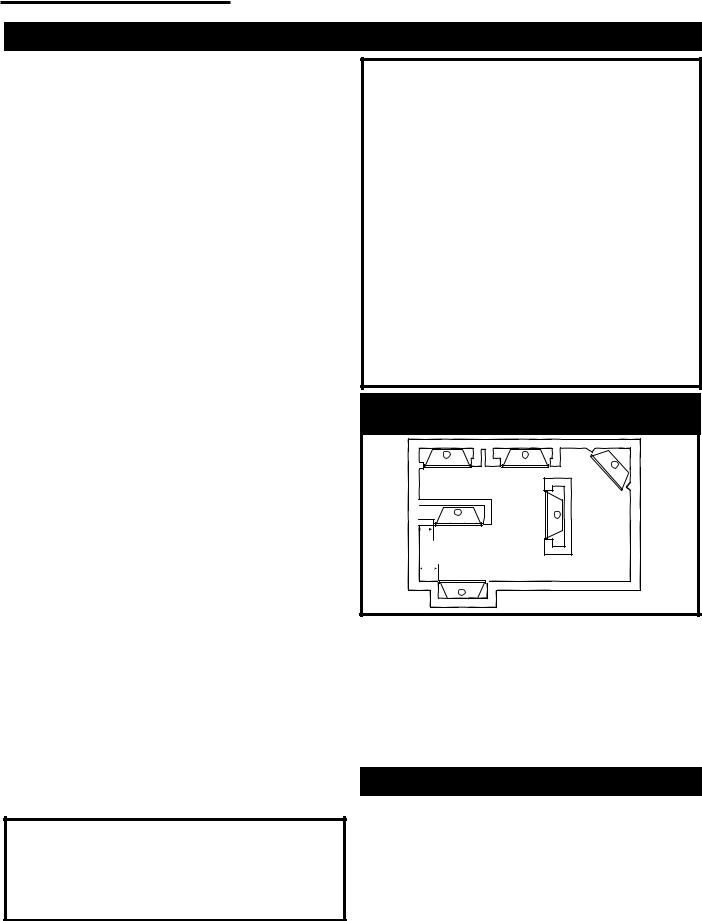
Locating Your Gas Fireplace Insert with Zero Clearance Kit
X E A B
C
X D
X F
FP1249
Fig 1. Locating unit with zero clearance kit.
A) |
Flat on wall |
B) |
Cross corner |
C) |
Island |
D) |
*Room divider |
E) |
*Flat on wall corner |
F) |
Chase installation |
NOTE: (Fig. 1)
* When you install your Majestic fireplace in (D) Room divider or (E) Flat on wall corner positions, a minimum of 6" (X) (153mm) clearance must be maintained from the perpendicular wall and the outer edge of the trim.
Insert Applications
Before installing the gas fireplace insert, consideration must be given to the functioning needs of the fireplace. The size of the fireplace cavity, the design of the chimney for effective venting should be determined. The availability of the gas supply as well as electricity for the insert fan must be confirmed.
10000836 |
3 |
Vermont Castings, Majestic Products RHE Natural Vent Insert
|
|
|
|
|
|
|
|
|
|
|
|
|
|
|
|
|
|
|
|
|
|
|
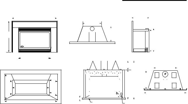
Fireplace Dimensions |
|
|
|
|
|
|
|
|
|
|
|
|
|
|
|
|
|
|
|
|
|
|
|
|
|
|
|
|||||||||||||||||||||||||||||||
|
|
|
|
|
|
|
|
|
|
|
|
|
|
|
|
B |
|
|
|
|
|
|
|
|
|
|
|
|
|
|
|
D |
|
|
|
|
|
|
|
|
|
|
|
|
|
|
|
|
|
|
|
F |
|
|
|
|
|
|
|
|
|
|
|
|
|
|
|
|
|
|
|
|
|
|
|
|
|
|
|||
|
|
|
|
|
|
|
|
|
|
|
|
|
|
|
|
|
|
|
|
|
|
|
|
|
|
|
|
|
|
|
|
|
|
|
|
|
|
|
|
|
|
|
|
|
|||||||||||||||||||||||||||||||||||||
|
|
|
|
|
|
|
|
|
|
|
|
|
|
|
|
|
|
|
|
|
|
|
|
|
|
|
|
|
|
|
|
|
|
|
|
|
|
|
|
|
|
|
|
|
|
|
|
|
|
|
|
|
|
|
|
|
|
|
|
|
|
|
|
|
|
|
|
|
|
|
|
|
|
||||||||
|
|
|
|
|
|
|
|
|
|
|
|
|
|
|
|
|
|
|
|
|
|
|
|
|
|
|
|
|
|
|
|
|
|
|
|
|
|
|
|
||||||||||||||||||||||||||||||||||||||||||
|
|
|
|
|
|
|
|
|
|
|
|
|
|
|
|
|
|
|
|
|
|
|
|
|
|
|
|
|
|
|
|
|
|
|
|
|
|
|
|
|
|
|
|
|
|
|
|
|
|
|
|
|
|
|
|
|
|
|
|
|
|
|
|
|
|
|
|
|
|
|
|
|
|
|
|
|
|
|
|
|
|
|
|
|
|
|
|
|
|
|
|
|
|
|
|
|
|
|
|
|
|
|
|
|
|
|
|
|
|
|
|
|
|
|
|
|
|
|
|
|
|
|
|
|
|
|
|
|
|
|
|
|
|
|
|
|
|
|
|
|
|
|
|
|
|
|
|
|
|
|
|
|
|
|
|
|
|
|
|
||||
|
|
|
|
|
|
|
|
|
|
|
|
|
|
|
|
|
|
|
|
|
|
|
|
|
|
|
|
|
|
|
|
|
|
|
|
|
|
|
|
|
|
|
|
|
|
|
|
|
|
|
|
|
|
|
|
|
|
|
|
|
|
|
|
|
|
|
|
|
|
|
|
|
|
|
|
||||||
|
|
|
|
|
|
|
|
|
|
|
|
|
|
|
|
|
|
|
|
|
|
|
|
|
|
|
|
|
|
|
|
|
|
|
|
|
|
|
|
|
|
|
|
|
|
|
|
|
|
|
|
|
|
|
|
|
|
|
|
|
|
|
|
|
|
|
|
|
|
|
|
|
|
|
|
|
|
|
|
|
|
|
|
|
|
|
A |
|
|
|
|
|
|
|
|
|
|
|
|
|
|
|
|
|
|
|
|
|
|
|
|
|
|
|
|
|
E |
|
|
|
|
|
|
|
|
|
|
|
|
|
|
|
|
|
|
|
|
|
|
|
|
|
|
|
|
|
|
|
|
|
|
|
|
|
|
|
|
|
|||||
|
|
|
|
|
|
|
|
|
|
|
|
|
|
|
|
|
|
|
|
|
|
|
|
|
|
|
|
|
|
|
|
|
|
|
|
|
|
|
|
|
|
|
|
|
|
|
|
|
|
|
|
|
|
|
|
|
|
|
|
|
|
|
|
|
|
|
|
|
|
|
|
|
|
|
|||||||
|
|
|
|
|
|
|
|
|
|
|
|
|
|
|
|
|
|
|
|
|
|
|
|
|
|
|
|
|
|
|
|
|
|
|
|
|
|
|
|
|
|
|
|
|
|
|
|
|
|
|
|
|
|
|
|
|
|
G |
|||||||||||||||||||||||
|
|
|
|
|
|
|
|
|
|
|
|
|
|
|
|
|
|
|
|
|
|
|
|
|
|
|
|
|
|
|
|
|
|
|
|
|
|
|
|
|
|
|
|
|
|
|
|
|
|
|
|
|
|
|
|
|
|
|
|
|
|
|
|
|
|||||||||||||||||
|
|
|
|
|
|
|
|
|
|
|
|
|
|
|
|
|
|
|
|
|
|
|
|
|
|
|
|
|
|
|
|
|
|
|
|
|
|
|
|
|
|
|
|
|
|
|
|
|
|
|
|
|
|
|
|
|
|
|
|
|
|
|
|
|
|||||||||||||||||
|
|
|
|
|
|
|
|
|
|
|
|
|
|
|
|
|
|
|
|
|
|
|
|
|
|
|
|
|
|
|
|
|
|
|
|
|
|
|
|
|
|
|
|
|
|
|
|
|
|
|
|
|
|
|
|
|
|
|
|
|
|
|
H |
|
|
|
|
|
|
|
|
|
|
|
|
|
|
|
|||
|
|
|
|
|
|
|
|
|
|
|
|
|
|
|
|
|
|
|
|
|
|
|
|
|
|
|
|
|
|
|
|
|
|
|
|
|
|
|
|
|
|
|
|
|
|
|
|
|
|
|
|
|
|
|
|
|
|
|
|
|
|
|
|
||||||||||||||||||
|
|
|
|
|
|
|
|
|
|
|
|
|
|
|
|
|
|
|
|
|
|
|
|
|
|
|
|
|
Maintain 1" |
|
|
|
|
|
|
|
|
|
|
|
|
|
|
|
|
|
|
|
|
|
|
|
|
|
|
|
|
|
|
|
|
|
|
|
|
|
|
|
|
|
|||||||||||
|
|
|
|
|
|
|
|
|
|
|
|
|
|
|
|
|
|
|
|
|
|
|
|
|
|
|
|
|
|
|
|
|
|
|
|
|
|
|
|
|
|
|
|
|
|
|
|
|
|
|
|
|
|
|
|
|
|
|
|
|
|
|
|
|
|
|
|
|
|
||||||||||||
|
|
|
|
|
|
|
|
|
|
|
|
|
|
|
|
|
|
|
|
|
|
|
|
|
|
|
|
|
|
|
|
|
|
|
|
|
|
|
|
|
|
|
|
|
|
|
|
|
|
|
|
|
|
|
|
|
|
|
|
|
|
|
|
|
|
|
|
|
|
||||||||||||
|
|
|
|
|
|
|
|
|
|
|
|
|
|
|
|
|
|
|
|
|
|
|
|
|
|
|
|
|
|
Zero Clearance Kit |
|||||||||||||||||||||||||||||||||||||||||||||||||||
|
|
|
|
|
|
|
|
|
|
|
|
|
|
|
|
C |
|
|
|
|
|
|
|
|
|
(25mm) Clearance |
|
|
|
|
|||||||||||||||||||||||||||||||||||||||||||||||||||
|
|
|
|
|
|
|
|
|
|
|
|
|
|
|
|
|
|
|
|
|
|
|
|
|
to B-Vent |
|
|
|
|
|
|
|
|
|
|
|
|
|
|
|
|
|
|
|
|
|
|
|
|
|
|
|
|
|
|
|
|
|
|
|
|
|
|
|
|
|
|||||||||||||||
|
|
|
|
|
|
|
|
|
|
|
|
|
|
|
|
|
|
|
|
|
|
|
|
|
|
|
|
|
|
|
|
|
|
|
|
|
|
|
|
|
|
|
|
|
|
|
|
|
|
|
|
|
|
|
|
|
|
|
|
|
|
|
|||||||||||||||||||
|
|
|
|
|
|
|
|
|
|
|
|
|
|
|
|
|
|
|
|
|
|
|
|
|
|
|
|
|
|
|
|
|
|
|
|
|
|
|
|
|
|
|
|
|
|
|
|
|
|
|
|
|
|
|
|
|
|
|
|
|
|
||||||||||||||||||||
|
|
|
|
|
|
|
|
Minimum Fireplace |
|
|
|
|
|
|
|
|
|
|
|
|
|
|
|
|
|
|
|
|
|
M |
|
|
|
|
|
|
|
|
|
|
|
|
|
|
|
|
|
|
|
|
|
|
|
|
|
|
|
|
|
|
|
||||||||||||||||||||
|
|
|
|
|
|
|
|
|
|
|
|
|
|
|
|
|
|
|
|
|
|
|
|
|
|
|
|
|
|
|
|
|
|
|
|
|
|
|
|
|
|
|
|
|
|
|
|
|
|
|
|
|
|
|
|
|
|
|
|||||||||||||||||||||||
|
|
|
|
|
|
|
|
|
Insert Opening |
|
|
|
|
|
|
|
|
|
|
|
|
|
|
|
|
|
|
|
|
|
|
|
|
|
|
|
|
|
|
|
|
|
|
|
|
|
|
|
|
|
|
|
|
P |
|
|
|
|
|
|
|
||||||||||||||||||||
|
|
|
|
|
|
|
|
|
|
|
|
|
|
|
|
|
|
|
|
|
|
|
|
|
|
|
|
|
|
|
|
|
|
|
|
|
|
|
|
|
|
|
|
|
|
|
|
|
|
|
|
|
|
|
|
|
|
|
|
|
|
|
|
|
|
||||||||||||||||
|
|
|
|
|
|
|
|
|
|
|
|
|
|
|
|
|
|
|
|
|
|
|
|
|
|
|
|
|
|
|
|
|
|
|
|
|
|
|
|
|
|
|
|
|
|
|
|
|
|
|
|
|
|
|
|
|
|
|
|
|
|
|
|
|
|
|
|
|
|
|
|
|
|
|
|
|
|
|
|
|
|
|
|
|
|
|
|
|
|
|
|
|
|
|
|
|
|
|
|
|
|
|
|
|
|
|
|
|
|
|
|
|
|
|
|
|
|
|
|
|
|
|
|
|
|
|
|
|
|
|
|
L |
|
|
|
|
|
|
|
|
|
|
|
|
|
|
|
|
|
|
|
|
|
|
|
|
|
|
|
||||
|
|
|
|
|
|
|
|
|
|
|
|
|
|
|
|
|
|
|
|
|
|
|
|
|
|
|
|
|
|
|
|
|
|
|
|
|
|
|
|
|
|
|
|
|
|
|
|
|
|
|
|
|
|
|
|
|
|
|
|
|
|
|
|
|
|
|
|
|
|
|
|
|
|
|
|
|
|||||
|
|
|
|
|
|
|
|
|
|
|
|
|
|
|
|
|
|
|
|
|
|
|
U |
|
|
|
|
|
|
|
|
|
|
|
|
|
|
|
|
|
|
|
|
|
K |
|
|
|
|
|
|
O |
|
|
|
|
|
|
|
|
|
|
|
|
|||||||||||||||||
|
|
|
|
|
|
|
|
|
|
|
|
|
|
|
|
|
|
|
|
|
|
|
|
|
|
|
|
|
|
|
|
|
|
|
|
|
|
|
|
|
|
|
|
|
|
|
|
|
|||||||||||||||||||||||||||||||||
|
|
|
|
|
|
|
|
|
|
|
|
|
|
|
|
|
|
|
|
|
|
|
|
|
|
|
|
|
|
|
|
|
|
|
|
|
|
|
|
|
|
|
|
|
|
|
|
|
|
|
|
|
|
|
|
|
|
|
|
|
|
|
|
|
|
|
|
|
|
|
|
|
|
|
|
|
|
|
|||
|
|
|
Q |
|
|
|
|
|
|
|
|
|
|
|
|
|
|
|
|
|
|
|
|
|
|
|
|
|
|
|
|
|
|
|
|
|
|
|
|
|
|
|
|
|
|
|
|
|
|
|
|
|
|
|
|
|
|
|
|
|
|
|
|
|
|
|
|
|
|
|
|
|
|
|
|
|
|
|
|
|
|
|
|
V |
|
|
|
|
|
T |
|
|
|
|
|
|
|
|
|
|
1" |
|
|
|
|
|
|
|
|
|
|
|
|
|
|
|
|
|
|
|
|
|
|
|
|
|
|
|
|
|
|
|
|
|
|
|
|
|
|
|
|
|
|
|
N |
|
|
|
|
|
|
||||||||||||
|
|
|
|
|
|
|
|
|
|
|
|
|
|
|
|
|
|
|
|
|
|
|
|
|
|
|
|
|
|
|
|
|
|
|
|
|
|
|
|
|
|
|
|
|
|
|
|
|
|
|
|
|
|
|
|
|
|
|
|
|
|
|
|
|
|
|
|
||||||||||||||
|
|
|
|
|
|
|
|
|
|
|
|
|
|
|
|
|
|
|
|
|
|
|
|
|
|
|
|
|
|
|
|
|
|
|
|
|
|
|
|
|
|
|
|
|
|
|
|
|
|
|
|
|
|
|
|
|
|
|
|
|
|
|
|
|
|
|
|
|
|
|
|
|
|
|
|||||||
|
|
|
|
|
|
|
|
|
|
|
|
|
|
|
|
|
|
|
|
|
|
|
S |
(25mm) |
|
|
|
|
|
|
|
|
|
|
|
|
|
|
|
|
|
|
|
|
|
|
|
|
|
|
|
|
|
|
|
|
|
|
|
|
|
|
|
|
|
|
|||||||||||||||
|
|
|
|
|
|
|
|
|
|
|
|
|
|
|
|
|
|
|
|
|
|
|
|
|
|
|
|
|
|
|
|
|
|
|
|
|
|
|
|
|
|
|
|
|
|
|
|
|
|
|
|
|
|
|
|
|
|
|
|
|
|
|
|
|
|
|
|
|
|
|
|
|
|
|
|
|
|
|
|
|
|
|
|
|
|
|
|
|
|
|
|
|
|
|
|
|
|
|
|
|
|
|
|
|
|
|
|
|
|
|
|
|
|
|
|
|
|
|
|
|
|
|
|
|
|
|
|
|
|
|
|
|
|
|
|
|
|
|
|
|
|
|
|
|
|
|
|
|
|
|
|
|
|
|
|
|
|
|
|
|
|
|
|
|
|
|
|
|
|
|
|
|
|
|
|
|
|
|
|
|
|
|
|
|
|
|
|
|
|
|
|
|
|
|
|
|
|
|
|
|
|
|
|
|
|
|
|
|
|
|
|
|
|
|
|
|
|
|
|
|
|
|
|
|
|
|
|||||||||||||||||||
|
|
|
|
|
|
|
|
|
|
|
|
|
|
|
R |
|
|
|
|
|
|
|
|
|
|
|
|
|
|
|
|
|
|
Air Inlet Channel |
|
|
|
|
|
|
|
|
|
|
|
|
|
|
|
|
|
|
|
|
|
|
|
|
|
|
|
|
|
|
|
|
|
|
|
|
|
||||||||||
|
|
|
|
|
|
|
|
|
|
|
|
|
|
|
|
|
|
|
|
|
|
|
|
|
|
|
|
|
|
|
|
|
|
Gas Inlet Knock-out |
|||||||||||||||||||||||||||||||||||||||||||||||
|
|
|
|
|
|
|
|
|
|
|
|
|
|
|
|
|
|
|
|
|
|
|
|
|
|
|
|
|
|
|
|
|
|
||||||||||||||||||||||||||||||||||||||||||||||||
|
Q - Fireplace Opening Height |
|
|
T - Firebox Width at Insert Depth(s) |
|
|
|
|
|
|
|
1 = SS or SSD Trim |
|
|
|
|
|
|
|
|
|
|
|
|
|
|
|
|
|
|
|
|
|
|
|
|
|
|
|
||||||||||||||||||||||||||||||||||||||||||
|
R - Fireplace Opening Width |
|
|
U - Firebox Depth at Insert Back Height (V) |
2 = SL or SLD Trim |
|
|
|
|
|
|
|
|
|
|
|
|
|
|
|
|
|
|
|
|
|
|
|
|
|
|
|
|||||||||||||||||||||||||||||||||||||||||||||||||
|
S - Depth of Insert |
|
|
|
|
|
|
|
|
|
V - Insert Back Height |
|
|
|
|
|
|
|
|
|
|
|
|
|
|
|
3 = SXL Trim |
|
|
|
|
|
|
|
|
|
|
|
|
|
|
|
|
|
|
|
|
|
|
|
|
|
|
|
|||||||||||||||||||||||||||
|
|
|
|
|
|
|
|
|
|
|
|
|
|
|
|
|
|
|
|
|
|
|
|
|
|
|
|
|
|
|
|
|
|
|
|
|
|
|
|
|
4 = BSL Trim |
|
|
|
|
|
|
|
|
|
|
|
|
|
|
|
|
|
|
|
|
|
|
|
|
|
|
|
|||||||||||||
|
|
|
|
|
|
|
|
|
|
|
|
|
|
|
|
|
|
|
|
|
|
|
|
|
|
|
|
|
|
|
|
|
|
|
|
|
|
|
|
|
5 = BXL Trim |
|
|
|
|
|
|
|
|
|
|
|
|
|
|
|
|
|
|
|
|
|
|
|
|
|
|
|
|||||||||||||
|
|
|
|
|
|
|
|
|
|
|
|
|
|
|
|
|
|
|
RHE25 |
|
|
|
|
|
|
|
RHE32 |
|
|
|
|
|
|
|
|
|
|
|
|
|
|
RHE42 |
|||||||||||||||||||||||||||||||||||||||
|
|
T |
|
|
|
A-1 |
|
|
|
|
|
|
26³⁄ " |
(680mm) |
|
|
|
26³⁄ " |
|
|
(676mm) |
|
|
|
|
|
|
|
|
30³⁄ " |
|
|
|
|
|
(781mm) |
|||||||||||||||||||||||||||||||||||||||||||||
|
|
|
|
B-1 |
|
|
|
|
|
|
38¹⁄ " |
(978mm) |
|
|
|
38³⁄ " |
|
|
(975mm) |
|
|
|
|
|
|
|
|
43¹⁄ " |
|
|
|
(1095mm) |
|||||||||||||||||||||||||||||||||||||||||||||||||
|
|
R |
|
|
|
|
|
|
|
|
|
|
|
|
|
|
|
|
|
|
|
|
|
|
|
|
|
||||||||||||||||||||||||||||||||||||||||||||||||||||||
|
|
|
|
A-2 |
|
|
|
|
|
|
29¹⁄ " |
(743mm) |
29" |
|
|
|
(737mm) |
|
|
|
|
|
|
|
|
33³⁄ " |
|
|
|
|
|
(848mm) |
|||||||||||||||||||||||||||||||||||||||||||||||||
|
|
I |
|
|
|
|
|
|
|
|
|
|
|
|
|
|
|
|
|
|
|
|
|
|
|
|
|||||||||||||||||||||||||||||||||||||||||||||||||||||||
|
|
|
|
B-2 |
|
|
|
|
|
|
43¹⁄ " (1105mm) |
|
|
|
41¹ ⁄ " (1065mm) |
|
|
|
|
48¹⁄ " (1225mm) |
|||||||||||||||||||||||||||||||||||||||||||||||||||||||||||||
|
|
M |
|
|
|
|
|
|
|
|
|
|
|
|
|
|
|
||||||||||||||||||||||||||||||||||||||||||||||||||||||||||||||||
|
|
|
|
A-3 |
|
|
|
|
|
|
|
- |
|
|
- |
|
|
33" |
|
|
|
(838mm) |
|
|
|
|
|
- |
|
|
|
- |
|
|
|
|
|
|
|
|
|
|
|
|
|
|
|||||||||||||||||||||||||||||||||||
|
|
|
|
|
|
|
|
|
|
|
|
|
|
|
|
|
|
|
|
|
|
|
|
|
|
|
|
|
|
|
|
|
|
|
|
|
|
|
|
|
|
||||||||||||||||||||||||||||||||||||||||
|
|
|
|
|
|
B-3 |
|
|
|
|
|
|
|
- |
|
|
- |
|
|
44" |
|
|
|
(1118mm) |
|
- |
|
|
|
- |
|
|
|
|
|
|
|
|
|
|
|
|
|
|
|||||||||||||||||||||||||||||||||||||
|
|
|
|
|
|
A-4 |
|
|
|
|
|
|
|
- |
|
|
- |
|
|
28" |
|
|
|
(712mm) |
|
|
|
|
|
- |
|
|
|
- |
|
|
|
|
|
|
|
|
|
|
|
|
|
|
|||||||||||||||||||||||||||||||||
|
|
|
|
|
|
B-4 |
|
|
|
|
|
|
|
- |
|
|
- |
|
|
|
|
|
40 ⁄ " (1041mm) |
|
- |
|
|
|
- |
|
|
|
|
|
|
|
|
|
|
|
|
|
|
||||||||||||||||||||||||||||||||||||||
|
|
|
|
|
|
A-5 |
|
|
|
|
|
|
|
- |
|
|
- |
|
|
|
|
|
30¹⁄ " |
|
|
(775mm) |
|
|
|
|
|
- |
|
|
|
- |
|
|
|
|
|
|
|
|
|
|
|
|
|
|
|||||||||||||||||||||||||||||||
|
|
|
|
|
|
B-5 |
|
|
|
|
|
|
|
- |
|
|
- |
|
|
46" |
|
|
|
(1171mm) |
|
- |
|
|
|
- |
|
|
|
|
|
|
|
|
|
|
|
|
|
|
|||||||||||||||||||||||||||||||||||||
|
|
F |
|
|
|
C |
|
|
|
|
|
|
25¹⁄ " |
(641mm) |
|
|
|
28³⁄ " |
|
|
(730mm) |
|
|
|
|
|
31" |
|
|
|
|
|
(787mm) |
||||||||||||||||||||||||||||||||||||||||||||||||
|
|
|
|
D |
|
|
17" |
|
|
(432mm) |
|
|
|
17¹⁄ " |
|
|
(438mm) |
|
|
|
|
|
|
|
|
20¹⁄ " |
|
|
|
|
|
(511mm) |
|||||||||||||||||||||||||||||||||||||||||||||||||
|
|
I |
|
|
|
|
|
|
|
|
|
|
|
|
|
|
|
|
|
|
|
|
|
|
|
||||||||||||||||||||||||||||||||||||||||||||||||||||||||
|
|
|
|
E |
|
|
|
|
|
|
13³⁄ " |
(349mm) |
|
|
|
15 ⁄ " |
|
|
(397mm) |
|
|
|
|
|
|
|
|
17³⁄ " |
|
|
|
|
|
(451mm) |
|||||||||||||||||||||||||||||||||||||||||||||||
|
|
R |
|
|
|
|
|
|
|
|
|
|
|
|
|
|
|
|
|
|
|
|
|
|
|
|
|
|
|||||||||||||||||||||||||||||||||||||||||||||||||||||
|
|
|
|
F |
|
|
15" |
|
|
(381mm) |
|
|
|
17¹⁄ " |
|
|
(435mm) |
|
|
|
|
|
21" |
|
|
|
|
|
(533m) |
||||||||||||||||||||||||||||||||||||||||||||||||||||
|
|
E |
|
|
|
|
|
|
|
|
|
|
|
|
|
|
|
|
|
|
|
|
|||||||||||||||||||||||||||||||||||||||||||||||||||||||||||
|
|
P |
|
|
G |
|
|
|
|
|
|
19¹⁄ " |
(489mm) |
|
|
|
20¹⁄ " |
|
|
(521mm) |
|
|
|
|
|
|
|
|
23¹⁄ " |
|
|
|
|
|
(590mm) |
||||||||||||||||||||||||||||||||||||||||||||||
|
|
L |
|
|
H |
|
|
|
|
|
|
17¹⁄ " |
(445mm) |
20" |
|
|
|
(508mm) |
|
|
|
|
|
|
|
|
22³⁄ " |
|
|
|
|
|
(578mm) |
||||||||||||||||||||||||||||||||||||||||||||||||
|
|
A |
|
|
K |
|
35" |
|
|
(889mm) |
35" |
|
|
|
(889mm) |
|
|
|
|
|
|
|
|
39¹⁄ " (1000mm) |
|||||||||||||||||||||||||||||||||||||||||||||||||||||||||
|
|
C |
|
|
L |
|
|
|
|
|
|
26 ⁄ " |
(676mm) |
|
|
|
26 ⁄ " |
|
|
(676mm) |
|
|
|
|
|
|
|
|
31¹⁄ " |
|
|
|
|
|
(790mm) |
||||||||||||||||||||||||||||||||||||||||||||||
|
|
E |
|
|
M |
|
|
|
|
|
|
8¹⁄ " |
(216mm) |
|
|
|
8¹⁄ " |
|
|
(216mm) |
|
|
|
|
|
|
|
|
8¹⁄ " |
|
|
|
|
|
(216mm) |
||||||||||||||||||||||||||||||||||||||||||||||
|
|
|
|
|
|
|
|
|
|
|
|
|
|
|
|
|
|
|
|
|
|
|
|
|
|
|
|
|
|
||||||||||||||||||||||||||||||||||||||||||||||||||||
|
|
|
|
|
|
N |
|
|
|
|
|
|
37¹⁄ " |
(952mm) |
|
|
|
37¹⁄ " |
|
|
(952mm) |
|
|
|
|
|
|
|
|
37¹⁄ " |
|
|
|
|
|
(954mm) |
|||||||||||||||||||||||||||||||||||||||||||||
|
|
|
|
|
|
O |
|
|
|
|
|
|
19¹⁄ " |
(486mm) |
|
|
|
19¹⁄ " |
|
|
(486mm) |
|
|
|
|
|
|
|
|
21³⁄ " |
|
|
|
|
|
(553mm) |
|||||||||||||||||||||||||||||||||||||||||||||
|
|
|
|
|
|
P |
|
|
|
|
|
|
27¹⁄ " |
(692mm) |
|
|
|
27¹⁄ " |
|
|
(692mm) |
|
|
|
|
|
|
|
|
25³⁄ " |
|
|
|
|
|
(654mm) |
|||||||||||||||||||||||||||||||||||||||||||||
|
M O |
|
|
|
Q |
|
|
|
|
|
|
17³⁄ " |
(451mm) |
21" |
|
|
|
(533mm) |
|
|
|
|
|
|
|
|
23¹⁄ " |
|
|
|
|
|
(591mm) |
||||||||||||||||||||||||||||||||||||||||||||||||
|
I |
P |
|
|
R |
|
25" |
|
|
(635mm) |
28" |
|
|
|
(711mm) |
|
|
|
|
|
29" |
|
|
|
|
|
737mm) |
||||||||||||||||||||||||||||||||||||||||||||||||||||||
|
N |
E |
|
|
S |
|
|
|
|
|
|
13³⁄ " |
(349mm) |
16" |
|
|
|
(407mm) |
|
|
|
|
|
18" |
|
|
|
|
|
(457mm) |
|||||||||||||||||||||||||||||||||||||||||||||||||||
|
I |
N |
|
|
|
|
|
|
|
|
|
|
|
|
|
|
|
|
|
|
|
|
|
|
|||||||||||||||||||||||||||||||||||||||||||||||||||||||||
|
|
|
T |
|
|
|
|
|
|
17¹⁄ " |
(445mm) |
|
|
|
17³⁄ " |
|
|
(451mm) |
|
|
|
|
|
|
|
|
20 ⁄ " |
|
|
|
|
|
(524mm) |
||||||||||||||||||||||||||||||||||||||||||||||||
|
M |
I |
|
|
|
|
|
|
|
|
|
|
|
|
|
|
|
|
|
|
|
|
|
|
|
|
|
|
|
||||||||||||||||||||||||||||||||||||||||||||||||||||
|
|
|
U |
|
|
14" |
|
|
(356mm) |
|
|
|
16¹⁄ " |
|
|
(419mm) |
|
|
|
|
|
21" |
|
|
|
|
|
(533mm) |
|||||||||||||||||||||||||||||||||||||||||||||||||||||
|
U N |
|
|
|
|
|
|
|
|
|
|
|
|
|
|
|
|
|
|
|
|
|
|||||||||||||||||||||||||||||||||||||||||||||||||||||||||||
|
|
|
V |
|
|
|
|
|
|
17³⁄ " |
(451mm) |
|
|
|
20¹⁄ " |
|
|
(514mm) |
|
|
|
|
|
23" |
|
|
|
|
|
(584mm) |
|||||||||||||||||||||||||||||||||||||||||||||||||||
|
M G |
|
|
|
|
|
|
|
|
|
|
|
|
|
|
|
|
|
|
|
|
|
|
|
|||||||||||||||||||||||||||||||||||||||||||||||||||||||||
4 |
10000836 |
Vermont Castings, Majestic Products RHE Natural Vent Insert
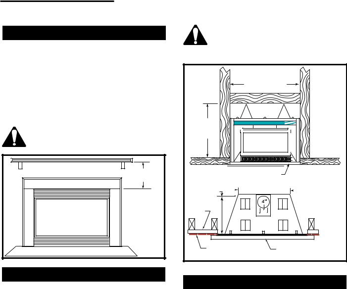
Mantels
When the insert is being installed into a woodburning fireplace the minimum the mantel can be above the fireplace is governed by local building codes applicable to woodburning fireplaces. Consult local authorities having jurisdiction for these clearances.
For applications requiring the use of a Zero Clearance Kit, the minimum a mantel can protrude above the fireplace is 24" (610mm) from the top of the upper louvres. The maximum mantel depth is 8" (200mm). (Fig. 2)
The underside of the mantel will get quite warm. Use only finishes which are heat resistant and do not discolour.
24" Min. |
(610mm) |
FP1325 |
Fig. 2 Minimum mantel height above fireplace.
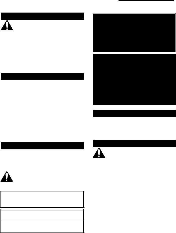
Framing & Finishing
For Zero Clearance Kit applications it is important to determine the finished facing material before beginning to frame. This will allow for the thickness of the finishing material between the frame and the fireplace trim.
Similarily, consideration must be given to the 1" (25mm) depth of the air inlet channel sitting on the fireplace base. Finishing material for the hearth should be flush with the top of the air inlet channel.
If the fireplace is installed at floor level a noncombustible hearth must extend a minimum 12" (305mm) in front of the fireplace.
If the fireplace is recessed into the wall and at least 12" (305mm) above floor level, no hearth is required.
A (3" for RHE25, 4" for RHE32 and RHE42) diameter Class "B" vent must be used when installing the fireplace insert along with the Zero Clearance Kit. The vent system must be a minimum height of 12' (3.7m).
The use of wallpaper adjacent to this fireplace is not recommended, as the high heat given off by this fireplace may adversely effect the binders in the adhesive used to apply the wallpaper.
|
37¹⁄ " (946mm) |
|
35" |
|
|
(889mm) |
|
|
19¹⁄ " (486mm) |
Air Inlet Channel |
|
(RHE25/32) |
27¹⁄ " (692mm) (RHE25/32) |
|
21³⁄ " (553mm) |
||
25³⁄ " (654mm) (RHE42) |
||
(RHE42) |
||
|
||
Dry |
|
|
Wall |
|
|
Finish Wall |
Decorative Trim Kit |
|
|
FP1351a |
|
Fig. 3 RHE insert framing dimensions. |
||
Combustion Air
It is very important that an adequate air supply is available when the unit is being operated. Since most homes of today are tightly sealed and insulated, additional make-up air is usually necessary.
This fireplace has been designed to operate by drawing air in from the front and outer perimeters of the fireplace. The air provides combustion air ensuring a clean burning flame, dilution air for proper venting, as well as, the air which the fan circulates over the firebox/heat exchanger system.
Insulating around the fireplace will result in overheating and possible malfunctioning of the circulating fan.
10000836 |
5 |
Vermont Castings, Majestic Products RHE Natural Vent Insert
Zero Clearance Applications
An alternate air supply is recommended with this component.
For installations other than in existing woodburning fireplaces such as new construction or renovation projects, a Zero Clearance Kit must be used. The kit enables these inserts to be installed in combustible environments. It is recommended that an Air Kit (AKZC) be installed whenever using a Zero Clearance Kit. Consideration must be given to the dimensions of the Zero Clearance Kit and the requirements of the Air Kit when planning the installation.
Gas Specifications
|
|
|
Max. |
Min. |
|
|
|
Input |
Input |
Model |
Fuel |
Gas Control |
Btu/h |
Btu/h |
RHE25RN |
Natural Gas |
Millivolt HI/LO |
22,000 |
15,400 |
RHE25RP |
Propane Gas |
Millivolt HI/LO |
22,000 |
16,500 |
RHE25MN |
Natural Gas |
Manual HI/LO |
22,000 |
15,400 |
RHE25MP |
Propane Gas |
Manual HI/LO |
22,000 |
16,500 |
RHE3RN |
Natural Gas |
Millivolt HI/LO |
30,000 |
21,000 |
RHE32RP |
Propane Gas |
Millivolt HI/LO |
30,000 |
22,500 |
RHE32TN |
Natural Gas |
Thermostat HI/LO |
30,000 |
21,000 |
RHE32TP |
Propane Gas |
Thermostat HI/LO |
30,000 |
22,500 |
RHE42RN |
Natural Gas |
Millivolt HI/LO |
40,000 |
28,000 |
RHE42RP |
Propane Gas |
Millivolt HI/LO |
37,000 |
27,750 |
RHE42TN |
Natural Gas |
Thermostat HI/LO |
40,000 |
28,000 |
RHE42TP |
Propane Gas |
Thermostat HI/LO |
37,000 |
27,750 |
Gas Inlet & Manifold Pressures
|
Natural |
LP |
Minimum Inlet Pressure |
5.5" W.C. |
11.0" W.C. |
Maximum Inlet Pressure |
14.0" W.C. |
14.0" W.C. |
Manifold Pressure |
3.5" W.C. |
10.0" W.C. |
|
|
|
Do not use this appliance if any part of it has been under water. Immediately call a qualified service technician to inspect the unit and replace any part of the control which has been under water.
These gas inserts are approved for installation in solid fuel burning masonry or zero clearance fireplaces.
RHE25 / RHE32 / RHE42
Certified To
ANSI Z 21.88-2002 / CSA 2.33-2002
Vented Gas Fireplace Heaters
The installation of your Majestic Fireplace must conform with local codes, or in the absence of local codes, with National Fuel Gas Code, ANSI Z223.1 latest edition, or CSAB149.1 Installation Code. (EXCEPTION: Do not derate this appliance for elevations up to 4,500 ft (1,370m). Maintain the manifold pressure at 3.5" w.c. for Natural Gas and 10.0" w.c. for LP gas.)
High Elevations
Input ratings are shown in BTU per hour and are certified without deration for elevations up to 4,500 feet (1,370m) above sea level.
For elevations above 4,500 feet (1,370m) in USA, installations must be in accordance with the current ANSI Z223.1 and/or local codes having jurisdiction.
In Canada, please consult provincial and/or local authorities having jurisdiction for installations at elevations above 4,500 feet (1,370m).
Preparation
Before beginning, remove the glass frame from the fireplace. Also check to make sure there is no hidden damage to the fireplace. Take a minute and plan out the gas, vent and electrical supply. Refer to Glass Frame Removal section.
Gas Line Installation
When purging the gas line, the front glass must be removed.
The gas pipeline can be brought into the fireplace base from the right side. It is most convenient to install it from the right side into the gas fittings provided.
When using copper or flex connector use only approved fittings. Always provide a union when using black iron pipe so that gas line can be easily disconnected for burner or fan servicing. Refer to gas specifications for pressure details and ratings.
The gas line connection can be made of either properly tinned 3/8" copper pipe, 3/8" rigid pipe or an approved flex connector.
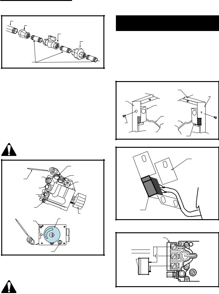
The gas control inlet is 3/8" N.P.T. therefore the 1/2" rigid gas line must be reduced to 3/8" N.P.T. Typical installation layout for rigid pipe is shown following. (Fig. 4)
6 |
10000836 |
Vermont Castings, Majestic Products RHE Natural Vent Insert
|
1/2" Gas Supply |
|
1/2" x 3/8" Reducer |
|
3/8" x 3/8" Shut Off |
|
Valve |
|
3/8" Union |
|
3/8" Nipple |
|
FP1278 |
Fig. 4 |
Typical gas supply installation. |
During any pressure testing of the gas line system, when the test pressures are to exceed 1/2 psi (3.5 kpa) the fireplace and its gas valve must not be connected to that system.
At test pressures equal to or less than 1/2 psi, the gas valve of the fireplace may be connected to the gas line, but must be in the closed position.
Some municipalities have additional local codes, it is always best to consult the local authority and the CSAB149.1 installation code in Canada.
FOR U.S.A Installations consult the current National Fuel Gas Code, ANSI Z223.1
Always check for gas leaks with a mild soap and water solution. Do not use an open flame for leak testing.
|
|
|
Manifold Gas |
|
|
|
|
Outlet |
|
Thermostat |
Brass |
Brass Plug |
||
Plug |
||||
Bulb |
|
|
||
|
|
Pressure |
||
|
|
|
||
|
Gas Inlet |
Regulator |
||
|
|
|||
Thermocouple Inlet |
|
|||
Pilot Tube Entry |
|
|
||
|
Pilot |
|
Control Knob |
|
|
Adjustment |
Control Knob |
||
|
Screw |
|
||
|
|
|
||
|
|
|
HI |
|
|
|
it |
OFF |
|
|
|
LO |
PILOT |
|
|
Minimum Rate Screw |
|||
|
(Nonadjustable) |
HV118 |
||
Fig. 5 On fireplaces equipped with the Eurosit 630 gas valves, there are brass plugs in two of the holes. These plugs are not to be removed. The gas inlet hole has a plastic cap in it. Remove the plastic cap and connect your gas supply line at this point.
The MN/MP valve control used on the RHE25 does not include the thermostat bullb as shown in Figure 5.
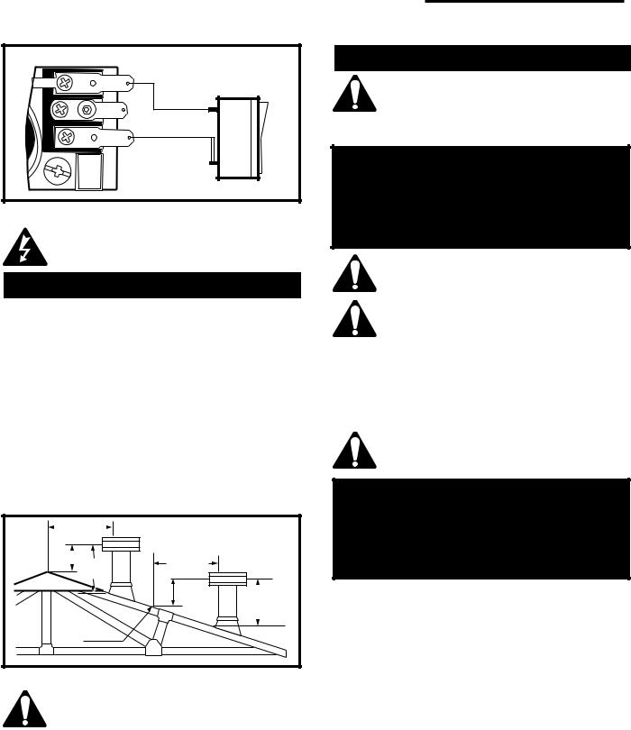
Installation of Remote Switch
for RN/RP Gas Valves
1.Thread wire through gas inlet opening on the right side of fireplace. Do not cut wire or insulation on metal edges.
2.Slide switch assembly from the back, between subframe and trim, then fasten the screw. (Fig. 6)
3.For left side installation reverse switch position in bracket and repeat Step 2. (Fig. 7)
4.Connect wiring to gas valve (Fig. 8a & b) and switch.
Right Side Installation |
Left Side Installation |
|
|
Trim Top |
Trim Left |
|
|
|
Trim Right |
|
Side |
|
|
|
Side |
|
|
ON/OFF Switch |
|
|
Assembly |
|
|
|
Wiring from |
|
Trim |
Millivolt Gas |
Trim |
Valve |
Screw |
|
Screw |
|
|
ON/OFF Switch Assembly |
FP1253 |
|
|
|
|
Fig. 6 Slide switch assembly between subframe and trim.
Bracket Switch
ON/OFF
Switch
FP1254
Fig. 7 For left side installation, reverse switch position in bracket.
Valve
Thermopile

TH TP THTP
|
P |
I |
|
TOL |
|
FP382a
Fig. 8a ON/OFF switch or millivolt thermostat.
10000836 |
7 |
Vermont Castings, Majestic Products RHE Natural Vent Insert
|
TH |
|
TP |
|
TPTH |
|
FP1218a |
Fig. 8b |
ON/OFF switch wiring. |
If a remote wall switch is required for this fireplace installation, do not wire wall switch to 120V power supply.
Venting Instructions
Canadian Installations:
The venting system must be installed in accordance with the current CSA-B149.1 installation code, and the authority having jurisdiction.
U.S.A. Installations:
The venting system must be installed in accordance with the current National Fuel Gas Code, ANSI Z223.1.
Minimum clearances to combustible materials is 1" (25mm) for B Vent (use of single wall vent is not allowed).
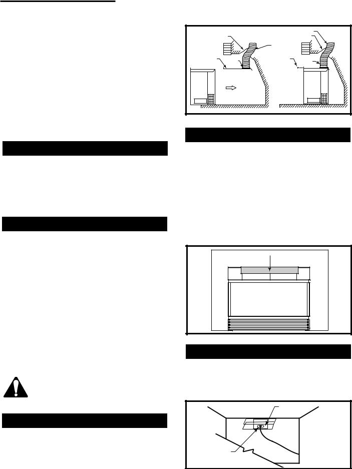
As with any natural draft appliances, the vent cap must always extend a minimum of 2' (610mm) above any structure within a 10' (3m) horizontal plane. (Fig. 9)
|
0 To 10’ |
|
|
|
2’ Min. |
0 To 10’ |
|
|
3’ |
|
|
|
Min. |
(3m) |
|
|
|
2’ |
3’ |
|
|
(610mm) |
|
|
|
Min. |
(914mm) |
|
|
|
Min. |
|
Reference |
|
|
|
Point |
|
|
|
|
|
AC246a |
Fig. 9 |
Example of the 2', 3', 10' rule. |
|
|
A minimum 12' (3.7m) vent height is required to effectively vent this fireplace.
Venting and Installation
Installer must attach red warning plate with screws supplied with the gas fireplace insert to the inside of the firebox of the fireplace into which the gas fireplace insert is installed.
WARNING
This fireplace has been converted for use with gas only and cannot be used for burning wood or solid fuels unless all original parts have been replaced and the fireplace has been re-approved by the authority having jurisdiction.
Cutting any sheet metal parts of the fireplace, in which the gas fireplace insert is to be installed, is prohibited.
If the factory-built fireplace has no gas access hole(s) provided, an access hole of 1¹⁄" (37.5mm) or less may be drilled through the lower sides or bottom of the firebox in a proper workmanship like manner. This access hole must be plugged with a noncombustible insulation after the gas supply line has been installed.
Ensure there are no obstructions to side air passages of decorative trim once installed on insert.
WARNING
Some factory built fireplaces have air passages on face of fireplace for zero clearance capabilities. All trim kits are designed so as to allow airflow to these passages. Under no circumstances should these passages be blocked.
1.The Majestic gas inserts are designed for recessed installations into solid fuel Masonry or Factory Built Noncombustible fireplaces that have been installed in accordance with the National, Provincial, State and local building codes.
2.Measure for minimum fireplace opening requirement on Page 4 of this installation manual. (If firebrick
[refractory] is removed from a factory built fireplace in order to gain minimum gas fireplace insert opening requirements, a minimum of 1/4" (6.4mm) air space is required between the gas insert fireplace's outer casing and the inner wall of the factory built fireplace).
3.To assure top performance, safety and efficiency, all inserts must be installed with an approved 4" diameter flue liner, with exception of RHE25, which should be installed with an approved 3" liner,as per CSA-B.149 or National Fuel Code ANSI Z223.
8 |
10000836 |
Vermont Castings, Majestic Products RHE Natural Vent Insert
4.Flue damper must be fully blocked in the open position or removed for installation.
5.The chimney must be clean and in good working order and constructed of noncombustible materials.
6.Make sure that all chimney cleanouts fit properly so air cannot leak into the chimney.
7.Glass door, screen kits and log grate may be removed for installation of insert into factory built fireplace.
8.Install the insert without the trim frame and make all gas, venting and electrical connections.
9.Install decorative trim frame. Please refer to Frame Assembly and Mounting instructions on this manual.
Common Flue Installations
In some areas it is possible to vent more than one gas fireplace into the same flue. You must ensure the flue being shared has the proper capacity to handle both fireplaces. Check installation codes for venting capacity information.
As always it is best to check with the authority having jurisdiction prior to commencement of the installation.
Liner Installation
Insert liner from top of chimney through the damper opening and attach to 3" flue collar (for RHE25); 4" flue collar (for RHE32 & RHE42). For best results use three (3) sheet metal screws and a hose clamp.
For natural draft inserts packing fibreglass insulation around the liner in the damper area will isolate the fireplace cavity from the chimney and prevent drafts and noises during operation.
In case the fireplace opening is only minimum height (17¹⁄ " for RHE25) (20" for RHE32) (22³⁄ " for RHE42) and access from the front is not possible, remove the flue collar plate - unscrew and slide out from the back of the unit. Now attach the liner to the flue collar, lift up and simply slide flue collar plate back onto the unit top. It is important the plate is completely inserted and the front screw is fastened again in order to line up the flue outlet and the liner properly. (Fig. 10)
If fireplace lintel is wider than 8" (205mm), the height of the fireplace opening must be 25" (635mm) to allow for a 90° offset elbow to be installed.
Draft Relief Opening
This insert is equipped with a draft-relief opening which receives its dilution air supply through the opening behind the louvres. These openings must not be obstructed or altered in any way. (Fig. 11)
|
Damper |
Chimney Liner |
||
|
|
Damper |
||
|
|
|
Chimney |
|
Flue |
|
|
Liner |
|
|
|
|
|
|
Collar Plate |
Clamp |
Screw |
Clamp |
|
|
|
|
|
FP1354 |
Fig. 10 |
Remove flue collar plate and attach to flue collar. |
|||
Test Chimney Draw
A "Chimney Draw" test must be made before the installation is complete.
1.Close all doors and windows in the home and start exhaust fans in the kitchen and bathroom.
2.Light unit and operate for 5 minutes.
3.Hold an ignited match or cigarette in front of the unit. Refer to Figure 11 for the location of the draft hood opening.
4.Check to make sure smoke from the match or cigarette is drawn into the fireplace. If it is not, turn the unit off and check for causes creating the lack of adequate draft.
Test for Draft at This Location
FP1371
Fig. 11 Hold an ignited match in front of fireplace.
Vent Safety System
These inserts are equipped with a vent safety shut down switch. This switch is factory installed, wired and tested. Check and make sure the switch and wires are in the proper position. The safety switch is heat activated and wired in series with the pilot system. (Fig. 12)
Bracket
Vent Safety
Switch
FP1372
Fig. 12 Vent safety switch.
10000836 |
9 |
Vermont Castings, Majestic Products RHE Natural Vent Insert
Operation of this fireplace when not connected to a properly installed and maintained venting system or tampering with the vent safety shutoff system can result in carbon monoxide (CO) poisoning and possibly death.
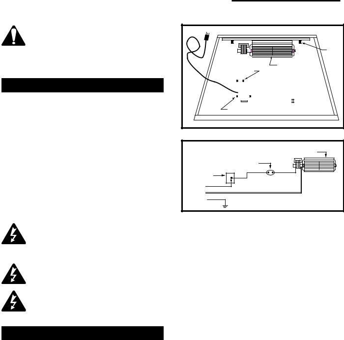
Fan Kit
115 Volt, 60 Hz. 56W
The fan kit includes the following: fan, temperature sensor, speed control and a 6 ft. cord. The following explains how to start and set the fan for automatic operation.
1.Plug in the electrical cord.
2.Start gas fire - see lighting procedures.
3.Turn on fan speed control.
4.Wait until the unit has warmed up sufficiently to activate the temperature sensor.
5.Once fan starts, adjust speed control to desired fan speed. The fan will now automatically come on every time the fireplace is in operation. Should the fan not be needed simply turn off the speed control.
Stud
Thermal Sensor is |
Fan is installed |
||||||||||||
attached to burner |
|||||||||||||
at the back of |
|||||||||||||
base |
|||||||||||||
the air intake |
|||||||||||||
|
|
|
|
|
|
|
|||||||
|
|
|
|
|
|
|
box |
||||||
|
|
|
|
|
|
|
|||||||
|
|
|
Stud |
|
|
|
|
|
|
||||
|
|
|
Valve |
|
|||||||||
|
|
|
|
|
|
|
|
|
|||||
|
|
|
|
|
|
|
|||||||
|
|
|
|
|
|
|
|
|
|
|
|
|
|
Fan Speed Control/Junction Box
|
FP1252 |
Fig. 13 |
Fan location. |
|
Fan |
|
Temperature Sensor |
Speed |
|
Control |
|
Black |
|
White |
|
Ground |
|
|
FP394 |
Fig. 14 |
Wiring diagram RN/RP. |
The appliance, when installed must be electrically connected and grounded in accordance with local codes or, in the absence of local codes, with the current CSA C22.1 Canadian Electrical Code.
For U.S.A. installations, follow local codes and the national electrical code, ANSI/NFPA No. 70.
Should this fan require servicing, the power supply must be disconnected. For rewiring of any replacement components refer to Figures 13 & 14.
Fan Removal Instructions
1.Turn off gas and electricity.
2.Remove the front glass.
3.Remove the logs.
4.Remove burner assembly and rear log support plate.
5.Remove the fan mounting nuts (2). (Fig. 13)
6.Slip off the electrical connector at the motor.
7.Lift out the fan.
8.To reinstall, reverse procedure.
10 |
10000836 |
Vermont Castings, Majestic Products RHE Natural Vent Insert
Operating Instructions
General Glass Information
Only ceramic glass approved for use in Majestic fireplaces may be used for replacement on this fireplace.
1.The use of substitute glass will void all product warranties.
2.Care must be taken to avoid breakage of the glass.
3.Under no circumstances should this fireplace be operated without front glass properly installed, or with any cracked or broken glass. Replacement of any glass assembly as supplied by the manufacturer should be done by a licensed qualified service person.
Louvre Removal
To remove top flat louvre pull louvre up and then lift out.
2.
Louvre
1.
Glass
Panel
FP444
Fig. 15 Louvre removal.
Glass Cleaning
It will be necessary to clean the glass periodically. During start-up, condensation, which is normal, forms on the inside of the glass and causes lint, dust and other airborne particles to cling to the glass surface. Also initial paint curing may deposit a slight film on the glass. It is therefore recommended the glass be cleaned two or three times with a non-ammonia household cleaner and warm water (we recommend gas fireplace glass cleaner). After that the glass should be cleaned two or three times during each heating season depending on the circumstances present.
Clean glass after first two weeks of operation.
Glass Frame Removal
1.Remove the top louvre. (Refer to "Louvre Removal" section)
2.Open the access door.
3.Remove two (2) machine screws from the bottom of glass frame. (Fig. 16)
4.Lift up and unhook glass frame at the top.
Before remounting glass frame, brass trim must be installed. Refer to instructions in "Frame Mounting" section.
Glass Frame |
|
Screws |
|
Machine Screws |
|
Open Access Door |
FP1373 |
|
Fig. 16 Remove glass frame.
Installation of Logs
1 . Remove front glass. (Refer to "Glass Removal" section)
2.Remove logs from packaging.
3.Place rear log (JR4/KR4 or SR4) on rear bracket (ensure log is seated properly, leveled and centered to the unit), so it will not move from side to side and is firmly positioned on the bracket.
4.Slip front ember log (KR1or SR1) down in the front deflector.
5.Place front left log (JR2/KR2 or SR2) on top burner, left side. Use log's bottom holes to locate it into the left bracket log locator studs.
6.Place front right log (JR3/KR3 or SR3) on top of burner, right side. Use log's bottom holes to locate it into the right bracket log locator studs.
7.Place burner lava rock material on top of burner. (Refer to Figs. 17, 18 & 19 for proper location).
8.Place top left log (JR5/KR5 or SR5) onto locator notches. Ensure log is secure.
9.Place top right log (JR6/KR6 or SR6) onto locator notches. Ensure log is secure.
Top logs must be placed properly into notches.
10000836 |
11 |
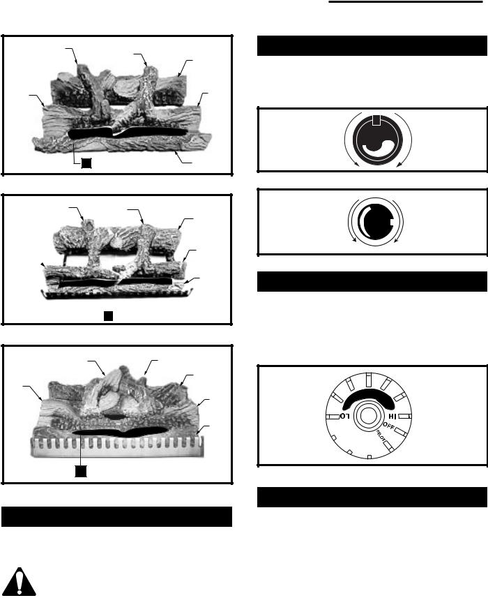
Vermont Castings, Majestic Products RHE Natural Vent Insert
JR5
JR6
JR4
JR2 |
JR3 |
LG279 |
|
Burner Lava Rock |
KR1 |
|
Placement |
|
|
|
|
|
Fig. 17 RHE25 log and lava rock placement.
KR5 |
KR6 |
|
KR4 |
KR3
KR2 
|
KR1 |
Burner Lava Rock |
LG280 |
Placement |
Fig. 18 RHE32 log and lava rock placement.
SR5 |
SR6 |
|
SR4 |
SR2 |
|
|
SR3 |
|
SR1 |
Burner Lava Rock |
|
Placement |
LG281 |
Fig. 19 RHE42 log and lava rock placement.
Large Lava Rock Placement
The large lava rock provided with this fireplace must be placed on the firebox base on either side of the burner assembly.
Under no circumstances should these lava rock be placed on top of the burner assembly.
Flame Adjustment (RN/RP Models)
For fireplaces equipped with HI/LO valve, flame adjustment is accomplished by rotating the HI/LO adjustment knob located near the center of the gas control.
(Figs. 20 & 21)
Turn |
|
|
|
counterclockwise |
LO |
HI |
Turn clockwise |
to decrease |
|
to increase |
|
|
|
||
flame height |
|
|
flame height |
Fig. 20 Flame adjustment knob for Honeywell Valve.
Turn |
IH |
Turn clockwise |
|
counterclockwise |
|
||
|
to decrease |
||
to increase |
|
||
|
flame height |
||
flame height |
LO |
||
|
|||
|
|
Fig. 21 Flame adjustment knob for SIT Valve.
Temperature Adjustment (TN/TP Models)
The HI/LO reference on the control knob (Fig. 22) is to indicate a higher or lower temperature setting. This setting controls the heat by reducing then shutting off the flame after the desired temperature is reached. Position the control knob where it effectively maintains a comfortable room temperature.
Fig. 22 Temperature adjustment knob for TN/TP models.
Flame Characteristics
It is important to periodically perform a visual check of the pilot and the burner flames. Compare them to Figure 23 and Figure 24 or 25. If any of the flames appear abnormal, call a service person.
12 |
10000836 |
 Loading...