

Page 1

Wireless
DSL Gateway
GT704WGB
User Manual
Page 2

Contents
Wireless DSL Gateway User Manual
1
Introduction
1.0 Introduction
1.1 System Requirements
1.2 Features
1.3 Important Safety Instructions
1.4 Getting to Know the Gateway
2
Performing a Quick Setup
2.0 Introduction
2.1 Accessing Quick Setup Screens
2.2 Changing the Password
3
Viewing the Gateway’s Status
3.0 Introduction
3.1 Broadband Connection Status
3.2 Network Status
4
Configuring Wireless Settings
4.0 Introduction
4.1 Accessing the Wireless Setup
4.2 Basic Wireless Setup
4.3 Wireless Advanced Settings
4.4 Wireless Status
4.5 WPS (WiFi Protected Setup)
Page 3

Contents
Wireless DSL Gateway User Manual (con’t)
5
Configuring Advanced Settings
5.0 Introduction
5.1 Accessing Advanced Settings
5.2 DSL Settings
5.3 DHCP Settings
5.4 LAN IP Address
5.5 WAN IP Address
5.6 QoS Settings
5.7 Remote Management
5.8 Dynamic Routing
5.9 Static Routing
5.10 UPnP (Universal Plug and Play)
5.11 USB Port Detection
5.12 Time Zone
5.13 Remote Syslog Capture
6
Configuring Security Settings
6.0 Introduction
6.1 Accessing Wired Security Settings
6.2 Firewall
6.3 Applications
6.4 Rule Management
6.5 DMZ Hosting
6.6 NAT (Network Address Translation)
6.7 Port Mapping
7
Parental Controls
7.0 Introduction
7.1 Activating Parental Controls
7.2 Services Blocking
7.3 Website Blocking
7.4 Schedule Rules
Page 4

Contents
Wireless DSL Gateway User Manual (con’t)
8
Configuring Utilities
8.0 Introduction
8.1 Accessing Utilities
8.2 Restore Default Settings
8.3 Upgrade Firmware
8.4 Multiple PVC
8.5 Web Activity Log
8.6 System Log
8.7 OAM Ping Test
8.8 Ping Test
8.9 Reboot
9
Troubleshooting
9.0 Introduction
9.1 Troubleshooting
9.2 Frequently Asked Questions
A
Reference
A.0 Introduction
A.1 Locationg Computer Information
A.2 Locating Windows Operating System Files
B
Setting Up Static IP
B.0 Introduction
B.1 Windows 98 SE
B.2 Windows Me
B.3 Windows 2000
B.4 Windows XP
Page 5

Contents
Wireless DSL Gateway User Manual (con’t)
C
Computer Security
C.0 Introduction
C.1 Overview
C.2 Comparing DSL Service with a Dial-Up Modem
C.3 Gateway Security
C.4 Computer Security
C.5 Electronic Security
D
Specifications
D.0 Introduction
D.1 General
D.2 Wireless Operating Range
D.3 LED Indicators
D.4 Environmental
E
Glossary
E.0 Introduction
E.1 Glossary
F
Service Acronyms
F.0 Introduction
F.1 Service Acronym Definitions
Page 6

1.0 Introduction
1.1 System Requirements
1.2 Features
1.3 Important Safety
Instructions
1.4 Getting to Know the
Gateway
1
Introduction
5
© 2008 Verizon. All Rights Reserved.
Page 7

The Gateway is the simplest way to
connect computers to a high-speed
broadband connection. This easy-to-use
product is perfect for the home office or
small business. If you want to take your
computing to the next level, the Wireless
DSL Gateway is sure to be one of the keys
to your success.
© 2008 Verizon. All Rights Reserved.
6
Page 8

Wireless DSL Gateway User Manual
10/16/08
1.1 System Requirements
The Gateway must be used with the following systems and software:
Active s DSL service
Computer with an s 10 Mbps or 10/100 Mbps Ethernet connection, or USB
connection
Microsoft Windows 98 Second Edition (SE), Millennium Edition (Me), NT 4.0, s
2000, XP, Vista Mac OS 7.1+, 8.0+, 9.0+, OS X+
Note: USB LAN port is not supported with Microsoft Windows NT 4.0, Windows
Vista 64-bit, or Mac OS.
Internet Explorer 4.0 or higher (5.x+ recommended) or Netscape Navigator s
4.0 or higher (4.7+ recommended)
TCP/IP network protocol installed on each computers
1.2 Features
The Gateway features:
Plug-and-Play installation support for computers running Windows operating s
systems (98SE, Me, 2000, XP, and Vista)
ADSL WAN port (RJ-11) s
Full-rate ANSI T1.413 Issue 2, ITU G.992.1(G.dmt) and G.992.2(G.lite) s
standard compliance
Auto-handshake for different ADSL flavorss
USB 1.1 device specification compliances
12 Mbps USB data rate (full speed) supports
Bridged Ethernet over ATM, PPP over ATM, PPP over Ethernets
Precise ATM traffic shaping s
IP packet routing and transparent bridges
7
© 2008 Verizon. All Rights Reserved.
Page 9

Introduction
1
1.3 Important Safety Instructions
RIP-1, RIP-2, and static routing protocol supports
Built-in NAT, DHCP servers
DNS relay supports
PAP/CHAP authentication, administrative passwords through Telnets
64-, 128-, and 256-bit WEP/WPA wireless LAN securitys
IEEE 802.3 Ethernet standard compliances
10/100 Base-T Ethernet ports (4)s
Fast Ethernet flow control supports
Web-based configuration setups
FTP firmware upgradeables
Web download supports
802.11b/g supports
WPS supports
1.3 Important Safety Instructions
When using telephone equipment, basic safety precautions should always be
followed to reduce the risk of fire, electrical shock, and personal injury, including
the following:
Do not use this product near water – for example, near a bathtub, kitchen s
sink, laundry tub, or swimming pool, or in a wet basement;
Avoid using a telephone (other than a cordless type) during an electrical s
storm, as there may be a remote risk of electrical shock due to lightning;
Do not use the telephone to report a gas leak in the vicinity of the leak;s
Use only the power cord and batteries indicated in this manual;s
Do not dispose of batteries in fire, as they may explode – check with local s
codes for possible special disposal instructions.
8
© 2008 Verizon. All Rights Reserved.
Page 10
Wireless DSL Gateway User Manual
10/16/08
1.3a Telephone Line Cord Caution
To reduce the risk of fire, use only No. 26 AWG or larger (e.g., 24 AWG) UL Listed
or CSA Certified Telecommunication Line Cord.
1.4 Getting to Know the Gateway
This section contains a quick description of the Gateway’s lights, ports, etc.
The Gateway has several indicator lights (LEDs) and a button on its front panel,
and a series of ports and switches on its rear panel.
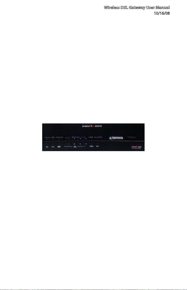
1.4a Front Panel
The front panel of the Gateway features nine lights: Power, DSL, Internet,
Ethernet (4), USB, and Wireless.
Power Light
The Power light displays the Gateway’s current status. If the Power light glows
steadily green, the Gateway is receiving power and fully operational. When the
Power light is rapidly flashing, the Gateway is initializing. If the Power light is
glows red when the Power cord is plugged in, the Gateway has suffered a critical
error and technical support should be contacted.
DSL Light
The DSL light illuminates when the Gateway is connected to a DSL line.
9
© 2008 Verizon. All Rights Reserved.
Page 11

Introduction
1
1.4 Getting to Know the Gateway
Internet Light
When the Internet light glows steadily, the Gateway is connected to the DSL
provider. When it flashes, the Gateway’s built-in DSL modem is training for the
DSL service.
Ethernet Lights
The Ethernet lights illuminate when the Gateway is connected to one or more of
its yellow Ethernet ports.
USB Light
The USB light illuminates when the Gateway is connected via its USB port.
Wireless Light
The Wireless light illuminates when the Gateway is connected wirelessly (if the
Gateway’s Wireless feature is turned on).
WPS Button
The WPS button activates WPS (WiFi Protected Setup) on the Gateway. See
chapter 4, “Configuring Wireless Settings,” for more information about WPS.
10
© 2008 Verizon. All Rights Reserved.
Page 12
Wireless DSL Gateway User Manual
10/16/08
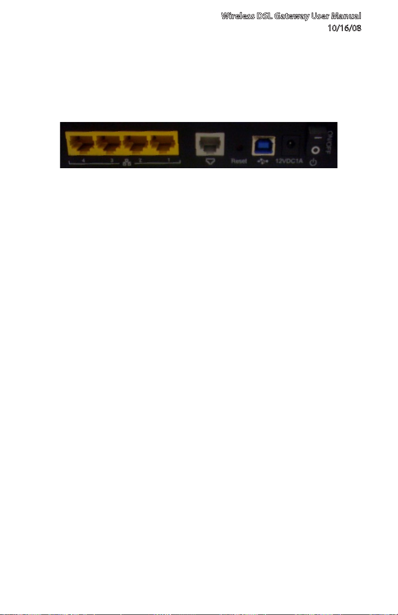
1.4b Rear Panel
The rear panel of the Gateway contains seven ports (Ethernet [4], Phone, USB,
and Power), as well as Reset and Power switches.
Ethernet Ports
The Ethernet ports are used to connect computers to the Gateway via Ethernet
cable. The Ethernet ports are 10/100 Mbps auto-sensing ports, and either a straightthrough or crossover Ethernet cable can be used when connecting to the ports.
DSL Port
The DSL port is used to connect the Gateway to a DSL (Digital Subcriber Line)
connection.
Reset Switch
Depressing the Reset switch for one second will restore the Gateway’s factory
default settings. To reset the Gateway, depress and hold the Reset switch for
approximately ten seconds. The reset process will start after releasing the switch.
USB Port
The USB port is used to connect a computer to the Gateway via USB cable.
11
© 2008 Verizon. All Rights Reserved.
Page 13

Introduction
1
1.4 Getting to Know the Gateway
Power Port
The Power port is used to connect the Power cord to the Gateway.
Warning: Do not unplug the Power cord from the Gateway during the reset
process. Doing so may result in permanent damage to the Gateway.
Power Switch
The Power switch is used to power the Gateway on and off.
© 2008 Verizon. All Rights Reserved.
12
Page 14
2.0 Introduction
2.1 Accessing Quick Setup
Screens
2.2 Changing the Password
2
Performing a
Quick Setup
13
© 2008 Verizon. All Rights Reserved.
Page 15

This chapter is a guide through a quick
set up of the Gateway, including how
to connect the Gateway to the ISP and
changing the Gateway’s password.
© 2008 Verizon. All Rights Reserved.
14
Page 16
Wireless DSL Gateway User Manual
10/16/08
2.1 Accessing Quick Setup Screens
To complete the quick setup, have the Welcome Letter or ISP Worksheet handy. If
the document is not available, contact the ISP immediately.
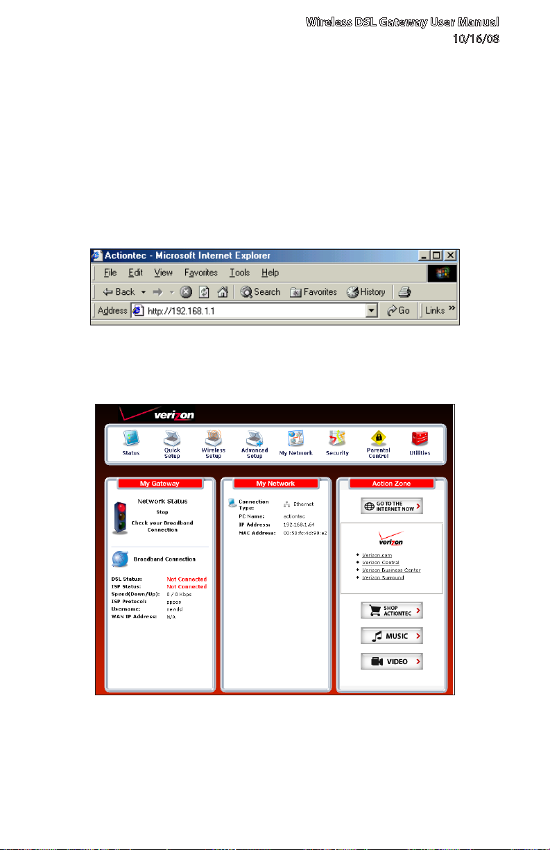
To access the Quick Setup screens:
Open a Web browser. In the “Address” text box, type: 1.
http://192.168.1.1
then press Enter on the keyboard.
The “Home” screen appears. Click 2. Quick Setup.
15
© 2008 Verizon. All Rights Reserved.
Page 17
Quick Setup
2
2.1 Accessing Quick Setup Screens
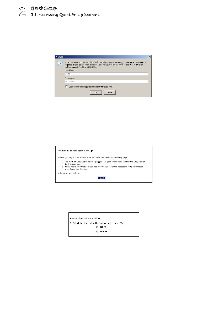
A login window appears. Enter the user name and password in the 3.
appropriate text boxes, then click OK.
Note: The default user name is “admin.” The default password is “password.”
Follow the instructions in the “Welcome to the Quick Setup” screen, then 4.
click Next.
At the top of the next window, select 5. PPPoE or DHCP.
© 2008 Verizon. All Rights Reserved.
16
Page 18
Wireless DSL Gateway User Manual
10/16/08
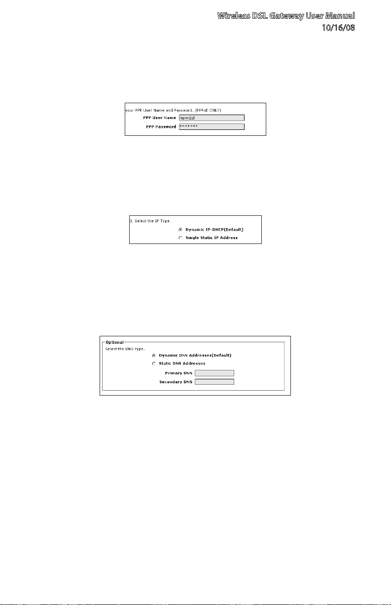
If PPPoE was selected in step 5, the default user name and password are 6.
entered in the appropriate text boxes.If “DHCP” was selected, go to step 8.
If PPPoE was selected in step 5, select the IP type (“Dynamic IP-DHCP 7.
[Default]” or “Single Static IP Address”). If Single Static IP Address was
selected, enter the address in the appropriate text box.
Optional8. - Select the DNS type (“Dynamic DNS Addresses [Default]” or
“Static DNS Addresses”). If Static DNS Addresses was selected, enter the
primary and secondary DNS addresses in the appropriate text boxes. If
unsure what to enter in this section, contact the ISP.
Click 9. Apply at the bottom of the screen.
17
© 2008 Verizon. All Rights Reserved.
Page 19
Quick Setup
2
2.2 Changing the Password
Read the instructions on the next screen. The Gateway is successfully 10.
configured.
The Power light flashes rapidly while the Gateway restarts, then glows steadily
green when fully operational. The Internet light will also glow steadily green. The
Gateway is now configured and users can start surfing the Internet.
If an error appears, stating the Web browser was unable to connect to the
Internet, check the configuration settings. Ensure all the information required by
the ISP is entered correctly.
2.2 Changing the Password
To create or change the password allowing access to the Gateway’s Web
Configuration screens, follow these instructions:
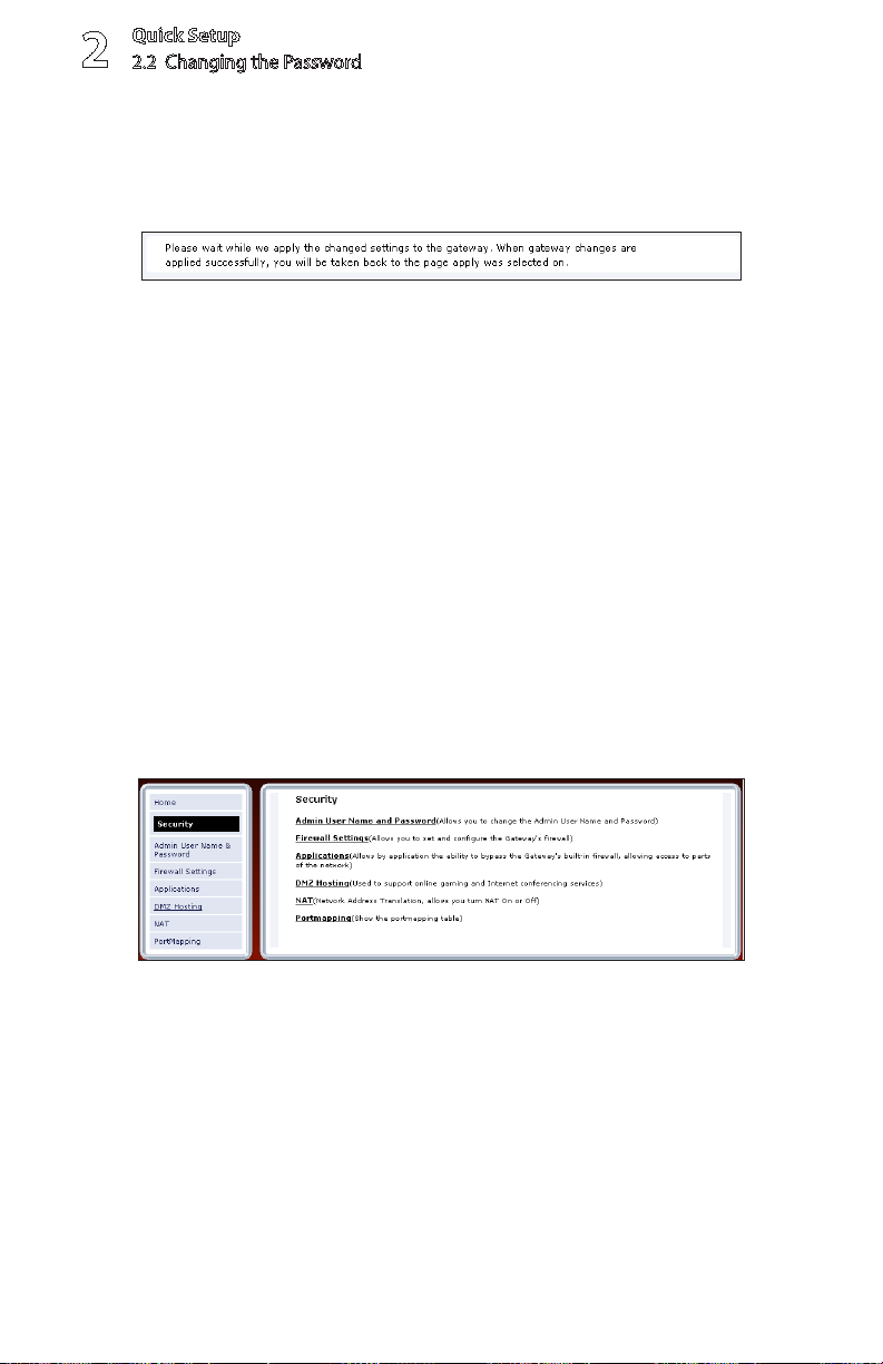
From the “Home” screen, select 1. Security.
The “Security” screen appears. Select 2. Admin User Name and Password.
© 2008 Verizon. All Rights Reserved.
18
Page 20
Wireless DSL Gateway User Manual
10/16/08
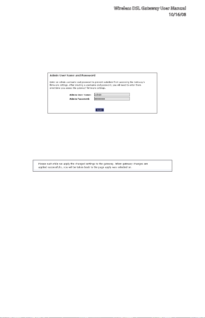
The “Change Admin Username/Password” screen appears. Enter a new 3.
Username in the “Admin User Name” text boxt, then enter a new password in
the “Admin Password” text box. Make sure to write down the user name and
password and keep it in a secure location. They will be needed to access the
Gateway’s Web Configuration screens in the future.
Click 4. Apply at the bottom of the screen.
Read the instructions on the next screen. The user name and password are 5.
successfully changed.
Once the Gateway has rebooted, the new user name and password are active.
To access the Gateway’s Web Configuration screens, the new user name and
password must be entered.
19
© 2008 Verizon. All Rights Reserved.
Page 21
3.0 Introduction
3.1 Broadband Connection
Status
3.2 Network Status
3
Viewing the
Gateway’s
Status
© 2008 Verizon. All Rights Reserved.
20
Page 22
After configuring the Gateway, the
Gateway’s connection and network status
can be viewed. The Internet connection
status is viewed in the “Broadband
Connection Status” screen, while the
network status is viewed in the “My
Network” screen.
21
© 2008 Verizon. All Rights Reserved.
Page 23
Viewing Status
3
3.1 Broadband Connection Status
3.1 Broadband Connection Status
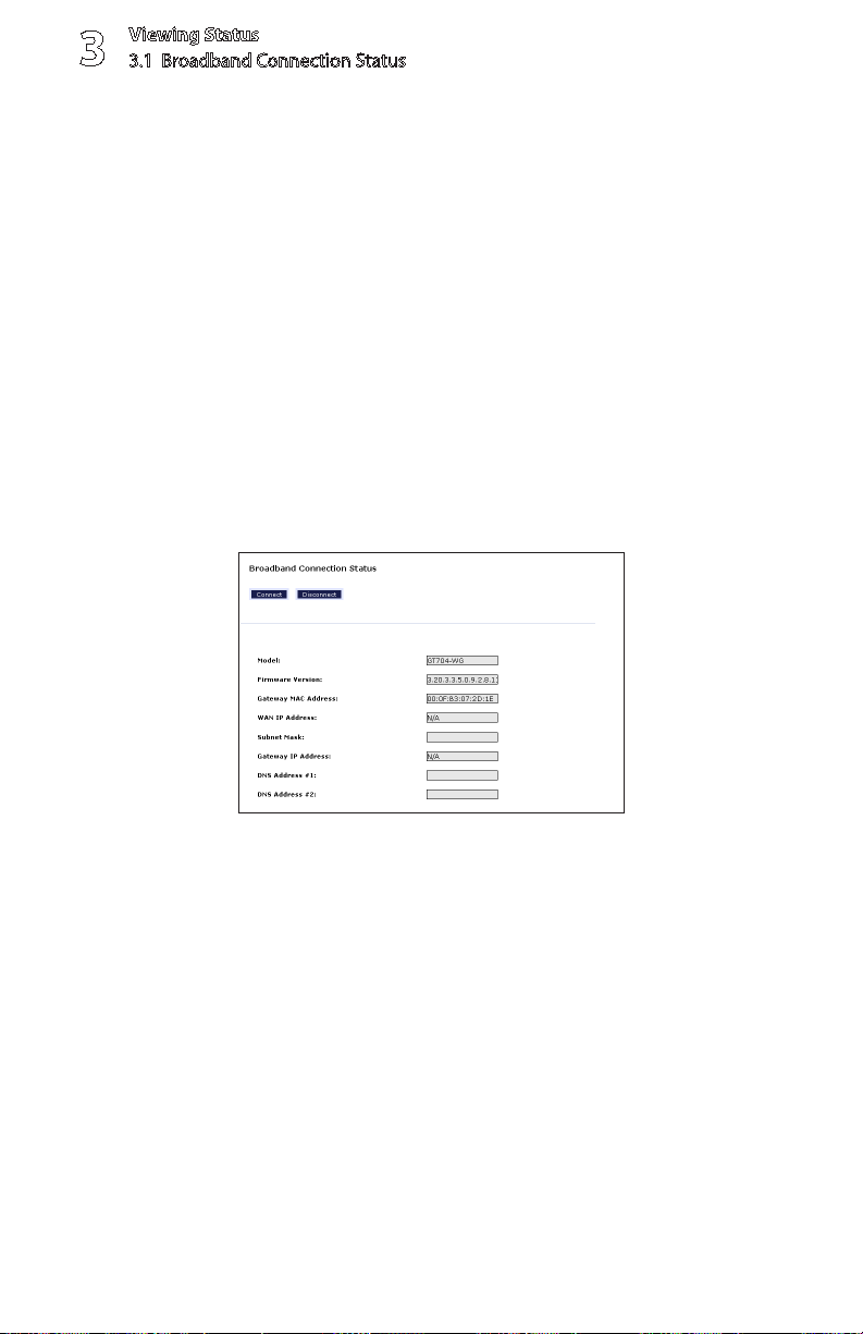
To view the Gateway’s connection statistics, select Status in the Home screen.
The “Broadband Connection Status” screen appears. There are three sections in
this screen: General Statistics, PPP Status, and DSL Status.
Note: No settings (other than connecting or disconnecting from the Internet
by clicking on Connect or Disconnect) can be changed from the Broadband
Connection Status screen.
3.1a General Statistics
The top section of the Broadband Connection Status screen displays general
statistics regarding the Gateway, including model number, firmware version, IP
address, and gateway IP address.
© 2008 Verizon. All Rights Reserved.
22
Page 24
Wireless DSL Gateway User Manual
10/16/08
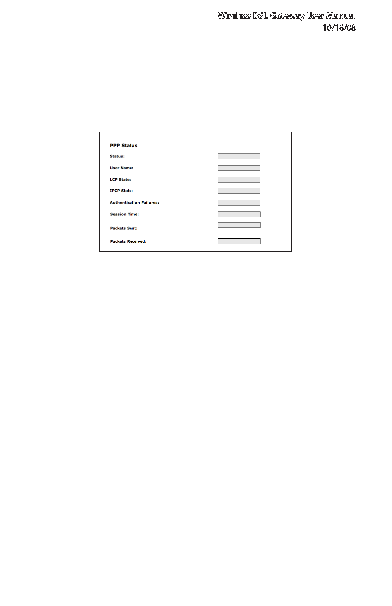
3.1b PPP Status
The middle section of the Broadband Connection Status screen displays the
status of the Gateway’s PPP connection, including user name, authentication
failures, and packets sent and received.
23
© 2008 Verizon. All Rights Reserved.
Page 25

Viewing Status
3
3.1 Broadband Connection Status
3.1c DSL Status
The bottom section of the Broadband Connection Status screen displays the
status of the Gateway’s DSL connection, including mode settings, connection
status, and number of discarded packets. Click Reset to refresh all statistics on
this screen
In the menu on the left side of the Broadband Connection Status screen, there
are two other options available to view: NAT Table and Routing Table. Click to
generate the option of choice.
24
© 2008 Verizon. All Rights Reserved.
Page 26
Wireless DSL Gateway User Manual
10/16/08
NAT Table
Selecting NAT Table generates the “NAT Table” screen. This screen displays an
overview of the current list of open connections through NAT (Network Address
Translation) the Gateway supports between the networked computers and the
Internet.
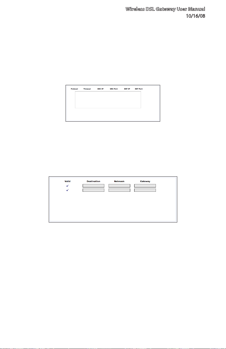
Routing Table
Selecting Routing Table generates the “Routing Table” screen. This screen
displays the an overview of the Gateway’s network routes.
25
© 2008 Verizon. All Rights Reserved.
Page 27

Viewing Status
3
3.2 Network Status
3.2 Network Status
To view the Gateway’s network status, select My Network in the “Home” screen.
The “My Network” screen appears, listing all devices connected to the network.
From this screen, various settings can be accessed, including Website blocking,
Schedule Rules, and Enable Application.
To view the network status of a particular device, click View Device Details for
the device. An overview of the device’s network status appears.
26
© 2008 Verizon. All Rights Reserved.
Page 28
4.0 Introduction
4.1 Accessing Wireless Setup
4.2 Basic Wireless Setup
4.3 Wireless Advanced Settings
4.4 Wireless Status
4.5 WPS (WiFi Protected Setup)
4
Configuring
Wireless
Settings
27
© 2008 Verizon. All Rights Reserved.
Page 29
This chapter explains how to set up the
Gateway’s wireless network capabilities,
including creating a wireless network,
enabling wireless security, and viewing the
Gateway’s wireless connection status.
© 2008 Verizon. All Rights Reserved.
28
Page 30
4.1 Accessing Wireless Setup
To access the Gateway’s Wireless Settings:
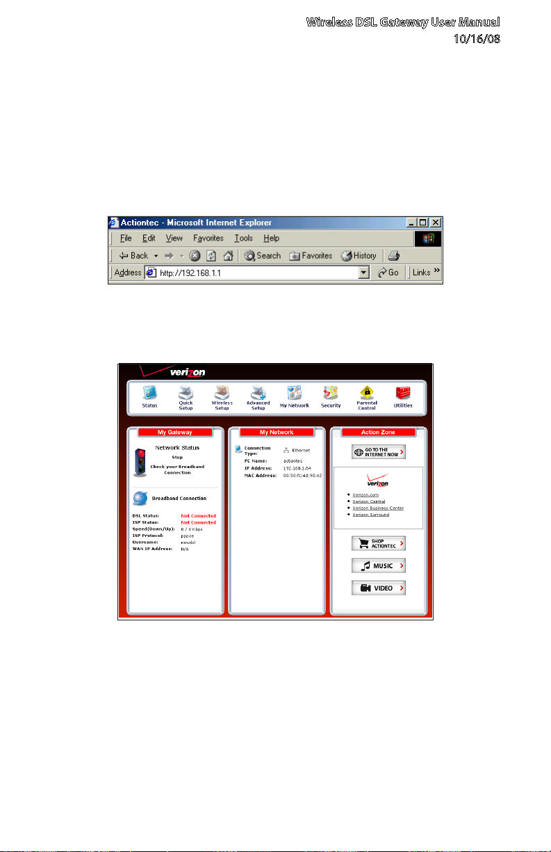
Open a Web browser. In the “Address” text box, type: 1.
http://192.168.1.1
then press Enter on the keyboard.
The “Home” screen appears. Click2. Wireless Setup.
Wireless DSL Gateway User Manual
10/16/08
29
© 2008 Verizon. All Rights Reserved.
Page 31

Wireless Settings
4
4.1 Accessing Wireless Setup
A login window appears. Enter the user name and password in the 3.
appropriate text boxes, then click OK.
Note: The default user name is “admin.” The default password is “password.”
© 2008 Verizon. All Rights Reserved.
30
Page 32

Wireless DSL Gateway User Manual
10/16/08
The “Wireless Basic Settings” screen appears. To modify a specific 4.
configuration, click on its name in the menu bar on the left, or from the list in
the middle of the screen.
31
© 2008 Verizon. All Rights Reserved.
Page 33

Wireless Settings
4
4.2 Basic Wireless Setup
4.2 Basic Wireless Setup
To perform a basic setup of a wireless network using the Gateway:
In the “Wireless Basic Settings” screen, turn the Gateway’s wireless radio on 1.
by selecting On.
Create a name for the wireless network and enter it in the “ESSID” text box.2.
Select a channel from the “Channel” drop-down menu. In the United States, 3.
use channels 1-11.
Activate WEP (Wired Equivalent Privacy) to secure the wireless network by 4.
selecting WEP.
Create a 64-bit WEP key by selecting 64-bit WEP Key from the “select a WEP 5.
Key” drop-down menu, then entering a 10-digit key in the “Key Code” text
box. The digits can be any letter from A-F, and any number from 0-9.
Write down the Gateway’s wireless settings. To connect other devices to the 6.
wireless network, the devices’ wireless settings must match the Gateway’s
wireless settings exactly. Check the “Current Wireless Status” box (available
in any wireless setting screen) to view the Gateway’s wireless status and
settings.
© 2008 Verizon. All Rights Reserved.
32
Page 34

Wireless DSL Gateway User Manual
10/16/08
4.3 Wireless Advanced Settings
To access the Gateway’s wireless advanced settings screens, select Advanced
Settings from the menu on the left side of the “Wireless Basic Settings” screen.
This generates the “Wireless Advanced Settings” screen. In this screen, the
security of the wireless network can be activated and fortified.
4.3a Wireless Security
The first section of the Wireless Advanced Settings screen involves wireless
security (securing wireless traffic as it transmits through the air). The Gateway
offers three types of wireless security: WEP, WEP+802.1x, and WPA.
33
© 2008 Verizon. All Rights Reserved.
Page 35

Wireless Settings
4
4.3 Wireless Advanced Settings
WEP
Selecting WEP in the Wireless Advanced Settings screen generates the “WEP
Key” screen. Here, the authentication type, encryption level, and WEP keys are
entered to activate WEP (Wired Equivalent Privacy) security encryption for the
wireless network.
Authentication Type - There are three authentication types: Open, Shared,
and Both. Open authenticaton allows any wireless-enabled device to recognize
the network, even if the WEP key is invalid. Shared allows only wireless-enabled
devices with the correct WEP key to recognize the network.
64-bit WEP - 64-bit WEP requires one or more keys, each key comprising five
hexadecimal pairs. One key (Key 1) is automatically generated by the Gateway
at startup, based on the Gateway’s MAC address. This key is also displayed on
a sticker on the bottom of the Gateway. A hexadecimal digit consists of an
alphanumeric character ranging from 0-9 or A-F. An example of a 64-bit WEP key
is: 4E-A3-3D-68-72. To create a new set of 64-bit WEP keys, activate one or more
keys by clicking in the appropriate circles, then enter five hexadecimal digit pairs
in each activated Key text box (Key 1-, Key 2-, Key 3-, Key 4-). After activating
64-bit WEP, a computer with wireless capability can join the network only if
these same keys are entered in the computer’s wireless encryption scheme.
128-bit WEP - 128-bit WEP requires one or more keys, each key comprising 13
hexadecimal pairs. A hexadecimal digit consists of an alphanumeric character
ranging from 0-9 or A-F. An example of a 128-bit WEP key is: 3D-44-FE-6C-A1-EF2E-D3-C4-21-74-5D-B1. To create a 128-bit WEP key, activate Key 1 by clicking in
the appropriate circle, select “128 bit” from the drop-down list on the right, then
enter 13 hexadecimal digit pairs in the Key text box. After activating 128-bit
WEP, a computer with wireless capability can join the network only if this key is
entered in the computer’s wireless encryption scheme.
34
© 2008 Verizon. All Rights Reserved.
Page 36

Wireless DSL Gateway User Manual
10/16/08
256-bit WEP - 256-bit WEP requires one or more keys, each key comprising 29
hexadecimal pairs. A hexadecimal digit consists of an alphanumeric character
ranging from 0-9 or A-F. To create a 256-bit WEP key, activate Key 1 by clicking
in the appropriate circle, select “256 bit” from the drop-down list on the right,
then enter 29 hexadecimal digit pairs in the Key text box. After activating 256-bit
WEP, a computer with wireless capability can join the network only if this key is
entered in the computer’s wireless encryption scheme.
Note: Not all wireless PC Cards support 128- or 256-bit WEP. Ensure all PC Cards
installed in the networked computers support 128- or 256-bit WEP before
activating.
When finished with this screen, click Apply to save all changes. To return to the
Wireless Advanced Settings screen, click Back.
WEP+802.1x
Activating WEP+802.1x in the Wireless Advanced Settings screen generates the
“WEP+802.1x” screen. This setting is for enterprise networks only, and should be
accessed by an experienced information systems specialist.
To set up WEP+802.1x security, enter the IP address of the RADIUS server in the
“Server IP Address” text box, and the “Secret” key (for communication between
the RADIUS server and the Gateway) in the “Secret” text box. The “Port” and
“Group Key Interval” values should remain the same.
When finished with this screen, click Apply to save all changes. To return to the
Wireless Advanced Settings screen, click Back.
35
© 2008 Verizon. All Rights Reserved.
Page 37

Wireless Settings
4
4.3 Wireless Advanced Settings
WPA, WPA2, AnyWPA
Activating any of the three WPA (Wi-Fi Protected Access) options in the Wireless
Advanced Settings screen generates a “Wireless WPA Settings” screen. The three
WPA options use identical procedures to activate, although WPA2 provides
stronger security than standard WPA. AnyWPA activates both WPA and WPA2.
There are two levels of WPA. “Pre-Shared Key (PSK) for Home Network” is
for home network security. To set up a PSK (Pre-Shared Key), enter 8-63
alphanumeric characters in the text box. All wireless-enabled devices must
support WPA and know the PSK to join the network.
The “Group Key Interval,” “Server IP Address,” “Port,” and “Secret” text boxes are
enterprise network specific, and should only be accessed by an information
systems professional. See “WEP+802.1x” on the previous page for more
information.
When finished with this screen, click Apply to save all changes. To return to the
Wireless Advanced Settings screen, click Back.
36
© 2008 Verizon. All Rights Reserved.
Page 38

Wireless DSL Gateway User Manual
10/16/08
ESSID Broadcast
Selecting ESSID Broadcast in the Wireless Advanced Settings screen generates
the “ESSID Broadcast” screen.
To prevent a unwanted computers from joining the Gateway’s wireless network
by using an ESSID of “Any,” select Disable in the ESSID Broadcast screen. To
broadcast the wireless network’s ESSID, select Enable.
When finished with this screen, click Apply to save all changes. To return to the
Wireless Advanced Settings screen, click Back.
37
© 2008 Verizon. All Rights Reserved.
Page 39

Wireless Settings
4
4.3 Wireless Advanced Settings
Wireless MAC Authentication
Selecting Wireless MAC Authentication in the Wireless Advanced Settings
screen generates the “Wireless MAC Authentication” screen.
This feature allows the user to control the wireless LAN network by denying
or allowing wireless access by specifying the MAC address of the wireless
client(s) allowed or denied access on the wireless network. To do this, follow the
instruction on-screen.
When finished with this screen, click Apply to save all changes. To return to the
Wireless Advanced Settings screen, click Back.
38
© 2008 Verizon. All Rights Reserved.
Page 40

Wireless DSL Gateway User Manual
10/16/08
802.11b/g Mode
Selecting 802.11b/g Mode in the Wireless Advanced Settings screen generates
the “802.11b/g Mode” screen.
Access to the Gateway’s network can be restricted to wireless clients using
either the 802.11b or 802.11g wireless adapters. Click on the down arrow next
to the drop-down menu and select the desired option. We recommend using
the “Mixed” mode (the default option), which enables both 802.11b and 802.11g
wireless clients to join the network.
When finished with this screen, click Apply to save all changes.
39
© 2008 Verizon. All Rights Reserved.
Page 41

Wireless Settings
4
4.4 Wireless Status
4.4 Wireless Status
To view the Gateway’s wireless status and settings, select Wireless Status from
the menu on the left side of the “Wireless Basic Settings” screen.
The “Wireless Status” screen appears, which displays all of the settings of the
Gateway’s wireless network settings.
© 2008 Verizon. All Rights Reserved.
40
Page 42

Wireless DSL Gateway User Manual
10/16/08
4.5 WPS (WiFI Protected Setup)
WiFi Protected Setup (WPS) provides an easier way to set up a wireless network.
Instead of entering passwords or multiple keys on each wireless client (laptop,
printer, external hard drive, etc.), the Router can create a wireless network that
only requires pressing buttons (one on the Router, and one on the client [either
built-in, or on a compatible wireless card]) to allow wireless clients to join the
Router’s wireless network.
4.5a Activating WPS
To activate WPS on the Router:
From the Router’s Home screen, click 1. Wireless Setup, then select WPS from
the menu on the left side. The “WiFi Protected Setup” screen appears.
41
© 2008 Verizon. All Rights Reserved.
Page 43

Wireless Settings
4
4.5 WPS (WiFI Protected Setup)
Activate WPS by clicking the “On” radio button under “Turn WPS ON.”2.
Click 3. Apply at the bottom of the screen. The Router is now ready to accept
WPS clients on its wireless network.
4.5a Joining the WPS Wireless Network
To join the WPS wireless network, press the “Wi-Fi Protected Setup” button on
the front panel of the Router, then press the WPS button on the wireless client.
The Router and client will search and locate each other, then auto-configure
whatever wireless security (WPA, etc.) is being used. It can take up to 2 minutes
for the Router and client to finish the connection procedure. When the
connection proecedure has completed, the client will be on the secure wireless
network.
Alternatively, a client can join the Router’s WPS wireless network by entering the
Router’s WPS PIN number in the client’s wireless network setup GUI. The Router’s
WPS AP PIN number is displayed in the WiFi Protected Setup screen. If no PIN
appears, click Generate PIN to create one.
© 2008 Verizon. All Rights Reserved.
42
Page 44

5.0 Introduction
5.1 Accessing Advanced
Settings
5.2 DSL Settings
5.3 DHCP Settings
5.4 LAN IP Address
5.5 WAN IP Address
5.6 QoS Settings
5.7 Remote Management
5.8 Dynamic Routing
5.9 Static Routing
5
5.10 UPnP (Universal Plug and
Play
5.11 USB Port Detection
5.12 Time Zone
5.13 Remote Syslog Capture
Configuring
Advanced
Settings
43
© 2008 Verizon. All Rights Reserved.
Page 45

This chapter explains how to configure the
Gateway’s advanced settings, including
remote management, DHCP settings, and
Quality of Service (QoS).
© 2008 Verizon. All Rights Reserved.
44
Page 46

5.1 Accessing Advanced Settings
To access the Gateway’s Advanced Settings:
Open a Web browser. In the “Address” text box, type: 1.
http://192.168.1.1
then press Enter on the keyboard.
The “Home” screen appears. Click2. Advanced Setup.
Wireless DSL Gateway User Manual
10/16/08
45
© 2008 Verizon. All Rights Reserved.
Page 47

Advanced Settings
5
5.1 Accessing Advanced Settings
A login window appears. Enter the user name and password in the 3.
appropriate text boxes, then click OK.
Note: The default user name is “admin.” The default password is “password.”
© 2008 Verizon. All Rights Reserved.
46
Page 48

Wireless DSL Gateway User Manual
10/16/08
The “Advanced Setup” screen appears. To modify a specific configuration, 4.
click on its name in the menu bar on the left, or from the list in the middle of
the screen.
47
© 2008 Verizon. All Rights Reserved.
Page 49

Advanced Settings
5
5.2 DSL Settings
5.2 DSL Settings
To access DSL Settings, select DSL Settings from the “Advanced Setup” screen.
The Gateway’s VPI, VCI, Mode, and QoS (Quality of Service) settings can be
changed from this screen, we recommend not changing these values without
first consulting the ISP.
5.3 DHCP Settings
Selecting DHCP Settings in the “Advanced Setup” screen generates the “DHCP
Settings” screen. The Gateway has a built-in DHCP (Dynamic Host Configuration
Protocol) server that automatically assigns a different IP address to each
computer on the network, eliminating IP address conflicts.
The factory default setting is On. To disable the DHCP Server, select Off, then
click Apply.
48
© 2008 Verizon. All Rights Reserved.
Page 50

Wireless DSL Gateway User Manual
10/16/08
We strongly recommend leaving the DHCP Server option On. If the DHCP Server
option is Off, ensure the IP addresses of the networked computers are on the
same subnet as the IP address of the Gateway. For more information, see “DHCP
Server Configuration.”
5.3a DHCP Server Configuration
Clicking in the check box labeled “I would like to adjust the DHCP server
settings” activates the text boxes at the bottom of the DHCP Settings screen.
Change the IP address range and DNS server information in these text boxes.
Beginning IP Address
This is the IP address at which the DHCP server starts assigning IP addresses. We
recommend keeping the factory default setting (192.168.1.64).
Ending IP Address
This is the IP address at which the DHCP server stops assigning IP addresses. We
recommend keeping the factory default settings (192.168.1.254).
The beginning and ending IP addresses define the IP address range of the
Gateway. If the default values are left intact, the Gateway supplies a unique
IP address between 192.168.1.64 and 192.168.1.254 to each computer on
the network. Note that the first three groups of numbers of the addresses are
identical; this means they are on the same subnet. The IP address of the Gateway
must be on the same subnet as the IP address range it generates. For instance, if
the Gateway’s IP address is changed to 10.33.222.1, set the beginning IP address
to 10.33.222.2, and the ending IP address to 10.33.222.254.
Subnet Mask
Enter the IP address of the DHCP server’s subnet mask here.
Lease Time
This value represents the amount of time (in seconds) the DHCP server holds
onto a specific IP address.
49
© 2008 Verizon. All Rights Reserved.
Page 51

Advanced Settings
5
5.4 LAN IP Address
Domain Name
This is the domain name provided by Verizon. If Verizon provided domain name
information, enter it here. If not, leave the text box intact.
DNS (Dynamic or Static)
This is the type of DNS server provided by Verizon. If Verizon provided DNS
server information, select the type here. If not, leave as is.
DNS Server 1
This is the primary DNS server provided by Verizon. If Verizon provided DNS
server information, enter it here. If not, leave the text box intact.
DNS Server 2
This is the secondary DNS provided by Verizon. If Verizon provided secondary
DNS server information, enter it here. If not, leave the text box intact.
When finished in this screen, click Apply to activate any changes made.
5.4 LAN IP Address
Selecting LAN IP Address in the “Advanced Setup” screen causes a warning
screen to appear.
50
© 2008 Verizon. All Rights Reserved.
Page 52

Wireless DSL Gateway User Manual
10/16/08
Read the on-screen warning, then click Yes to continue. The “LAN IP Address”
screen appears.
The values in the “Modem IP Address” and “Modem Subnet Mask” text boxes are
the IP and subnet mask address of the Gateway as seen on the network. These
values can be modified for your LAN network, but we recommend keeping
the default factory settings (IP address 192.168.1.1; subnet mask address
255.255.255.0).
Note: If the Gateway’s LAN IP Address is modified, verify the DHCP Server
range is within the same subnet. For more information, see “DHCP Server
Configuration.”
When finished in this screen, click Apply to activate any changes made.
5.5 WAN IP Address
Selecting WAN IP Address in the “Advanced Setup” screen causes a warning
screen to appear.
Read the on-screen warning, then click Yes to continue.
51
© 2008 Verizon. All Rights Reserved.
Page 53

Advanced Settings
5
5.5 WAN IP Address
The “WAN IP Address” screen appears.
WAN IP Address allows manual set up of the IP address of the Gateway. To do
this:
Note: Some DSL providers use PPPoE to establish communication with an
end user. Other types of broadband Internet connections (such as fixed point
wireless) may use either DHCP or static IP address. If unsure which connection is
present, check with Verizon before continuing.
Select “DHCP” or “PPPoE,” depending on the type of connection the ISP uses. 1.
If PPP Auto Connect is being used, click in the appropriate check box.
If using PPPoE was selected in step 1, enter the user name and password in 2.
the appropriate text boxes.
Select the IP type. If “Single Static IP Address” was selected, enter the IP 3.
address in the “Single Static IP” text box. If “Multiple Static IP Addresses” was
selected, enter the designated gateway IP address and subnet mask address
in the “Gateway Address” and “Subnet Mask” text boxes, respectively.
52
© 2008 Verizon. All Rights Reserved.
Page 54

Wireless DSL Gateway User Manual
10/16/08
Enable Public/Private IP Addressing. This feature is used in conjunction 4.
with Multiple Static IP Addresses. When selected, the Gateway uses NAT
for private IP addressing for the LAN, allowing both public and private IP
addressing to be configured to the LAN simultaneously, while the DHCP
server is reserved for private IP addressing. All computers using public IP
addresses must have the public IP addresses statically assigned.
Select the DNS type. If static DNS address was selected, enter the primary 5.
DNS address and, optionally, the secondary DNS address in the appropriate
text boxes.
Select 6. Dialout on-demand (optional). To have the Gateway automatically
connect to the Internet whenever needed (when a Web browser is opened,
for example), activate “Dialout on-demand” by clicking in the appropriate
check box. When Dialout on-demand is activated, the user can also set the
Gateway to disconnect from the Internet after a certain amount of idle
time (no Internet activity). To do this, enter the number of idle time minutes
(minimum 2 minutes) before disconnection occurs in the text box before
“Minutes.”
Adjust MTU settings (optional). Enter the maximum transmission unit (MTU) 7.
value (in bytes) in this text box. This value corresponds to the largest physical
packet size the network is allowed to transmit. Packets larger than this size
are divided into smaller packets. It is recommended to leave this value set at
the default (1492).
When finished in this screen, click Apply to activate any changes made.
53
© 2008 Verizon. All Rights Reserved.
Page 55

Advanced Settings
5
5.6 QoS Settings
5.6 QoS Settings
There are three QoS (Quality of Service) settings available through the Gateway’s
Advanced Settings: QoS Settings Upstream, QoS Settings Downstream, and
QoS Status.
5.6a QoS Settings Upstream
Selecting QoS Settings Upstream from the “Advanced Setup” screen causes the
“QoS Upstream Settings” screen to appear.
QoS (Quality of Service) allows the prioritization of certain types of data traffic
(such as VoIP traffic) over other types of traffic (such as standard data). Both
upstream (data coming into the network) and downstream (data going out of
the network) traffic can be prioritzed using QoS.
54
© 2008 Verizon. All Rights Reserved.
Page 56

Wireless DSL Gateway User Manual
10/16/08
Enable QoS
Clicking in this check box activates/deactivates QoS.
Trusted Mode
If “Trusted Mode” is activated, all data traffic set to an IP precedence level of 5
will be recognized as high priority traffic, regardless of IP or MAC address rule
settings (used for VoIP only).
Total Available Bandwidth
Displays the total amount of available bandwidth (in kilobits per second).
High Priority Bandwidth
Enter the amount of high priority bandwidth to be used by the prioritized
traffic type (cannot exceed total available bandwidth).
Priority
Always set to “High” and cannot be changed.
Protocol
Select the data type being configured. Options: TCP, UDP, ICMP.
Source
Identify the source device here, using the device’s IP or MAC address, then
enter appropriate value in text box. If IP is used, enter the netmask address, if
applicable. A priority port range can also be defined, using the “Port Range” text
boxes.
Destination
Identify the destination device here, using the device’s IP address, then enter
appropriate value in text box. Enter the netmask address, if applicable. A priority
port range can also be defined, using the “Port Range” text boxes.
55
© 2008 Verizon. All Rights Reserved.
Page 57

Advanced Settings
5
5.6 QoS Settings
Rule List
After finishing the configuration of the QoS settings, click Add to save the
settings in the Rule List menu box. This collection of QoS settings can then be
reused at a future time. If deleting a QoS rule list, highlight it, then click Remove.
When finished in this screen, click Apply to activate any changes made.
5.6b QoS Settings Downstream
Selecting QoS Settings Downstream from the “Advanced Setup” screen causes
the “QoS Downstream Settings” screen to appear.
The “QoS Downstream Settings” screen is identical to the “QoS Upstream
Settings” screen, with the exception of the “High Priority Bandwidth” option. Use
this screen to configure QoS for data going out of the network.
56
© 2008 Verizon. All Rights Reserved.
Page 58

Wireless DSL Gateway User Manual
10/16/08
5.6c QoS Status
Selecting QoS Status from the “Advanced Setup” screen causes the “IP QoS
Status” screen to appear. This screen displays the status of QoS upstream and
downstream traffic, and differentiates both streams into high priority and
normal priority traffic.
57
© 2008 Verizon. All Rights Reserved.
Page 59

Advanced Settings
5
5.7 Remote Management/Telnet
5.7 Remote Management/Telnet
Selecting Remote Management in the “Advanced Setup” screen generates
the “Remote Management/Telent” screen. Remote management allows access
to the Gateway through the Internet via another computer, while Telnet
allows access to the Gateway using a computer running a Telnet program.
we recommend leaving the Remote Management and Telnet Off (the factory
default setting). The Gateway will be vulnerable to other users on the Internet if
Remote Management or Telnet is activated.
5.7a Remote Management
To access the Gateway from the Internet, activate Remote Management by
selecting the appropriate On radio button and writing down the WAN IP address
of the Gateway (see “WAN IP Address”). On a computer outside of the network,
open a Web browser and enter the Gateway’s WAN IP address in the address
text box. The Gateway’s Home screen (or a password prompt, if a password has
been set) appears in the browser window.
58
© 2008 Verizon. All Rights Reserved.
Page 60

Wireless DSL Gateway User Manual
10/16/08
5.7b Telnet
To access the Gateway via Telnet, activate Telnet by selecting the appropriate
“On” radio button and writing down the WAN IP address of the Gateway (see
“WAN IP Address”). On a computer outside the network running a Telnet
program, enter the Gateway’s WAN IP address to access the Gateway.
Note: Before remote management or Telnet can be activated, the administrator
password must be set. To do this, go to the Home screen, click Security, then
select Admin User Name and Password. Follow the instructions in the
subsequent screens.
When finished in this screen, click Apply to activate any changes made.
5.7c Telnet Timeout Setting
Selecting Telnet Timeout Setting in the “Advanced Setup” screen generates
the “Telnet Timeout Setting” screen. Select a period of time from the choices
available, and the Telnet session will automatically terminate at that time. If no
automatic termination is needed, select “No idle disconnect timeout.”
When finished in this screen, click Apply to activate any changes made.
59
© 2008 Verizon. All Rights Reserved.
Page 61

Advanced Settings
5
5.8 Dynamic Routing
5.8 Dynamic Routing
Selecting Dynamic Routing in the “Advanced Setup” screen generates the
“Dynamic Routing” screen.
If another gateway or router is set up behind the Gateway in the network
configuration, consult the documentation that came with the other gateway to
see what kind of Dynamic Routing is required, then select the needed option.
When finished in this screen, click Apply to activate any changes made.
5.9 Static Routing
Selecting Static Routing in the “Advanced Setup” screen generates the “Static
Routing” screen. Enter the static route addresses in their respective text boxes,
then click Add. The address will appear in the “Static Routing Table.” To remove
an address, highlight it by clicking on it in the Static Routing Table, then click
Remove.
When finished in this screen, click Apply to activate any changes made.
60
© 2008 Verizon. All Rights Reserved.
Page 62

Wireless DSL Gateway User Manual
10/16/08
5.10 UPnP (Universal Plug and Play)
Selecting UPnP in the “Advanced Setup” screen generates the “UPnP” screen. In
this screen, the Universal Plug and Play option is turned on or off by activating
the appropriate circle.
Universal Plug and Play is a zero-configuration networking protocol that allows
hardware and software (such as Netmeeting) to operate more efficiently. If
Netmeeting is not running properly, activate UPnP.
Note: Activating UPnP presents a slight security risk. After finishing with the
hardware or software using UPnP, we recommend deactivating UPnP.
When finished in this screen, click Apply to activate any changes made.
5.11 USB Port Detection
Selecting USB Port Detection in the “Advanced Setup” screen generates the
“USB Port Detection” screen. In this screen, the USB port detection option is
turned on or off by activating the appropriate circle (default is “Off”). If this
option is turned on, the USB port will be disabled if an Ethernet cable is plugged
into the Gateway first, or the Ethernet port will be disabled if the a USB cable is
plugged into the Gateway first. If this option is turned on when both an Ethernet
and a USB cable are plugged into the Gateway, the USB port will be disabled.
When finished in this screen, click Apply to activate any changes made.
61
© 2008 Verizon. All Rights Reserved.
Page 63

Advanced Settings
5
5.12 Time Zone
5.12 Time Zone
Selecting Time Zone in the “Configuring the Advanced Settings” screen
generates the “Time Zone” screen. In this screen, select the time zone in which
the Gateway is being used. Click in the “Day Light Saving” check box if Daylight
Savings Time is currently in effect where the Gateway is being used.
When finished in this screen, click Apply to activate any changes made.
5.13 Remote Syslog Capture
Selecting Remote Syslog Capture in the “Advanced Setup” screen generates
the “Remote Syslog Capture” screen. In this screen, the user can configure the
Gateway to allow a remote computer to access the Gateway’s system activity
logs.
When finished in this screen, click Apply to activate any changes made.
62
© 2008 Verizon. All Rights Reserved.
Page 64

6.0 Introduction
6.1 Accessing Wired Security
Settings
6.2 Firewall
6.3 Applications
6.4 Rule Management
6.5 DMZ Hosting
6.6 NAT (Network Address
Translation)
6
6.7 Port Mapping
Configuring
Security
Settings
63
© 2008 Verizon. All Rights Reserved.
Page 65

This chapter explains how to configure
the Gateway’s wired security capabilities,
including firewall settings, DMZ hosting,
and network address translation.
© 2008 Verizon. All Rights Reserved.
64
Page 66

Wireless DSL Gateway User Manual
6.1 Accessing Wired Security Settings
To access the Gateway’s Wired Security Settings:
Open a Web browser. In the “Address” text box, type: 1.
http://192.168.1.1
then press Enter on the keyboard.
The “Home” screen appears. Click2. Security.
10/16/08
65
© 2008 Verizon. All Rights Reserved.
Page 67

Security Settings
6
6.1 Accessing Wired Security Settings
A login window appears. Enter the user name and password in the 3.
appropriate text boxes, then click OK.
Note: The default user name is “admin.” The default password is “password.”
The “Security” screen appears. To modify a specific configuration, click on its 4.
name in the menu bar on the left, or from the list in the middle of the screen.
For information about “Admin User Name and Password,” see “Changing the 5.
Password” in chapter 2.
© 2008 Verizon. All Rights Reserved.
66
Page 68

Wireless DSL Gateway User Manual
10/16/08
6.2 Firewall
Selecting Firewall in the Security screen generates the “Firewall Settings” screen.
Select the level of security needed for the network.
6.2a High
If High is selected in the “Firewall Security Level” screen, the services listed at the
bottom of the screen (HTTP, DNS, FTP, IMAPv3, SMTP, POP3, NNTP, IPSEC IKE, IPSEC
ESP, HTTPS, and IMAP) are the only ones allowed to pass through the firewall. All
other services will be blocked. None of these settings can be changed from here.
67
© 2008 Verizon. All Rights Reserved.
Page 69

Security Settings
6
6.2 Firewall
6.2b Medium
If Medium is selected in the “Firewall Security Level” screen, the services listed
at the bottom of the screen (HTTP, DNS, FTP, IMAPv3, SMTP, POP3, NNTP, IPSEC
IKE, IPSEC ESP, HTTPS, and IMAP) are the only ones allowed to pass through the
firewall. All other services will be blocked. These settings can be modified to
customize the firewall settings.
When finished with this screen, click Apply to save the changes.
68
© 2008 Verizon. All Rights Reserved.
Page 70

Wireless DSL Gateway User Manual
10/16/08
6.2c Low
If Low is selected in the “Firewall Security Level” screen, the services listed at
the bottom of the screen (NETBIOS-SSN, DNS, EPMAP, PROFILE, NETBIOS-NS,
NETBIOS-DGM, MICROSOFT-DS, SNMP, LDAP, and MICROSOFT-GC,) can be
denied access through the firewall. Click in the appropriate check box to allow or
deny access for a particular service (check mark in the check box to deny; blank
check box to allow). All services not listed are allowed access.
6.2d Off
If Off is selected in the “Firewall Security Level” screen, firewall filtering is based
solely on the basic NAT firewall.
Note: See Appendix F, “Service Acronyms,” for a description of the services listed
in the Firewall Security Level screens.
69
© 2008 Verizon. All Rights Reserved.
Page 71

Security Settings
6
6.3 Applications
6.3 Applications
Selecting Applications in the Security screen generates the “Applications”
screen.
This screen allows certain programs to bypass the Gateway’s built-in firewall,
allowing access to parts of the network (for hosting a Web or ftp server, for
example). To use, select the name of a computer on the network from the
“PC Name” drop-down list, then click Add. Next, select a “Category” by clicking
the appropriate radio button. In the “Available Rules” list box, select a game,
application, server, etc., then click Add>>. The selected item appears in the
“Applied Rules” list box. Repeat for each item needed
To remove an item from the Applied Rules list, highlight it, then click Remove.
To view an item’s rules (forwarded ports, etc.), highlight it, then click View Rule.
When finished with this screen, click Apply to save the changes.
70
© 2008 Verizon. All Rights Reserved.
Page 72

Wireless DSL Gateway User Manual
10/16/08
6.4 Rule Management
To create a custom set of rules, click the “User” radio button, then click New. The
“Rule Management” screen appears.
In this screen, the user can create a custom set of rules for a game or application
not listed in the Applications screen. Enter the “Rule Name,” “Protocol,” “Port
Start,” “Port End,” and “Port Map” in the appropriate text boxes, then click Apply.
The rules are summarized at the bottom of the screen, and the rule set will
appear in the Applications screen after clicking Back.
6.5 DMZ Hosting
Selecting DMZ Hosting in the “Security” screen generates the “DMZ Hosting”
screen. To use DMZ hosting, select the computer on the network to be used as a
DMZ host in the “DMZ Host PC Name” drop-down menu, then click On.
71
© 2008 Verizon. All Rights Reserved.
Page 73

Security Settings
6
6.6 NAT (Network Address Translation)
DMZ hosting is used to support online gaming and Internet conferencing
services. These programs usually require multiple open ports, making the
network accessible from the Internet. DMZ hosting symbolically places the DMZ
host computer outside of the Gateway’s network. We recommend activating
DMZ hosting only as long as necessary.
When finished with this screen, click Apply to save the changes.
Warning: The DMZ Host computer will be vulnerable to computer hackers on
the Internet while in DMZ mode.
6.6 NAT (Network Address Translation)
Selecting NAT in the “Security” screen generates the “NAT” screen. The Gateway’s
basic firewall security is based on NAT. Disabling NAT allows the computers
connected to the Gateway to be accessed by outside parties, and can cause the
loss of Internet connectivity. Do not turn NAT off unless instructed to do so by
Verizon.
When finished with this screen, click Apply to save the changes.
72
© 2008 Verizon. All Rights Reserved.
Page 74

Wireless DSL Gateway User Manual
10/16/08
6.7 Port Mapping
Selecting Port Mapping in the “Security” screen generates the “TR-069
PortMapping Log” screen. This screen displays a log that lists port mapping
changes made remotely by the service provider via the TR-069 protocol. This log
is for information only, and should be consulted only if requested by the service
provider or support technicians. No changes to the Gateway can be made from
this screen.
73
© 2008 Verizon. All Rights Reserved.
Page 75

7.0 Introduction
7.1 Accessing Parental Controls
7.2 Services Blocking
7.3 Website Blocking
7.4 Schedule Rules
7
Configuring
Parental
Controls
© 2008 Verizon. All Rights Reserved.
74
Page 76

This chapter explains how to configure
the parental control capabilities of the
Gateway, including services blocking, Web
site blocking, and schedule rules.
75
© 2008 Verizon. All Rights Reserved.
Page 77

Parental Controls
7
4.1 Accessing Parental Controls
4.1 Accessing Parental Controls
To access the Gateway’s Parental Controls:
Open a Web browser. In the “Address” text box, type: 1.
http://192.168.1.1
then press Enter on the keyboard.
The “Home” screen appears. Click2. Parental Control.
© 2008 Verizon. All Rights Reserved.
76
Page 78

Wireless DSL Gateway User Manual
10/16/08
A login window appears. Enter the user name and password in the 3.
appropriate text boxes, then click OK.
Note: The default user name is “admin.” The default password is “password.”
The “Parental Control” screen appears. To modify a specific setting, click on its 4.
name in the menu bar on the left, or from the list in the middle of the screen.
77
© 2008 Verizon. All Rights Reserved.
Page 79

Parental Controls
7
7.2 Services Blocking
7.2 Services Blocking
Selecting Services Blocking in the Parental Control screen generates the
“Services Blocking” screen.
To modify Internet privileges (Web, FTP, Newsgroups, etc.) for the computers on
the network:
Select the computer’s network name from the “PC Name” drop-down menu.1.
Select the Internet service(s) to be blocked by clicking in the appropriate 2.
check box.
Click 3. Apply to block the selected service from the selected computer.
© 2008 Verizon. All Rights Reserved.
78
Page 80

Wireless DSL Gateway User Manual
10/16/08
7.3 Website Blocking
Selecting Website Blocking in the Parental Control screen generates the
“Website Blocking” screen. This feature enables the Gateway to block Web sites
to any or all computers on the network. To block a Web site, select the computer
name from the “PC Name” drop-down menu. Then, enter the address of the Web
site to be blocked in the “Website” text box and click Add. The blocked Web site
address will be displayed in the “Blocked Website List” text box, and will not be
available to the selected computer on the network. To block the Web site from
another computer on the network, repeat the process. To remove a blocked Web
site, click on it in the “Blocked Website List,” then click Remove. When finished,
click Apply.
79
© 2008 Verizon. All Rights Reserved.
Page 81

Parental Controls
7
7.4 Schedule Rules
7.4 Schedule Rules
Selecting Schedule Rules in the Parental Control screen generates the
“Schedule Rules” screen. Schedule rules allow computers on the network to
access the Internet at scheduled times only.
To set up schedule rules for a computer on the network:
Select the computer’s network name from the “PC Name” drop-down menu.1.
Click 2. View/Edit Access Details. The computer’s “Allowed Application and
Times” screen appears.
© 2008 Verizon. All Rights Reserved.
80
Page 82

Wireless DSL Gateway User Manual
10/16/08
To schedule Internet access at the same time every day, select “Daily” by 3.
clicking the appropriate radio button. If creating different access schedules
on a day-to-day basis, select “Weekly.”
If “Daily” was selected in step 3, create a period of Internet access (or rule) 4.
by selecting a beginning time (from the “From” drop-down menu) and
ending time (from the “To” drop down menu). If allowing Internet access to
a particular computer from 6 p.m. to 8 p.m., for example, select “18 (6 pm)”
from the “From” drop-down menu, and “20 (8 pm)” from the To drop-down
menu. Click Add to add the access period to the “Rules” list box. Additional
access periods can be added by repeating this step (9 a.m. through 12 p.m.,
for example), and adding it to the Rules list box. Once the rules are applied in
the Daily screen, Internet access will be granted every day at the times listed
in the Rules list box.
Note: When using “Daily” scheduling, an access period cannot include 12 a.m
(midnight). To create an access period that includes midnight, create two access
periods, one that ends at 12 a.m., and one that begins at 12 a.m.
81
© 2008 Verizon. All Rights Reserved.
Page 83

Parental Controls
7
7.4 Schedule Rules
If “Weekly” was selected in step 3, periods of Internet access can be 5.
scheduled at different times on different days (6 p.m. to 8 p.m. on Friday, and
1 p.m. to 4 p.m. on Saturday, for example). To do this, select the day of the
week by clicking in the appropriate check box, then create a access period
(or rule), as explained in step 4. Click Add for each separate time period. All
access periods created will appear in the Rules list box. Once the rules are
applied in the Weekly screen, Internet access will be granted to a particular
computer at the days and times selected on a weekly basis.
Note: When using “Weekly” scheduling, an access period cannot include 12 a.m
(midnight). To create an access period that includes midnight, create two access
periods, one that ends at 12 a.m. on one day, and one that begins at 12 a.m on
the following day.
When finished with all scheduling, click 6. Apply to save the changes to the
Gateway.
7.4a Removing a Schedule Rule
To remove a scheduled rule, select it from the Rules list box, then click Remove.
The schedule rule will disappear from the Rules list box.
82
© 2008 Verizon. All Rights Reserved.
Page 84

8.0 Introduction
8.1 Accessing Utilities
8.2 Restore Default Settings
8.3 Upgrade Firmware
8.4 Multiple PVC
8.5 Web Activity Log
8.6 System Log
8.7 OAM Ping Test
8.8 Ping Test
8
8.9 Reboot
Configuring
Utilities
83
© 2008 Verizon. All Rights Reserved.
Page 85

This chapter explains how to use the
Gateway’s utilities, including how to restore
default settings, upgrade the Gateway’s
firmware, and perform a ping test.
© 2008 Verizon. All Rights Reserved.
84
Page 86

8.1 Accessing Utilities
To access the Gateway’s Utilities:
Open a Web browser. In the “Address” text box, type: 1.
http://192.168.1.1
then press Enter on the keyboard.
The “Home” screen appears. Click2. Utilities.
Wireless DSL Gateway User Manual
10/16/08
85
© 2008 Verizon. All Rights Reserved.
Page 87

Utilities
8
8.1 Accessing Utilities
A login window appears. Enter the user name and password in the 3.
appropriate text boxes, then click OK.
Note: The default user name is “admin.” The default password is “password.”
The “Utilities” screen appears. To modify a specific configuration, click on its 4.
name in the menu bar on the left, or from the list in the middle of the screen.
© 2008 Verizon. All Rights Reserved.
86
Page 88

Wireless DSL Gateway User Manual
10/16/08
8.2 Restore Default Settings
To restore the Gateway to its factory default settings, select Restore Default
Settings from the Utilities screen. When the “Restore Default Settings” screen
appears, click Restore Default Settings. Any changes made to the Gateway’s
settings will be lost and the factory default settings restored. During this process,
the Gateway’s Power light flashes and the Gateway is disabled.
Warning: Do not unplug the Power cord from the Gateway during the Restore
Default Settings process. Doing so may result in permanent damage to the
Gateway.
When the Power Light stops flashing and glows steadily green, the Gateway is
fully operational.
8.3 Upgrade Firmware
Selecting Upgrade Firmware in the Utilities screen generates the “Upgrade
Firmware” screen. Firmware upgrades are periodically released to enhance
the Gateway’s capabilities. Follow the instructions on-screen to upgrade the
Gateway’s firmware.
87
© 2008 Verizon. All Rights Reserved.
Page 89

Utilities
8
8.4 Multiple PVC
8.4 Multiple PVC
Selecting Multiple PVC in the Utilities screen generates the “Multiple PVC”
screen, which allows the configuration of multiple PVCs.
8.5 Web Activity Log
The Web Activity Log provides information about the Web sites each computer
on the Gateway’s network has visited. To access the Web Activity Log, select Web
Activity Log from the Utilities screen.
© 2008 Verizon. All Rights Reserved.
88
Page 90

Wireless DSL Gateway User Manual
10/16/08
8.5a Auto Refresh
To set the Web Activity Log screen to automatically refresh at certain intervals,
activate the circle next to “Auto Refresh Every” at the bottom of the Web Activity
Log screen, then enter a time value (in seconds) in the text box, or click on the
down arrow and select a time value from the menu that appears. The Web
Activity Log will refresh at the selected interval.
8.5b Manual Refresh
To set the Web Activity Log screen to manually refresh, activate the circle next
to “Manual Refresh” at the bottom of the Web Activity Log screen. To refresh the
Web Activity Log screen, click Refresh.
8.6 System Log
The System Log provides information about the Gateway’s activity. To access the
System Log, select System Log from the Utilities screen.
8.6a System Log (Size)
Select the size of the system log displayed here. The smaller the size, the shorter
the length of the system log saved.
8.6b Display
View other saved logs by selecting a log from this drop-down list.
89
© 2008 Verizon. All Rights Reserved.
Page 91

Utilities
8
8.7 OAM Ping Test
8.6c Apply
Pressing this button saves any changes to the System Log screen and causes the
Save and Restart screen to appear.
8.6d Save Log As
Pressing this button allows the user to save a log as a file.
8.7 OAM Ping Test
Selecting OAM Ping Test from the Utilities screen generates the “OAM Ping Test”
screen, which is used to check whether the Gateway is properly connected to
the network. Follow the on-screen instructions to perform the test.
© 2008 Verizon. All Rights Reserved.
90
Page 92

Wireless DSL Gateway User Manual
10/16/08
8.8 Ping Test
Selecting Ping Test from the Utilities screen generates the “Ping Test” screen,
which is used to check whether the Gateway is properly connected to the
Internet. Follow the on-screen instructions to perform the test.
8.9 Reboot
Selecting Reboot from the Utilities screen generates the “Reboot” screen. From
this screen, the Gateway can be rebooted. To do this:
From the first Reboot screen, click 1. Reboot.
91
© 2008 Verizon. All Rights Reserved.
Page 93

Utilities
8
8.9 Reboot
A confirmation window appears. Click 2. OK.
The Gateway reboots. Read the onscreen information in the screen that 3.
appears.
When the Gateway’s Power light stops flashing, the Gateway has rebooted.
© 2008 Verizon. All Rights Reserved.
92
Page 94

9.0 Introduction
9.1 Troubleshooting
9.2 Frequently Asked
Questions
9
Troubleshooting
93
© 2008 Verizon. All Rights Reserved.
Page 95

This chapter contains a list of problems
that may be encountered while using
the Gateway, and techniques to try and
overcome the problem. Note that these
techniques may not solve the problem.
This chapter also include a list of frequently
asked questions.
© 2008 Verizon. All Rights Reserved.
94
Page 96

Wireless DSL Gateway User Manual
9.1 Troubleshooting
LAN Connection Failure
Ensure the Gateway is properly installed, the LAN connections are correct, s
and the power is on.
Confirm the computer and Gateway are on the same network segment. If s
unsure, let the computer get the IP address automatically by initiating the
DHCP function (see “DHCP Server” in chapter 3), then verify the computer
is using an IP address within the default range (192.168.1.2 through
198.168.1.254). If the computer is not using an IP address within the range, it
will not connect to the Gateway.
Ensure the Subnet Mask address is set to 255.255.255.0 by clicking s Status in
the “Main Menu” screen.
Cannot Connect to the Internet
Ensure both ends of the power cord and all network cables are connected.s
Ensure the Subnet Mask address is set to 255.255.255.0 by clicking s Status in
the “Main Menu” screen.
10/16/08
Verify the Gateway’s settings are the same as the computer by clicking s Status
in the “Main Menu” screen.
If running Windows 98 SE or Me, check the computer’s TCP/IP settings:s
Select 1. Start, Run, enter “winipcfg” in the “Open” text box, then press OK.
The “IP Configuration” window appears. Ensure the text box at the top 2.
of the window contains the name of the Ethernet adapter installed in
the computer. If not, click on the down arrow next to the text box.
When the list appears, click on the proper Ethernet adapter.3.
In the fields below, the Ethernet adapter’s various addresses appear. 4.
There should be an entry for “IP address,” “Subnet Mask,” and “Default
Gateway.” Additionally, the IP Address entry should be on the
192.168.1.x network (with “x” defining a range from 2 though 255).
95
© 2008 Verizon. All Rights Reserved.
Page 97

Troubleshooting
9
9.1 Troubleshooting
If the Ethernet adapter is showing an incorrect IP address, click 5. Release,
which sets all values back to zero. Then, click Renew (this process
may take a few seconds). The renewed IP address should be on the
192.168.1.x network.
If an error occurs, or the IP address renews with an address outside the 6.
192.168.1.x network, contact the ISP immediately.
If running Windows 2000 or XP, check the computer’s TCP/IP settings by s
doing the following:
Select 1. Start, Run, then enter “CMD”in the “Open” text box.
Press 2. OK. A “DOS” window appears, with a blinking cursor (prompt).
Enter “3. ipconfig”at the cursor, then press Enter on the keyboard.
The IP address of the Ethernet adapter should appear in the DOS
window. Ensure the IP address is in the 192.168.1.x network (with
“x” defining a range from 2 though 255).
If the Ethernet adapter is showing an incorrect IP address, enter4.
“ipconfig /release”at the cursor, then press Enter on the keyboard. This
sets all values back to 0 (zero).
Enter “ipconfig /renew” at the cursor, then press 5. Enter on the keyboard
(this process may take a few seconds). The renewed IP address should
be on the 192.168.1.x network. If an error occurs, or the IP address
renews with an address outside the 192.168.1.x network, contact the
ISP immediately.
Ensure the browser is not set to “Never dial a connection” and there are no s
previous LAN settings. To check this:
Go to 1. Start, Settings, Control Panel.
In the Control Panel, double-click 2. Internet Options.
When the “Internet Properties” window appears, ensure that the “Never 3.
dial a connection” option is not activated, then click LAN Settings.
When the “Local Area Network (LAN) Settings” window appears, ensure 4.
that no settings are activated. If there are settings activated, deactivate
them.
© 2008 Verizon. All Rights Reserved.
96
Page 98

Wireless DSL Gateway User Manual
10/16/08
Shutdown and restart the computer. After the computer restarts, unplug the s
power cord from the Gateway and plug it back in. When the lights glow solid
green, try accessing the Internet.
Time out error occurs when entering a URL or IP Address
Verify all the computers are working properly.s
Ensure the IP settings are correct.s
Ensure the Gateway is on and connected properly.s
Verify the Gateway’s settings are the same as the computer by clicking Status s
in the “Main Menu” screen.
Check the cable/DSL modem by attempting to connect to the Internet.s
9.2 Frequently Asked Questions
This section includes a list of questions and answers concerning the Gateway.
9.2a General
I have run out of Ethernet ports on my Gateway. How do I add more computers?
Plugging in an Ethernet hub or switch expands the number of ports on the
Gateway. Run a standard Ethernet cable from the “Uplink” port of the new hub
or switch to an Ethernet port on the Gateway.
Which protocols does the Gateway support?
The internal LAN connections support multiple protocols (e.g. TCP/IP, NetBEUI,
IPX/SPX, and AppleTalk). The External WAN connection supports only TCP/IP.
97
© 2008 Verizon. All Rights Reserved.
Page 99

Troubleshooting
9
9.2 Frequently Asked Questions
Which connection speeds does the Gateway support?
The LAN connections on the Gateway support 10/100 Mbps. The WAN
connection supports 8 Mbps, because of the physical restrictions placed on
broadband connections. The 802.11g wireless connection supports up to 54
Mbps connection speeds (depending on signal quality, environmental factors,
and physical distance).
Will my Xbox work with the Gateway?
Yes, the Gateway is compatible with the Xbox. You need to set a static IP on the
Xbox in the Xbox live network settings, and forward ports 3074 (both UDP and
TCP), 53 (both UDP and TCP), and 88 (UDP) if you run into DSL resolution errors.
Is the Gateway flash-upgradeable? How do I do it?
Yes, the firmware is upgradeable. You can find a link to the firmware site under
“Utilities” in the Web-based configurator.
Does the Gateway function as a DSL modem?
Yes, the Gateway has a built-in DSL Modem.
9.2b Wireless
Can I use an 802.11b wireless card to connect to the Gateway?
Yes, the Gateway can handle 802.11b cards or 802.11g cards. The 802.11g
standard is backward compatible with the 802.11b standard. The Gateway can
be setup to handle just “g” wireless cards, just “b” wireless cards, or both.
If I install several Gateways in different locations in my building, will they be able
to talk to each other? Will I be able to stay connected as I move between them?
The Gateway does not communicate with other access points, since it functions
as a single access point system. If you installed several Gateway devices and
were to move between coverage areas, your wireless device would have to
reconnect to a separate network.
98
© 2008 Verizon. All Rights Reserved.
Page 100

Wireless DSL Gateway User Manual
10/16/08
Which wireless cards will work with the Gateway?
The Gateway connects with any wireless card supporting the 802.11g/802.11b
wireless standards.
Can my wireless signal pass through floors, walls, and glass?
The physical environment surrounding the Gateway can have a varying effect
on signal strength and quality. Generally, the more dense the object (a concrete
wall compared to a plaster wall, for example), the greater the interference.
Concrete or metal-reinforced structures will experience a higher degree of signal
loss than those made of wood, plaster, or glass.
I have an Apple computer that uses the Airport wireless device. Is this device
compatible with the Gateway?
Yes, the Apple Airport system complies with the 802.11b standards. If you be
use the WEP security feature, refer to the Apple Airport documentation for
information on the proper method to enter the WEP key for compatibility with
the Gateway’s hexadecimal WEP entry.
9.2c Network
I use my laptop at work and at home. Is there something special I need to do to
make it work in both places?
Yes. Reconfigure your network setting (Workgroup, Domain, Password, User
name, IP addressing or any other specific settings used by your company). You
may also use third party software like NetSwitcher to automatically switch
between different configurations.
What is the valid IP range I can use for my home network?
The valid IP range for the Gateway is 192.168.1.64 to 192.168.1.254 by default.
99
© 2008 Verizon. All Rights Reserved.
 Loading...