

Verifone P400, P400 Plus Installation Manual

P400/P400 Plus
Installation Guide
Verifone Part Number DOC435-003-EN-C, Revision C

P400/P400 Plus Installation Guide
© 2021 Verifone, Inc.
All rights reserved. No part of the contents of this document may be reproduced or transmitted in any form without the written
permission of Verifone, Inc.
The information contained in this document is subject to change without notice. Although Verifone has attempted to ensure the
accuracy of the contents of this document, this document may include errors or omissions. The examples and sample programs are
for illustration only and may not be suited for your purpose. You should verify the applicability of any example or sample program
before placing the software into productive use. This document, including without limitation the examples and software programs, is
supplied “As-Is.”
Verifone and the Verifone logo, are registered trademarks of Verifone. Other brand names or trademarks associated with Verifone’s
products and services are trademarks of Verifone, Inc.
All other brand names and trademarks appearing in this manual are the property of their respective holders.
Product Warranty
For product warranty information, go to http://www.verifone.com/terms.
Comments? Please e-mail all comments on this document to your local Verifone Support Team.
Verifone Inc.
1-800-Verifone
www.verifone.com
Verifone Part Number DOC435-003-EN-C, Revision C

CONTENTS
PREFACE . . . . . . . . . . . . . . . . . . . . . . . . . . . . . . . . . . . . . . . 5
Audience. . . . . . . . . . . . . . . . . . . . . . . . . . . . . . . . . . . . . . . . . . . . . . . . . . . . . . . . 5
Organization . . . . . . . . . . . . . . . . . . . . . . . . . . . . . . . . . . . . . . . . . . . . . . . . . . . . . 5
Related Documentation . . . . . . . . . . . . . . . . . . . . . . . . . . . . . . . . . . . . . . . . . . . . 5
Guide Conventions. . . . . . . . . . . . . . . . . . . . . . . . . . . . . . . . . . . . . . . . . . . . . . . . 6
Acronym Definitions . . . . . . . . . . . . . . . . . . . . . . . . . . . . . . . . . . . . . . . . . . . . 6
CHAPTER 1
Overview P400 . . . . . . . . . . . . . . . . . . . . . . . . . . . . . . . . . . . . . . . . . . . . . . . . . . . . . . . . . . . 9
Front Functions . . . . . . . . . . . . . . . . . . . . . . . . . . . . . . . . . . . . . . . . . . . . . . . . 9
Back Functions . . . . . . . . . . . . . . . . . . . . . . . . . . . . . . . . . . . . . . . . . . . . . . . 10
Features and Benefits . . . . . . . . . . . . . . . . . . . . . . . . . . . . . . . . . . . . . . . . . . . . 10
CHAPTER 2
Setup Selecting Location . . . . . . . . . . . . . . . . . . . . . . . . . . . . . . . . . . . . . . . . . . . . . . . 11
Environmental Factors . . . . . . . . . . . . . . . . . . . . . . . . . . . . . . . . . . . . . . . . . 11
Electrical Considerations . . . . . . . . . . . . . . . . . . . . . . . . . . . . . . . . . . . . . . . 12
Contactless Considerations . . . . . . . . . . . . . . . . . . . . . . . . . . . . . . . . . . . . . 12
PIN Protection Measures . . . . . . . . . . . . . . . . . . . . . . . . . . . . . . . . . . . . . . . . . . 12
Ensuring User Privacy . . . . . . . . . . . . . . . . . . . . . . . . . . . . . . . . . . . . . . . . . 13
Unpacking Shipping Carton . . . . . . . . . . . . . . . . . . . . . . . . . . . . . . . . . . . . . . . . 13
MSAM/uSD Cards . . . . . . . . . . . . . . . . . . . . . . . . . . . . . . . . . . . . . . . . . . . . . . . 14
Installing or Changing MSAM/uSD Card. . . . . . . . . . . . . . . . . . . . . . . . . . . . 14
Power Supply . . . . . . . . . . . . . . . . . . . . . . . . . . . . . . . . . . . . . . . . . . . . . . . . . . . 15
USB Power Supply . . . . . . . . . . . . . . . . . . . . . . . . . . . . . . . . . . . . . . . . . . . . 15
Cable Connections . . . . . . . . . . . . . . . . . . . . . . . . . . . . . . . . . . . . . . . . . . . . . . . 16
Attaching a Cable Connector to the
P400 . . . . . . . . . . . . . . . . . . . . . . . . . . . . . . . . . . . . . . . . . . . . . . . . . . . . . . . 16
Connection to Another Verifone Terminal. . . . . . . . . . . . . . . . . . . . . . . . . . . 16
RS-232 Connection Using an External Power Brick . . . . . . . . . . . . . . . . . . . 20
Direct USB Connection . . . . . . . . . . . . . . . . . . . . . . . . . . . . . . . . . . . . . . . . . 20
Powered USB Connection . . . . . . . . . . . . . . . . . . . . . . . . . . . . . . . . . . . . . . 21
Ethernet Connection with External Power Brick . . . . . . . . . . . . . . . . . . . . . . 21
Smart Card Reader . . . . . . . . . . . . . . . . . . . . . . . . . . . . . . . . . . . . . . . . . . . . . . 22
Magnetic Stripe Card Reader Use . . . . . . . . . . . . . . . . . . . . . . . . . . . . . . . . . . . 23
Contactless Transactions . . . . . . . . . . . . . . . . . . . . . . . . . . . . . . . . . . . . . . . . . . 24
Optional Accessories . . . . . . . . . . . . . . . . . . . . . . . . . . . . . . . . . . . . . . . . . . . . . 24
Privacy Shield . . . . . . . . . . . . . . . . . . . . . . . . . . . . . . . . . . . . . . . . . . . . . . . . 24
Stylus and Holder . . . . . . . . . . . . . . . . . . . . . . . . . . . . . . . . . . . . . . . . . . . . . 26
Mounting Plate . . . . . . . . . . . . . . . . . . . . . . . . . . . . . . . . . . . . . . . . . . . . . . . 26
Periodic Inspection . . . . . . . . . . . . . . . . . . . . . . . . . . . . . . . . . . . . . . . . . . . . . . . 27
CHAPTER 3
Specifications Unit Power Requirements. . . . . . . . . . . . . . . . . . . . . . . . . . . . . . . . . . . . . . . . . . 29
Temperature. . . . . . . . . . . . . . . . . . . . . . . . . . . . . . . . . . . . . . . . . . . . . . . . . . . . 29
Humidity . . . . . . . . . . . . . . . . . . . . . . . . . . . . . . . . . . . . . . . . . . . . . . . . . . . . . . . 29
P200/P200 PLUS INSTALLATION GUIDE 3

External Dimensions. . . . . . . . . . . . . . . . . . . . . . . . . . . . . . . . . . . . . . . . . . . . . . 29
Weight . . . . . . . . . . . . . . . . . . . . . . . . . . . . . . . . . . . . . . . . . . . . . . . . . . . . . . . . 29
Processor . . . . . . . . . . . . . . . . . . . . . . . . . . . . . . . . . . . . . . . . . . . . . . . . . . . . . . 29
Display . . . . . . . . . . . . . . . . . . . . . . . . . . . . . . . . . . . . . . . . . . . . . . . . . . . . . . . . 29
Magnetic Card Reader . . . . . . . . . . . . . . . . . . . . . . . . . . . . . . . . . . . . . . . . . . . . 29
Primary Smart Card . . . . . . . . . . . . . . . . . . . . . . . . . . . . . . . . . . . . . . . . . . . . . . 29
SAM Card Reader . . . . . . . . . . . . . . . . . . . . . . . . . . . . . . . . . . . . . . . . . . . . . . . 30
Security. . . . . . . . . . . . . . . . . . . . . . . . . . . . . . . . . . . . . . . . . . . . . . . . . . . . . . . . 30
CHAPTER 4
Troubleshooting
Guidelines
Display Panel Does Not Work . . . . . . . . . . . . . . . . . . . . . . . . . . . . . . . . . . . . . . 31
Keypad Does Not Respond . . . . . . . . . . . . . . . . . . . . . . . . . . . . . . . . . . . . . . . . 31
Transactions Fail to Process . . . . . . . . . . . . . . . . . . . . . . . . . . . . . . . . . . . . . . . 31
CHAPTER 5
Service and Support Maintenance and Cleaning. . . . . . . . . . . . . . . . . . . . . . . . . . . . . . . . . . . . . . . . . 33
Service Returns . . . . . . . . . . . . . . . . . . . . . . . . . . . . . . . . . . . . . . . . . . . . . . . . . 33
Decommissioning/Removal from Service . . . . . . . . . . . . . . . . . . . . . . . . . . . 34
Accessories and Documentation . . . . . . . . . . . . . . . . . . . . . . . . . . . . . . . . . . . . 35
Cables. . . . . . . . . . . . . . . . . . . . . . . . . . . . . . . . . . . . . . . . . . . . . . . . . . . . . . 35
Power Supply . . . . . . . . . . . . . . . . . . . . . . . . . . . . . . . . . . . . . . . . . . . . . . . . 36
Privacy Shield . . . . . . . . . . . . . . . . . . . . . . . . . . . . . . . . . . . . . . . . . . . . . . . . 36
Mounting Plate . . . . . . . . . . . . . . . . . . . . . . . . . . . . . . . . . . . . . . . . . . . . . . . 36
Stylus Pen. . . . . . . . . . . . . . . . . . . . . . . . . . . . . . . . . . . . . . . . . . . . . . . . . . . 36
Stylus Holder. . . . . . . . . . . . . . . . . . . . . . . . . . . . . . . . . . . . . . . . . . . . . . . . . 36
Cleaning Kit. . . . . . . . . . . . . . . . . . . . . . . . . . . . . . . . . . . . . . . . . . . . . . . . . . 36
Documentation . . . . . . . . . . . . . . . . . . . . . . . . . . . . . . . . . . . . . . . . . . . . . . . 36
APPENDIX A Caution and Warning Messages . . . . . . . . . . . . . . . . . . . . . . . . . . . . . . . . . . . . 39
4 P200/P200 PLUS INSTALLATION GUIDE

PREFACE
This guide is the primary source of information for setting up and installing P400
device.
Audience
Organization
Related
Documentation
This guide provides simple descriptions of the P400 features and the basic
information for installing and configuring the P400.
This guide is organized as follows:
Chapter 1, Overview. Provides an overview of a P400 device.
Chapter 2, Setup. Explains how to set up and install the P400 and establish
connections with other devices.
Chapter 3, Specifications. Discusses the power requirements and dimensions of
P400.
Chapter 4, Troubleshooting Guidelines. Provides troubleshooting tips.
Chapter 5, Service and Support. Provides information on contacting your Verifone
service provider, ordering accessories or documentation from Verifone, and
maintaining the P400 unit.
Appendix A, Caution and Warning Messages. Shows the UL/cUL certification-
compliant translations of all Warning and Caution messages in this installation
guide.
To learn more about the P400 device, please refer to the following documents and
their associated Verifone Part Numbers (VPN):
P400 and P400 Plus Certifications and Regulations VPN DOC435-001-EN
P400 Quick Installation Guide VPN DOC435-002-EN
P200/P400 Reference Guide VPN DOC435-004-EN
Engage Low-Profile Privacy Shield Quick Installation Guide VPN DOC000-020-EN-A
Engage Standard Privacy Shield Quick Installation Guide VPN DOC000-021-EN-A
P200/P400 Mounting Adapter Quick Installation Guide VPN DOC435-005-EN-A
P400 Stylus Quick Installation Guide VPN DOC435-007-EN-A
P400/P400 PLUS INSTALLATION GUIDE 5
PREFACE
NOTE
CAUTION
WARNING
Guide Conventions
Guide
Conventions
Please refer to the following document conventions for quickly identifying special
formatting.
Table 1 describes these conventions and provides examples of their use.
Table 1 Document Conventions
Convention Meaning Example
Blue Text in blue indicates terms that
are cross-references.
Italics Italic typeface indicates book
titles or emphasis.
The pencil icon is used to
highlight important information.
The caution symbol indicates
hardware or software failure, or
loss of data.
The lightning symbol is used as a
warning when bodily injury might
occur.
See Guide Conventions.
You must not use this unit
underwater.
RS-232-type devices do not work
on the P400 communication port.
The unit is not waterproof or
dustproof, and is intended for
indoor use only.
Due to risk of shock do not use
the unit near water.
Acronym Definitions
Please refer to Table 2 for the acronyms used in this manual.
Table 2 Acronym Definitions
Acronym Definitions
3DES Triple Data Encryption Algorithm
AC Alternating Current
ANSI American National Standards Institute
cUL Underwriters' Laboratories of Canada
DC Direct Current
DUKPT Derived Unique Key Per Transaction Method as defined in the
VISA’s POS Equipment Requirement: PIN processing and Data
Authentication, International Version 1.0, August 1988
ECR Electronic Cash Register
EMV Europay, MasterCard, and Visa
ISO International Organization for Standardization
MRA Merchandise Return Authorization
MSAM Multiple Secure Access Module
LAN Local Area Network
LCD Liquid Crystal Display
LED Light-Emitting Diode
PED PIN Entry Device
6 P400/P400 PLUS INSTALLATION GUIDE

Table 2 Acronym Definitions (continued)
Acronym Definitions
PIN Personal Identification Number
POS Point-of-Sale
RS-232 Recommend Standard number 232
SAM Secure Access Module
UL Underwriters Laboratories
USB Universal Serial Bus
VPN Verifone Part Number
PREFACE
Guide Conventions
P400/P400 P
LUS INSTALLATION GUIDE 7

PREFACE
Guide Conventions
8 P400/P400 PLUS INSTALLATION GUIDE
Overview
CHAPTER 1
This chapter describes the features of P400.
P400
The P400 is Verifone’s next generation integrated retail PINpad device. Its
touchscreen functionality and sophisticated design is perfect for high-end retail
establishments.
The P400 is a consumer-facing handheld device. It can also be fix-mounted in
some integrated retail scenarios. The product’s design is equally appealing as a
handheld PINpad and robust enough to look and function appropriately in a fixed
mount setting.
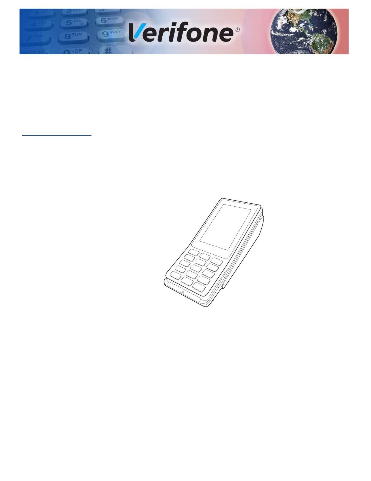
Front Functions
Figure 1 P400 Touch
The P400 includes the following features:
• Capacitive touch LCD display
• Secure keypad supporting 3x5 matrix containing 0-9, *, #, Cancel, Backspace/
Clear, and Enter keys.
• Supports telco-style format
• Dual-function Backspace/Clear key.
• Customer-entry for Cancel and Enter keys.
P400/P400 PLUS INSTALLATION GUIDE 9

OVERVIEW
Features and Benefits
Back Functions
Features and
Benefits
The rear of the P400 device shows the following:
• Cable connector compartment.
• Threaded grommets for attaching the mounting plate.
• A uSD and a dual-stack MSAM connectors built into the back of the unit to
support stored-value card programs or other merchant card requirements.
Exceptional Ease of Use and Ergonomics
• Sleek and stylish shape occupies minimal counter space.
• Bold, ergonomic design fits comfortably in the palm of a hand.
• Large, hard-rubber keys provide improved tactile feedback, minimizing errors
and maximizing ease-of-use for consumers of all ages.
• Intuitive telco-style interface and colored control keys simplify training and
reduce support requests.
• 320 (RGB) x 480 TFT (HVGA) display with a capacitive touch panel.
• Rugged and reliable design.
• Connects with most POS payment terminals.
• Supports payment transactions in a variety of payment environments.
Critical Security Protection
• Offers a choice of Master/Session or DUKPT key-management methods to
protect PIN-based transactions.
• Offers secure, reliable PIN input for expanding range of PIN-based
transactions.
• PCI-compliant for secure solutions, meeting the PED standard.
• Meets ISO and ANSI standards for PIN encryption, key management, and
MAC.
• Key injection simplified and secured with Verifone’s SecureKit key loading
software.
• Rugged and reliable design absorbs hard knocks found at point-of-sale
counters.
• Removable privacy shield offers option of supplemental physical security.
• Connects with most POS payment terminals, PCs, and ECRs.
• USB Connectivity that gives another option to connect with payment terminals,
personal computers, and electronic cash registers (ECRs).
10 P400/P400 PLUS INSTALLATION GUIDE

Setup
WARNI NG
CAUTION
CHAPTER 2
This chapter describes the setup procedure for the P400, in the following sections:
• Selecting Location
• PIN Protection Measures
• Unpacking Shipping Carton
• MSAM/uSD Cards
• Power Supply
• Cable Connections
• Smart Card Reader
• Magnetic Stripe Card Reader Use
• Contactless Transactions
• Optional Accessories
Selecting
Location
Environmental
Factors
Use the following guidelines to select the best location for the P400 device.
To Select a Location
Choose a location convenient for both merchant and client:
• Far from heavy metal objects,
• A flat support surface such as a countertop or a table,
• Near a power outlet and the terminal or computer that connects to the P400.
For safety, do not string cables or cords across a walkway.
• Do not use the unit where there is high heat, dust, humidity, moisture, or
caustic chemicals or oils.
• Keep the unit away from direct sunlight and anything that radiates heat, such
as a stove or a motor.
• Do not use the P400 outdoors.
The P400 is not waterproof or dustproof and is intended for indoor use only. Any
damage to the unit from exposure to rain or dust can void any warranty.
P400/P400 PLUS INSTALLATION GUIDE 11
SETUP
WARNI NG
CAUTION
PIN Protection Measures
Electrical
Considerations
Contactless
Considerations
• Avoid using this product during electrical storms.
• Do not use the P400 unit near water or in moist conditions.
• Disconnect the device from its POS terminal before cleaning.
Due to risk of electrical shock or terminal damage, do not use the terminal near
water, including a bathtub, wash bowl, kitchen sink or laundry tub, in a wet
basement, or near a swimming pool. Avoid using this product during electrical
storms. Avoid locations near electrical appliances or other devices that cause
excessive voltage fluctuations or emit electrical noise (for example, air
conditioners, neon signs, high frequency or magnetic security devices, or electric
motors).
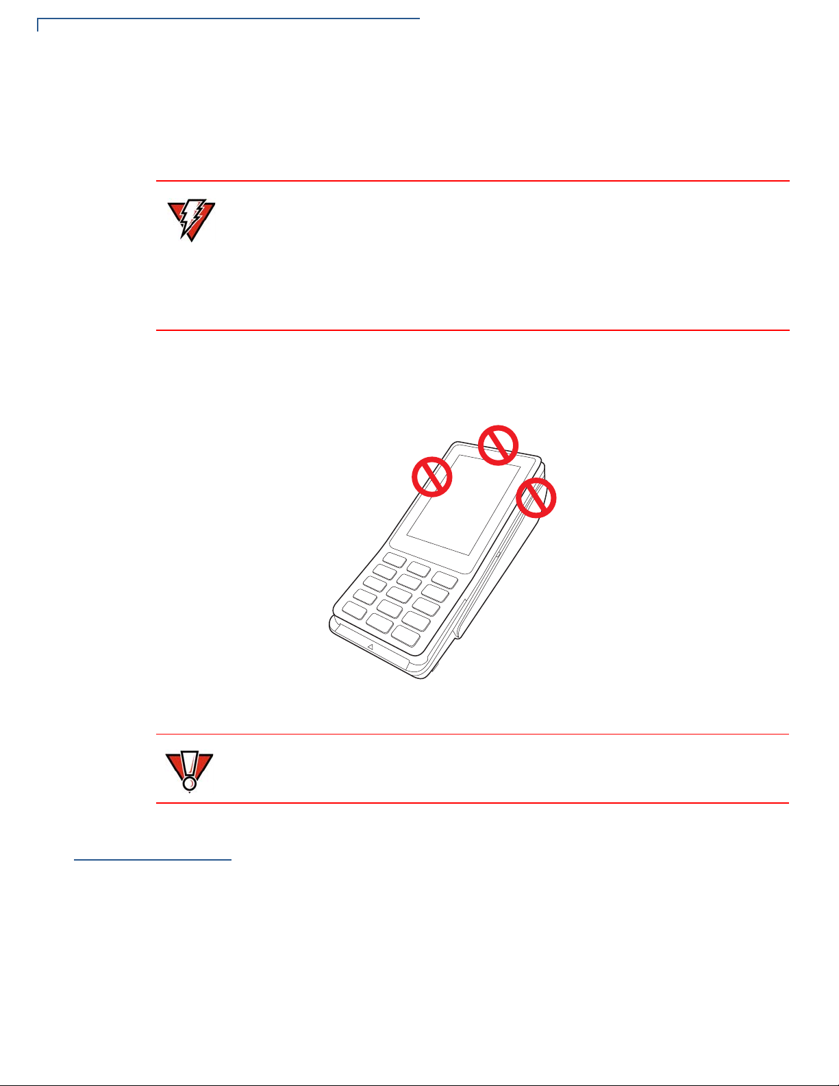
Avoid having metallic objects in proximity of the contactless antenna. If you need
to mount the terminal to vertical or inclined surfaces, use a flat, non-metallic
mounting plate.
PIN Protection
Measures
12 P400/P400 PLUS INSTALLATION GUIDE
Figure 2 Areas To Avoid Metal Contact
Using an enclosed metal frame or mount may negatively affect contactless
performance.
Use the following techniques to provide effective screening of PIN-entry devices
(PEDs) during the PIN entry process. You can use these methods in combination,
although in some cases a single method might suffice.
• Position the terminal on the check-in stand in such a way as to block visual
observation of the PIN-entry process. Examples include:
• Visual shields designed into the check-in stand. The shields may be solely
for shielding purposes, or may be part of the general check stand design.
• Position the PED so that it is angled in such a way that PIN spying is
difficult.

Unpacking Shipping Carton
CAUTION
• Install the PED on an adjustable stand that allows consumers to swivel the
terminal sideways and/or tilt it forwards/backwards to a position that makes
visual observation of the PIN-entry process difficult.
• Position in-store security cameras so that the PIN-entry keypad is not visible.
The following table describes the two preferred mounting methods and the
recommended measures to protect from PIN capture in four observation corridors:
Table 3 Mounting Methods and Protection Measures
SETUP
Ensuring User
Privacy
Method Cashier
Countertop
without stand
Countertop
with stand
Use signage
behind the
PED
No action
needed
Customer in
Queue
Install so that
customer is
between PED and
next in queue
Install so that
customer is
between PED and
next in queue
Customers
Elsewhere
No action
needed
No action
needed
On-site
Cameras
Do not install
within view of
cameras
Do not install
within view of
cameras
Verifone also recommends instruction of the cardholder regarding safe PIN-entry.
This can be done with a combination of:
• Signage on the PED
• Prompts on the display, possibly with a click-through screen
• Literature at the point of sale
• A logo for safe PIN-entry process.
Use the following guidelines to protect the user’s privacy when he enters his
personal identification number (PIN):
Unpacking
Shipping Carton
• The area of visibility should be no larger than a cone taken from the number 5
key at an angle of 45° and covering an area of 270° directly in front of the user.
• You can secure PIN entry by installing an optional Privacy Shield.
Carefully inspect the shipping carton and its contents for possible tampering or
damage.
1 Remove the P400 unit from the shipping carton. The standard package
contains the PIN pad only and does not include any other cables or
accessories. Refer
Accessories and Documentation to for more information
about P400 related accessories.
This device is a secure product and any tampering can cause it to cease to
function or operate in an unsecured manner.
2 Remove any protective plastic wrap and place the unit on a table or
countertop.
P400/P400 P
LUS INSTALLATION GUIDE 13
 Loading...