

Page 1
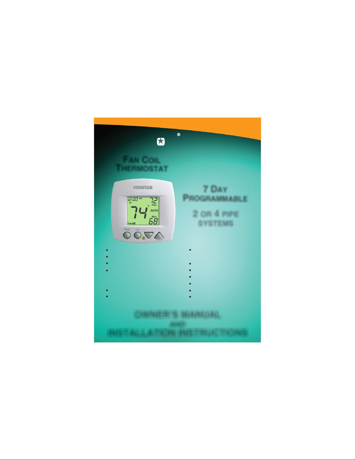
VENSTAR
FAN COIL
THERMOSTAT
FAN COIL
T1075
THERMOSTAT
7 DAY
PROGRAMMABLE
2 OR 4 PIPE
SYSTEMS
3 Occupied, 1 Unoccupied
Override capable
3 speed fan control
Auto 2-pipe changeover
when used with accessory
changeover sensor
Dry contact equipped
Backlit display
Works with most fan
coil systems - 24vac
Electric heat ready
Non-volatile memory
Dual or single setpoint
Keypad lockout
Remote sensor ready
Display F or C
OWNER’S MANUAL
AND
INSTALLATION INSTRUCTIONS
Page 2
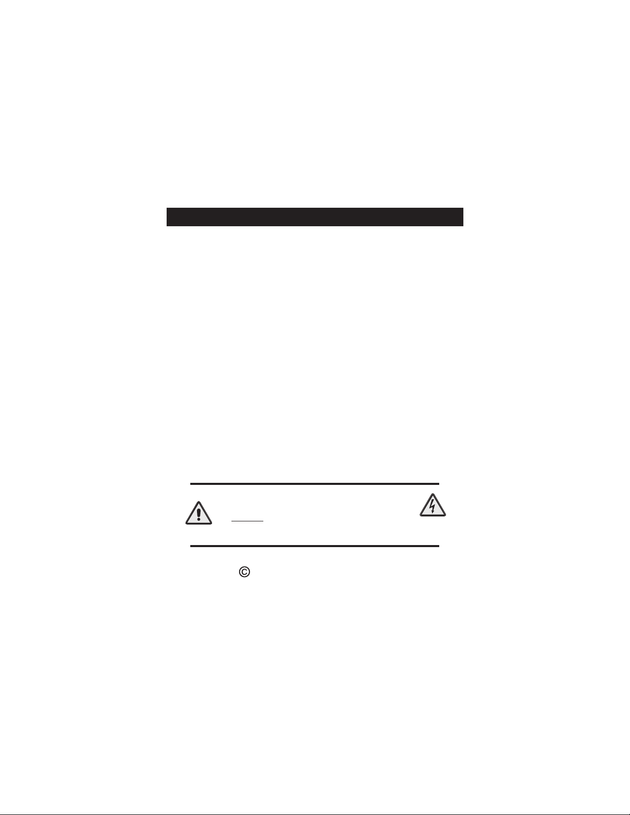
Table Of Contents
FRONT PANEL
DISPLAY
QUICK START Set the clock and go
SELECTING THE HEAT
OR COOL MODE
BASIC OPERATION
OVERRIDING THE DAILY
SCHEDULE
PROGRAMMING Occupied / Unoccupied
ADVANCED SETUP
ADVANCED SETUP TABLE
ABOUT ADVANCED FEATURES
& OPERATION
SAMPLE WIRING DIAGRAMS
WARRANTY
CAUTION
before removing the old therm-
Disconnect Power
to the Heater/Air Conditioner
ostat and installing the new
thermostat.
2
3
6
7
11
12
13
18
24
25
34
38
WARNING
Model T1075
Copyright 2012 Venstar, Inc
All Rights Reserved
Page 1
Page 3
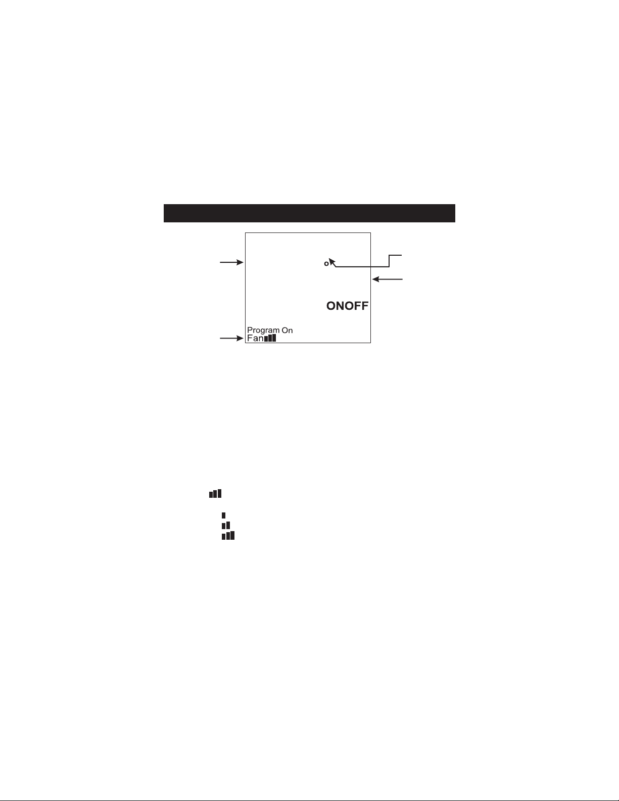
Front Panel
I2:00
Mo
1
Am
74
COOL
AUTO
72
Mode Fan
HEAT
70
2
3
4
1
Liquid Crystal Display
2
Up/Down Buttons
Mode Button
3
4
Fan/Override Button
5
Heat or Cool Indicator
5
Heat = Red, Cool = Green
Page 2
Page 4
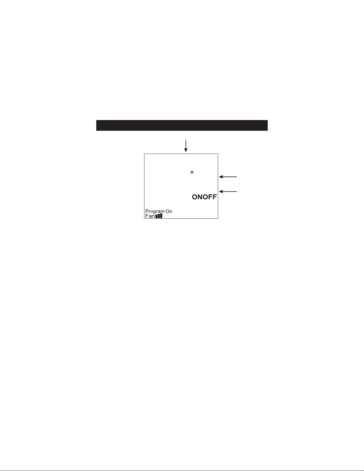
Display
2
4
1
3
OUTSIDE
1
1
1
Mode Indicators - Pages 7-10
4
Selects the operational mode of the equipment.
HEAT - Indicates the heating mode.
COOL - Indicates the cooling mode.
AUTO - Indicates the system will automatically
changeover between heat and cool modes
as the temperature varies.
PROGRAM ON - Indicates the time period
program is enabled to run.
OFF - Indicates heating and cooling are turned off.
Clock with Day of the Week - Page 6
2
Indicates the current time and day. This clock is
also used to program the time period schedules.
3
Room Temperature Display
Indicates current room temperature.
4
Desired Set Temperature - Page 11
Indicates desired room temperature(s).
Page 3
Page 5
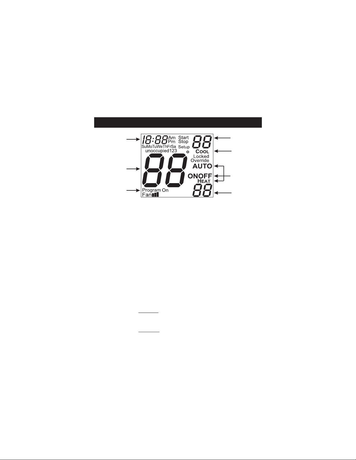
Display
Am
Start
Pm
123
Stop
Setup
88
COOL
Locked
Override
AUTO
OUTSIDE
7
5
I2:00
SuMoTuWeThFrSa
6
unoccupied
88
HEAT
8
5
Override icon - Pages 12 & 22
Indicates the program is currently being overridden
for up to six hours.
Occupied & Unoccupied icons - Pages 13-16
6
Indicates the program number: Occupied 1,2,3 or
Unoccupied.
Setup icon - Pages 18-23
7
Indicates the thermostat is in the advanced setup
mode.
8
Fan icon - Page 11
Indicates fan operation.
Fan = low speed
Fan = medium speed
Fan = high speed
When only the Fan icon is displayed, the fan is in
the Auto mode and will run only when necessary to
heat or cool.
Page 4
88
Page 6
Display
9
Am
Start
Pm
123
Stop
Setup
88
COOL
Locked
Override
AUTO
OUTSIDE
HEAT
I2:00
SuMoTuWeThFrSa
unoccupied
88
88
Start & Stop icons - Pages 14-16
9
Appear when programming occupied time periods.
Locked icon - Page 31
10
Indicates keypad has been locked.
Outside icon - Page 32
11
Indicates the temperature displayed is from the
optional outside sensor.
10
11
Page 5
Page 7
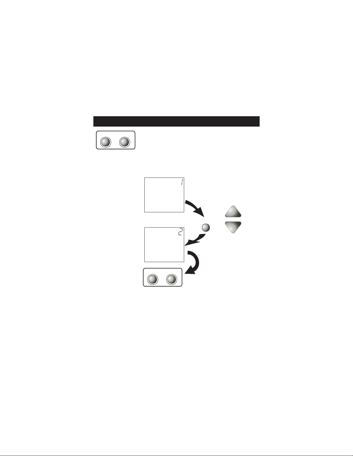
Quick Start Set the Clock and Go
MODE FAN
Press the MODE and FAN buttons
at the same time for two seconds
to enter Setup screens.
Setting the Clock
Tip: To change
hours quickly,
press and hold
the FAN button
and press the
UP or DOWN
button.
Setting the Day
Press the MODE
and FAN buttons
at the same time
t o r e t u r n t o
normal operation.
Am
I2:00
MODE FAN
Setup
SetupMo
During Setup and
Programming:
Pressing the UP or
DOWN button will
modify the flashing
selection.
To adjust the
Clock or Day use
Press
MODE
buttons.
The thermostat is preprogrammed from the factory to
operate a 4 pipe system without the need for further
programming. To optimize the installation of this
thermostat for a 2 pipe system, follow the instructions
in the Advanced Setup section. Page 19
Page 6
Page 8
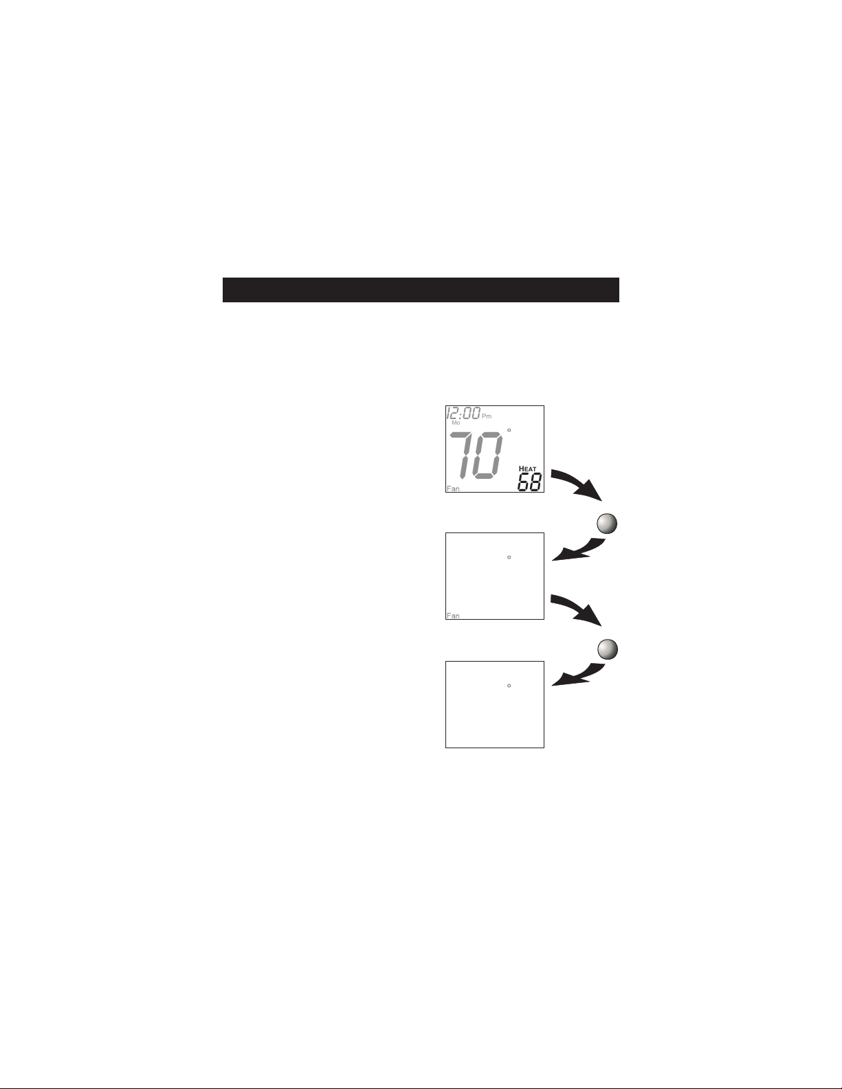
Selecting the Heat or Cool Mode 4-Pipe Operation
Select Mode by Pressing the MODE Button
Pm
Heating Only
The HEAT setting indicates
the temperature the room
has to reach before the
heating source will turn
on to heat the room.
Cooling Only
The COOL setting indicates
the temperature the room
has to reach before the
cooling source will turn
on to cool the room.
Heating or Cooling
AUTO will automatically
select heat or cool based
on room temperature
demand.
Time Schedule for
Heating or Cooling
Program On will activate
the stored timer operation
for the heating and cooling
setpoints (occupied or
unoccupied periods).
Off
OFF indicates both heating
and cooling are turned off.
I2:00
Mo
70
Pm
I2:00
Mo
70
Pm
I2:00
Mo
70
Pm
I2:00
Mo
occupied
1
70
ProgramOn
Pm
I2:00
Mo
HEAT
68
76
COOL
76
COOL
AUTO
HEAT
68
76
COOL
HEAT
68
OFF
Press
MODE
Press
MODE
Press
MODE
Press
MODE
70
Page 7
Page 9
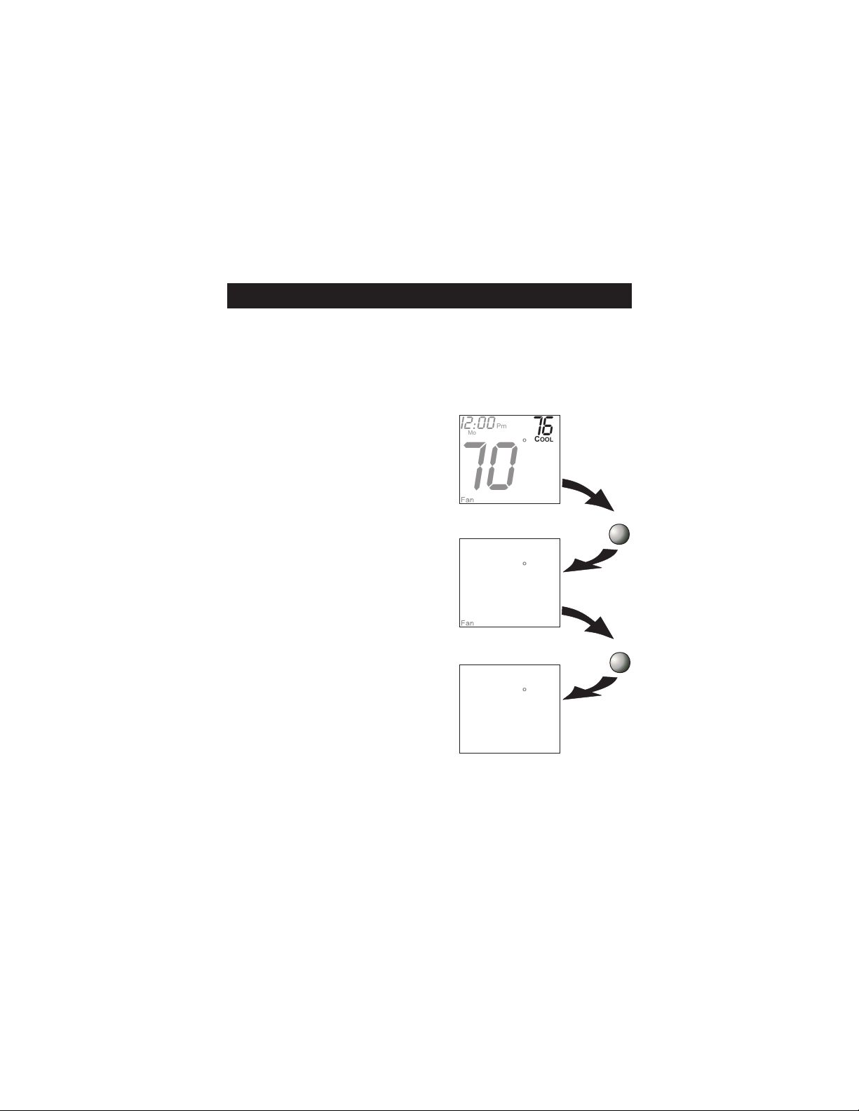
Selecting the Heat or Cool Mode 2-Pipe Operation
Heat Only
Step #6 = 1 in the Advanced Setup section,
page 19.
Heating Only
The HEAT setting indicates
the temperature the room
has to reach before the
heating source will turn
on to heat the room.
Time Schedule for
Heating or Cooling
Program On will activate
the stored timer operation
for the heating and cooling
setpoints (occupied or
unoccupied periods).
Off
OFF indicates both heating
and cooling are turned off.
Page 8
Pm
I2:00
Mo
70
Pm
I2:00
Mo
occupied
1
70
ProgramOn
Pm
I2:00
Mo
70
HEAT
68
Press
MODE
HEAT
68
Press
MODE
OFF
Page 10
Selecting the Heat or Cool Mode 2-Pipe Operation
Cool Only
Step #6 = 2 in the Advanced Setup section,
page 19.
Cooling Only
The COOL setting indicates
the temperature the room
has to reach before the
cooling source will turn
on to cool the room.
Time Schedule for
Heating or Cooling
Program On will activate
the stored timer operation
for the heating and cooling
setpoints (occupied or
unoccupied periods).
Off
OFF indicates both heating
and cooling are turned off.
Page 9
Pm
I2:00
Mo
70
Pm
I2:00
Mo
occupied
1
70
ProgramOn
Pm
I2:00
Mo
70
76
COOL
76
COOL
OFF
Press
MODE
Press
MODE
Page 11
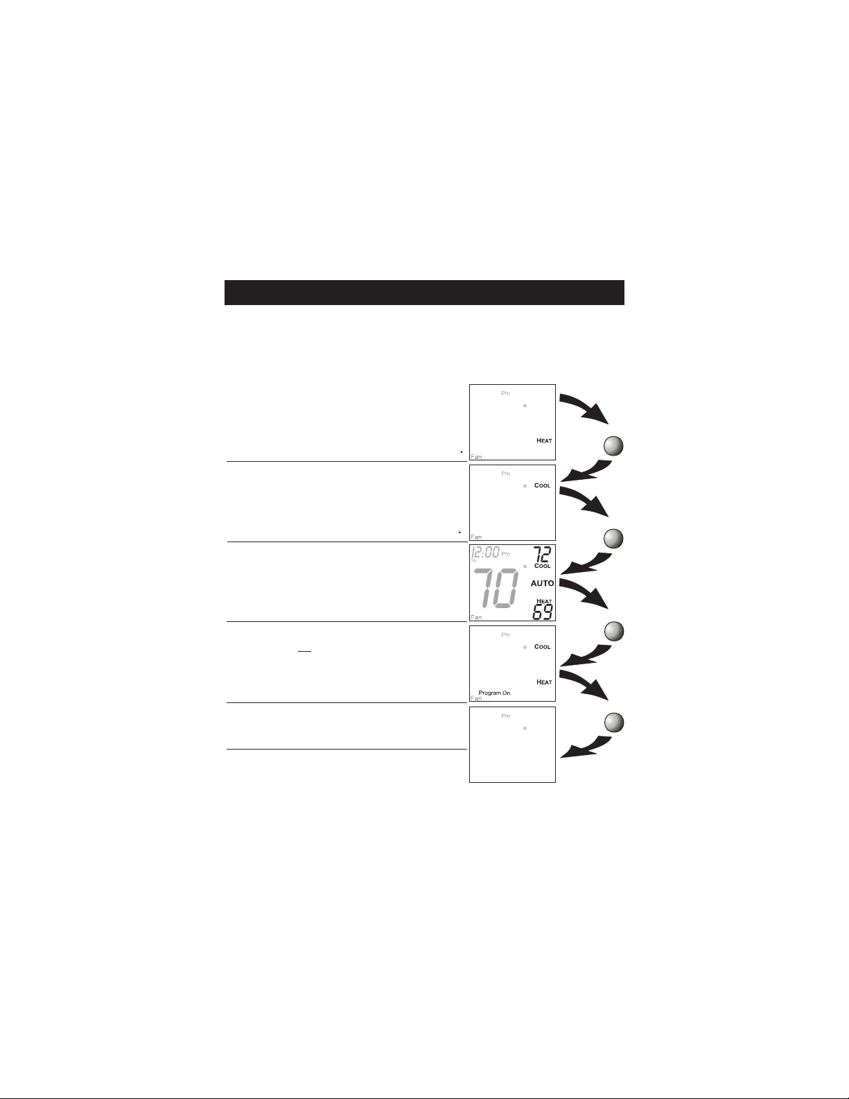
Selecting the Heat or Cool Mode 2-Pipe Operation
Heating and/or Cooling
Step #6 = 3 in Advanced Setup (page 19), and the
accessory changeover sensor (ACC-SENFC) is used.
Step #6 = 4 or 5 in Advanced Setup (page 19).
Operation is the same as a 4-pipe system (page 7).
HEAT indicates the temperature
the room has to reach before the
heating source energizes. If the
water supply is cold, this screen
and heating would be locked out.
COOL indicates the temperature
the room has to reach before the
cooling source energizes. If the
water supply is hot, this screen
and cooling would be locked out.
If step #6 = 3, this
screen will not appear.
AUTO will automatically select
heat or cool based on the room
temperature demand.
If step #6 = 3, only
heat or cool will appear.
Program On will activate the
stored timer operation for the
heating and cooling setpoints.
OFF indicates both heating and
cooling are turned off.
Note: If the water temperature is
changed during the year, the thermostat will then automatically lock
out the incorrect mode.
Page 10
I2:00
Su
70
I2:00
Su
70
I2:00
Su
70
I2:00
Su
occupied
1
70
I2:00
Su
70
69
72
72
69
73
70
OFF
Press
MODE
Press
MODE
Press
MODE
Press
MODE
Page 12
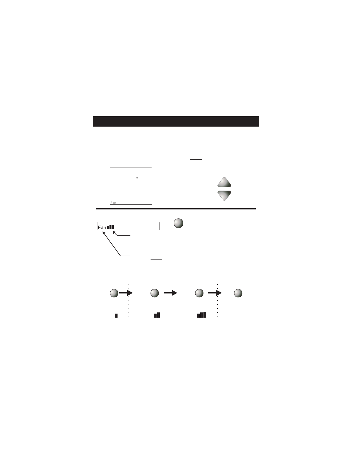
Basic Operation
Selecting Your Desired Temperature
(adjusting the setpoints)
AUTO OR PROGRAM MODE
Pressing the UP or DOWN button when both Heat & Cool
setpoints are visable will adjust both the heat and cool
set temperatures simultaneously.
Pm
I2:00
Mo
70
Fan Operation
76
COOL
AUTO
HEAT
68
Press
FAN
Adjust the desired
set temperature with the
buttons.
Pressing the FAN button will run the fan in
low, medium, or high speed continuously
(see below and page 29).
When only the Fan icon is displayed, the fan
is in the Auto mode and will run only when
necessary to heat or cool (see below and
page 29).
Press
FAN
Low Speed Medium Speed
Fan Fan Fan
FAN
Press
Press
FAN
Press
FAN
High Speed Auto
Fan
Note: If the thermostat is placed in the Off mode, the fan
will de-energize.
Page 11
Page 13

Basic Operation
Overriding the Daily Schedule
Pressing and holding the FAN button for 5 seconds
may be used to interrupt the normal time schedule
programming of the thermostat. The override feature
may only be used when the thermostat is running the
time schedule, in Program On mode.
Unoccupied Operation - During programmed,
unoccupied periods pressing and holding the FAN
button for 5 seconds will temporarily force the
thermostat into Occupied 1 comfort settings for one
to six hours (step #14, page 22). The Override icon
will be illuminated during this time. If you press and
hold the FAN button while the thermostat is
currently overriding the daily schedule, this will
reset the timer, returning the thermostat to the
correct time period program for the day.
Occupied Operation - Pressing and holding the
FAN button for 5 seconds during a programmed
Occupied time period will have no effect.
7:56
O
85
7:56
55
74
Override
68
Page 12
O
O
O
FAN FOR
5 SECONDS
Press
Page 14

Programming Occupied & Unoccupied Periods
Press the MODE button. While holding
MODE
MODE, press the UP button for two
se co n d s to en te r t i me pe r i o d
programming.
Select the maximum # of
occupied periods to be
occupied 1
used on any one day.
Typically, most installations
use only Occupied 1.
(1,2 or 3)
Ad ju s t t he co o l i ng
occupied
74
1
MODE
COOL
setpoint for Occupied 1.
(35 - 99 )
MODE
74
1
Ad ju s t t he he at in g
occupied
COOL
setpoint for Occupied 1.
(35 - 99 )
HEAT
72
MODE
Press
Press
Press
Adj ust th e co o li n g
setpoint for unoccupied
periods.
(35 - 99, OF )
Page 13
unoccupied
Continued
85
COOL
Press
MODE
Page 15

Programming Occupied & Unoccupied Periods
Adjust the heating setpoint for Unoccupied
periods.
(OF, 35 - 99 )
Select day of the
week to program.
(Mo - Su)
Adjust the start time
for O c cupie d 1.
Adjust the stop time
for Occu p ied 1.
On
Select Occupied 1
to run on this day
(On), or not to run
Off
on this day (Off).
Page 14
unoccupied
Mo
occupied
Am
7:00
Mo
occupied
Pm
6:00
Mo
1
occupied
Mo
1
occupied
Continued
85
COOL
HEAT
55
Start
1
Stop
ON
Press
MODE
Press
MODE
Press
MODE
Press
MODE
Press
MODE
Page 16

Programming Occupied & Unoccupied Periods
The copy command becomes available after the
maximum # of occupied periods are programmed
in a day. This example uses 1 as the maximum
occupied periods ever programmed in one day.
Yes
Select Yes or No to copy
Tu
th e p re v i ou s d ay ’ s
program to this day.
Press
MODE
No
If Yes is selected:
Selecting Yes, then pressing mode
will copy the previous day’s program
and then will ask the same copy
Co
Py
If No is
selected:
question again. If yes is selected
each time, this routine will repeat
until Saturday is copied to Sunday.
After Saturday is copied to Sunday,
the copy command is unavailable.
Tu
occupied
Select day of the
1
week for Occupied 1.
(Tu - Mo)
Press
MODE
Press
MODE
Adjust the start time
fo r o c c u pi ed 1.
Page 15
9:00
Tu
occupied
Am
Start
1
Continued
Press
MODE
Page 17

Programming Occupied & Unoccupied Periods
Pm
5:00
Tu
occupied
Stop
1
Adjust the stop time
fo r oc cu p ie d 1 .
On
Select Occupied 1 to
Tu
occupied
1
run on this day (On),
Off
Yes
or not to run this day
(Off).
Select Yes or No to
We
ON
Press
MODE
copy the previous
day’s program to this
No
day.
Co
Py
If Yes is selected:
Press
MODE
Selecting Yes, then pressing mode
will copy the previous day’s program
and then will ask the same copy
question again. If yes is selected
each time, this routine will repeat
until Saturday is copied to Sunday.
After Saturday is copied to Sunday,
the copy command is unavailable.
If no is selected, as in previous steps flashing prompts for
input will appear for start and stop times for Occupied 1.
If more than one occupied period was selected on page
13, then cool/heat setpoints, and start/stop times for
additional occupied periods will be prompted.
Page 16
If No is
selected:
Press
MODE
Page 18

Programming Occupied & Unoccupied Periods
PROGRAMMING NOTES
You will be prompted to enter both heat and cool
setpoints even if the thermostat is configured for
heat only, or cool only.
If only 1 Occupied period is selected, the Occupied 2 & 3
steps will be skipped. Further, if only 2 occupieds are
selected, the Occupied 3 steps will be skipped.
Heat & Cool setpoints for Occupied 1 are the same for
each day. Heat & Cool setpoints for Occupied 2 & 3 can
be adjusted differently for each day, if desired.
If the start time is set for later than the stop time, the
program will run from the start time to midnight and from
midnight to the stop time on the same day. For example:
9:00pm start, 8:00am stop, on Monday. This program
will run from 12:00am Monday to 8:00am and
again from 9:00pm to 11:59pm on Monday.
The Unoccupied settings take effect at all times when:
(1) the program is on and (2) the current time is outside
an occupied period. For this reason start and stop
times are not necessary for unoccupied.
If the same start and stop times are programmed in for
an occupied period, then it will run 24 hours.
If one occupied period starts and stops within another
occupied period, the lower occupied # has priority.
example: If Occupied 3 is programmed to be “on” 24
hours, and Occupied 2 is programmed to run that day,
then Occupied 2 settings will take precedence during
that time.
During the Override mode (see page 12), the Occupied 1
Heat & Cool setpoints are used.
For
Page 17
Page 19

Advanced Setup
MODE FAN
Press the MODE and
FAN buttons at the
same time for 10
seconds to enter
A d v a n c e d S e t up
screens.
Adjust the time of day.
I2:00
Tip: To change hours
quickly, press and hold
the FAN button and
press the UP or DOWN
buttons.
Mo
Select the day of the
week.
Display On
Select Display operation:
On = Full Display
Off = Minimal display
Display Off
Note: #3 & #4 require accessory ACC-SENFC
changeover sensor
See Page 29
Page 18
NOTE: Each step
# is located at the
top right corner of
the display for easy
reference.
Am
Setup
I
MODE
Setup
2
MODE
Setup
3
ON
MODE
Continued
Press
Press
Press
Page 20

Advanced Setup
Select Display operation:
1 = Single Setpoint
2 = Dual Setpoint
See Page 33
Note: When Single Setpoint is
selected, the heating or cooling
setpoint will always be displayed. To display the
room temperature, press and hold the MODE
button for two seconds. The degree icon will
blink when the large number is displaying room
temperature and will remain solid when displaying the heating or cooling setpoint.
4
Select fan coil system
type:
2 = 2-pipe fan coil
4 = 4-pipe fan coil
2
Step #6 only appears if step #5 = 2.
2 PIPE SYSTEM OPERATION
1= Heat only system
2= Cool only system
3= Heat/Cool Auto
changeover
4= Heat/Cool Aux Electric
heat, Lockout Electric Heat
when Hot Water is available
5= Heat/Cool total electric
heat, no Hot Water, only
Electric Heat.
Page 19
2
I
Setup
Setup
4
Setup
Continued
4
5
6
Press
MODE
Press
MODE
Press
MODE
Page 21

Advanced Setup
Select operation when
fan is in the Auto mode:
On
On = continuous low
speed fan
Off = only energize
during a heating or
Off
cooling cycle.
See Page 29, Note #2
7
AUTO
Press
MODE
Select Fan Coil Type
On
On = Carrier or IEC
fan coil using a
33ZCRLYBRD relay
board.
Off
Off = Conventional
3 speed fan coil system.
See Page 33 for further explanation
Adjust the deadband
for the 1st stage.
(1 - 6 )
See Page 26
Page 20
Setup
2
Continued
8
Press
MODE
9
Press
MODE
Page 22

Advanced Setup
Step #10 will not appear if step #6 = 1 or 2.
Adjust the minimum
difference between
cooling & heating
setpoints.
(0 - 6 )
On
Select backlight operation:
On - Light continuously
Off - Light for 8 seconds
after a button press
Off
C
Se le c t t he rm os ta t
operation in degrees
Fahrenheit or Celsius.
F
Sensor Reading
On
Select sensor operation:
On =
read only Duct
sensor
Off = control to Duct
Off
sensor
Setup
2
Setup
Setup
72
Setup
I0
COOL
HEAT
I I
I2
I3
OUTSIDE
Press
MODE
Press
MODE
Press
MODE
Press
MODE
Page 21
Continued
Page 23

Advanced Setup
Adjust the amount of
time override will be
2 00
Setup
a c t i v e d u r i n g t h e
unoccupied time period.
(0 - 6 hours)
NO
Setup
Dry Contact
NO = Normally Open
NC = Normally Closed
NC
Occupied
Select Dry Contact operation:
Occupied = the thermostat will enter the Occupied mode when the Dry
Unoccupied
Contact Contact is closed.
Unoccupied = the thermostat will enter the
Unoccupied mode when the Dry Contact is closed.
See Page 27
occupied
Setup
Continued
I4
Override
Press
MODE
I5
Press
MODE
I6
MODE
Page 22
Page 24

Advanced Setup
Unoccupied Setpoints
Select Dry Contact
Unoccupied operation:
Unoccupied = when the
Dry Contact is closed,
Off
the thermostat will control to the Unoccupied setpoints.
Off = when the Dry Contact is
closed, the thermostat will turn
off.
After programming is complete, press the
MODE and FAN buttons at the same time
to leave the Setup screens.
If no buttons are pressed, the display will
leave the setup screens after 60 seconds.
unoccupied
85
MODE FAN
Setup
I7
55
Page 23
Page 25

Advanced Setup
Advanced Setups - Table
Step
1 Time of Day
2 Day of Week
3 Display Blanking
4 Single or Dual Setpoint
5 2 or 4 Pipe System
6 2 Pipe System Operation
7 Fan Auto Operation
8 Fan Coil Type
9 1st Stage Deadband
10 Minimum Heat/Cool
11 Backlight
12 Degrees F or C
13 Sensor Operation
14 Override Timer Length
15 Dry Contact Polarity
16 Dry Contact Operation
17 Dry Contact Operation
Description
Page 24
Range
24 Hour
Mo - Su
On / Off
1 /2
2 / 4
1 - 5
On / Off
On - Off
1 - 6
0 - 6
On / Off
F / C
On / Off
0 - 6 Hours
Occ. / Unocc.
Unocc. / Occ.
Unocc. / Off
Default
12:00am
Mo
On
2
2
1
Off
Off
2
2
Off
F
Off
2 Hours
NO /NC
Occ.
Unocc.
Page 26

About Advanced Features & Operation
CALIBRATION - Under normal circumstances it will not
be necessary to adjust the calibration of the temperature
sensor. If calibration is required, please contact a trained
HVAC technician to correctly perform the following
procedure.
1
MODE
Place the thermostat in the OFF
I2:00
Mo
Pm
mode.
72
Am
Start
2
MODE
Press button.
and hold the MODE
While holding the MODE button,
press and hold the DOWN button
for 5 seconds. All icons will
appear on the display.
Pm
unoccupied
Stop
Setup
123
I2:00
SuMoTuWeThFrSa
88
OFF
88
COOL
Locked
Override
AUTO
OUTSIDE
HEAT
88
3
Press the MODE button once. The
600
thermostat temperature will be
displayed and may be calibrated
72
Pm
I2:00
Mo
4
MODE
using the UP or DOWN button.
After calibration is complete, press
the MODE button once to save
your changes and return to normal
operation.
72
CLOCK BACKUP - In the event of a power loss, the
thermostat’s internal clock will continue to keep proper
time for a minimum of 48 hours without external power
or batteries.
Page 25
HEAT
60
OFF
Page 27

About Advanced Features & Operation
DEADBAND OPERATION - Controls one Heat and
one Cool stage with a three speed fan (see below).
The low speed fan for heat or cool is turned on when:
The temperature spread from the setpoint is equal to
or greater than: the setpoint plus the 1st stage dead-
band (step #9, page 20). This 1st stage deadband is
adjustable from 1-6 degrees and the default is two
degrees.
The medium speed fan for heat or cool is turned on
when: The temperature spread from the setpoint is
equal to or greater than: the setpoint plus the 1st stage
deadband (step #9, page 20), plus the 2nd stage deadband. This 2nd stage deadband is fixed at one degree
and is not adjustable.
The high speed fan for heat or cool is turned on when:
The temperature spread from the setpoint is equal to or
greater than: the setpoint plus the 1st stage deadband
(step #8, page 20), plus the 2nd stage deadband, plus
the 3rd stage deadband. This 3rd stage deadband is
fixed at one degree and is not adjustable.
Heating
1-6
DB 31DB 21DB 1
Med-
Hi-
speed
speed
fan
DECREASE INCREASE
speed
fan
Heat
Lo-
fan
SP
TEMPERATURE
Cool
SP
1-6
DB 1
Cooling
DB 21DB 3
Lo-
speed
speed
fan
Med-
fan
1
Hi-
speed
fan
The above figure assumes the minimum on time for the
prior stage has been met to allow the next stage to turn
on, once the deadbands have been exceeded.
Page 26
Page 28

About Advanced Features & Operation
DRY CONTACT SWITCH -
This feature allows an external device such as a Central Time Clock, Occupancy Sensor, or a Telephone activated device to force
one or more thermostats into an Occupied or
Unoccupied mode (steps #15 and 16, page 22).
When the CK1 and R terminals are shorted together,
and the thermostat is programmed for Unoccupied
operation (step #16, page 22), the thermostat will be
forced into Unoccupied setpoints or Off (step#17, page 23)
and the Unoccupied icon will appear on the display.
Note: The thermostat must be in Program On mode
for this feature to have any effect.
Important Note: For control of multiple
thermostats by 1 source, refer to page 37
‘Potential Phasing Problems’ before
installation.
TERMINAL CONNECTIONS
5
+
R
S
RS
RY1G3
4Z95
24V. 60HZ
NEC CLASS 2
G
ENCLOSED
ENERGY
MANAGEMENT
EQUPIMENT
C
W1
G2
MODEL: T1075
X072500204
MADE IN CHINA
H2O
CK1
Connect wires to a time clock or other device to
force the thermostat into Occupied 1 or
Unoccupied settings.
Page 27
Page 29

About Advanced Features & Operation
FACTORY DEFAULTS -
If, for any reason, you desire to
return all the stored settings back to the factory default
settings, follow the instructions below.
WARNING: This will reset all Time Period and Advanced Programming to the default settings. Any
information entered prior to this reset will be
permanently lost.
1
MODE
Place the thermostat in the OFF
I2:00
Mo
Pm
mode.
72
Am
Start
2
MODE
3
FAN
4
MODE
Press button.
and hold the MODE
While holding the MODE button,
press and hold the DOWN button
for 5 seconds. All icons will
appear on the display.
After all of the icons appear,
release the MODE and DOWN
buttons. Then press and hold the
FAN button for 2 seconds.
After the letters Fd appear on the
display (Factory Default), release
the FAN button. Press the MODE
button twice to return to normal
operation.
Pm
unoccupied
Stop
Setup
123
I2:00
SuMoTuWeThFrSa
88
Pm
I2:00
Mo
72
OFF
88
COOL
Locked
Override
AUTO
OUTSIDE
HEAT
88
OFF
Page 28
Page 30

About Advanced Features & Operation
FAN OPERATION - Fan operation is available in four
different modes:
Fan: When only the fan icon is displayed, this
indicates that the fan is in the Auto mode, will only
energize during a heating or cooling cycle, and will
modulate fan speeds based on temperature demand
(see page 26).
Fan , Fan , or Fan : Pressing the FAN button
will cause the low, medium, or high speed fan icon to
appear (see page 11), indicating that the fan will run
continuously. The fan will de-energize if the thermostat is placed in the Off mode or an unoccupied time
period (see page 26).
Notes:
1) If a Duct sensor is connected to this thermostat,
then the fan should be programmed for continuous
operation (step #7, page 20). This will provide airflow
over the Duct sensor and provide more accurate
temperature readings.
2) If the fan is programmed for continuous operation
(step #7, page 20), the low speed fan will run continuously when the fan is in the Auto mode and during
occupied time periods, but will de-energize if the
thermostat is placed in Off mode or Unoccupied.
MINIMAL DISPLAY - When the thermostat is programmed for a minimal display (step #3, page 18), only the
time of day will appear. When a button is pressed the
full, normal display will appear for 10 seconds.
Page 29
Page 31

About Advanced Features & Operation
ENERGY SAVING SMART FAN matically de-energizes the fan during an Unoccupied
time period, except when necessary to heat or cool
(see page 29).
This feature auto-
Pm
I2:00
Mo
unoccupied
70
76
COOL
HEAT
68
Note: The fan will not de-energize during an Unoccupied time period if it has been programmed for
continuous operation (step #7, page 20).
HEAT/COOL DIFFERENTIAL - The Heat and Cool setpoints will not be allowed to come any closer to each
other than the value set in Advanced Setup step #10, on
page 21. This minimum difference is enforced during
Auto-changeover and Program On operation.
Note: To increase the spread between the heating and
cooling setpoints in the Auto-changeover mode press
the MODE button until only the heat setpoint is displayed; adjust to the desired setpoint. Press the MODE
button until only the cool setpoint is displayed; adjust to
the desired setpoint. Press the MODE button again to
enter the Auto-changeover mode where both the heat
and cool setpoints are displayed.
Page 30
Page 32

About Advanced Features & Operation
KEYPAD LOCKOUT - To prevent unauthorized use of
the thermostat, the front panel buttons may be disabled.
To disable, or ‘lock’ the keypad, press and hold the
MODE button. While holding the MODE button, press
the UP and DOWN buttons together. The LOCKED icon
will appear on the display, then release the buttons.
Press all three
buttons in the order
I2:00
Mo
occupied
Pm
76
1
COOL
Locked
outlined above for
keypad lockout
MODE
72
Program
Fan
HEAT
On
68
To unlock the keypad, press and hold the MODE button.
While holding the MODE button, press the UP and
DOWN buttons together. The LOCKED icon will disappear from the display, then release the buttons.
LOCKING COVER (included)
w/Tamper Proof Screws
I2:00
Mo
72
Mode Fan
Am
74
COOL
AUTO
HEAT
70
Am
I2:00
Mo
72
74
COOL
AUTO
HEAT
70
Page 31
Page 33

About Advanced Features & Operation
OUTSIDE SENSOR - To view an Outside Sensor
(step #13, page 21), enter the Advanced Setup by
pressing and holding the MODE button. While
holding MODE, press the FAN button for 5 seconds
to enter Setup screens. Advance to setup step #13
by repeatedly pressing the MODE button. If an
optional outside sensor is connected, the outside
temperature will appear in the clock display.
DUCT SENSOR (P/N ACC0402) - The
thermostat is programmed from the factory to
automatically recognize when a Duct Sensor is
connected (step #13, page 21).
Digital Sensor
High Temp. Heat
Shrink Tubing
5’ Plenum Rated
Cable
White wire
Black wire
Duct Sensor connections are illustrated on page 36.
Note: If a Duct sensor is connected to this thermostat, then the fan should be programmed for
continuous operation (step #7, page 20). This will
provide airflow over the Duct sensor and provide
more accurate temperature readings.
Page 32
Page 34

About Advanced Features & Operation
SINGLE SETPOINT BEHAVIOR - When configured
for Single Setpoint operation (step #4, page 19), the
degree icon will blink when the large number is displaying room temperature and will remain solid when displaying the heating or cooling setpoint. In the Auto and
Program On modes the deadband is enforced both
above and below the setpoint. To avoid short cycling,
a deadband of at least two degrees is recommended
(step #9, page 20). To display the room temperature
press and hold the MODE button for two seconds.
Release the MODE button to return to the normal
display.
FAN COIL TYPE - This step instructs the thermostat
how to set the G, G2, and G3 outputs to yield the
desired fan speeds. Since this a low voltage
thermostat, the fan coil should have multiple relays or
contactors to supply the voltages needed for the fan
motor. Most fan coils will have 3 relays and require
only one relay to be driven at a time. However,
many models of Carrier or IEC fan coils contain a
relay board with special logic that requires different
output settings from the thermostat. If there is any
question, please contact the fan coil manufacturer.
Step 8 = OFF Step 8 = ON
Speed
LO
MED
HI
G
ON
G2
ON
G3
ON
Page 33
Speed
LO
MED
HI
G
ON
ON
ON
G2
ON
G3
ON
Page 35

Sample Wiring Diagram
2-Pipe, Low Voltage Valve, H2O Changeover Sensor
Thermostat
R
G
Y1
G3
W1
G2
C
H2O
C
R
H O Changeover Sensor
2
ACC-SENFC
Page 34
If 2-pipe with auxiliary
electric heat
R
VEH
C
24vac
24 Volt Water
Valve
Generic Relay Board
G
G
L
G2/(W)
G2
M
G3/(Y)
G3
H
COM
COM
LO
LO (L1)
L1 (N/A)
HI (HI)
MED (MED)
Page 36

Sample Wiring Diagram
4-Pipe, Low Voltage Valves, Duct Temperature
Sensor & Dry Contact
Duct Sensor
ACC0402
Thermostat
Dry Contact
H2O
RS
G3
W1
G2
Ck1
Important Note: If a
Duct sensor is conn-
RS
RS GND
ected to this thermostat
it is suggested that the
fan be programmed for
continuous operation
(step #7, page 20 of the
Owner’s Manual).
Connect directly to R
terminal on backplate.
R
G
Y1
H C
C
R
C
24vac
24 Volt Water
Valves
C
R
G
G
G2(W)
G3(Y)
COM
G2/(W)
G3/(Y)
COM
LO (L1)
L1 (N/A)
HI (HI)
MED (MED)
LO
Page 35
Page 37

Sample Wiring Diagram
Connection Diagram for Duct Sensor to
T1075 Fan Coil Thermostat
Digital Sensor
High Temp. Heat
Shrink Tubing
5’ Plenum Rated
Cable
White
Black
RS
R
G
Y1
G3
W1
G2
C
Note: It is important to
the black wire from the Duct
Sensor directly to the R
terminal on the thermostat
backplate.
Thermostat
connect
Page 36
Page 38

Sample Time Clock Wiring Diagram
Important Information About:
Auxiliary Input Control and Multiple HVAC Control
CAUTION
When using the auxiliary input (CK1 & R) or controlling multiple
HVAC units with a
transformer phasing problems that will
operation. Connecting transformers that are not phased
correctly may result in a direct short, which could damage the
transformers and/or the
if the units share a common ground with
transformers.
SOLUTION: If possible, phase all HVAC units together.
If phasing is impractical,
the transformers. To isolate the auxiliary
transformer for the auxiliary control device, usually a time clock.
Connect the device to an isolation relay coil. Connect one set
of isolated contacts to
See diagram A.
Diagram A- Auxiliary Control
110vac Isolation Relay
Additional relays may be used. Relay coils must be wired in parallel.
Potential Phasing Problems
single thermostat, it is possible to encounter
interfere with thermostat
thermostats. Phasing problems are likely
secondary grounded
isolation relays may be used to isolate
input, use a separate
each thermostat at CK1 and R.
Coil
WARNING
CK 1
Thermostat
R
CK 1
Thermostat
R
CK 1
Thermostat
R
Page 37
Page 39

Warranty
One-Year Warranty - This Product is warranted to be free from defects in material and
workmanship. If it appears within one year from the date of original installation, whether or not
actual use begins on that date, that the product does not meet this warranty, a new or
remanufactured part, at the manufacturer’s sole option to replace any defective part, will be
provided without charge for the part itself provided the defective part is returned to the distributor
through a qualified servicing dealer.
THIS WARRANTY DOES NOT INCLUDE LABOR OR OTHER COSTS incurred for diagnosing, repairing,
removing, installing, shipping, servicing or handling of either defective parts or replacement
parts. Such costs may be covered by a separate warranty provided by the installer.
THIS WARRANTY APPLIES ONLY TO PRODUCTS IN THEIR ORIGINAL INSTALLATION LOCATION AND
BECOMES VOID UPON REINSTALLATION.
LIMITATIONS OF WARRANTIES – ALL IMPLIED WARRANTIES (INCLUDING IMPLIED WARRANTIES OF
FITNESS FOR A PARTICULAR PURPOSE AND MERCHANTABILITY) ARE HEREBY LIMITED IN DURATION TO
THE PERIOD FOR WHICH THE LIMITED WARRANTY IS GIVEN. SOME STATES DO NOT ALLOW LIMITATIONS
ON HOW LONG AN IMPLIED WARRANTY LASTS, SO THE ABOVE MAY NOT APPLY TO YOU. THE
EXPRESSED WARRANTIES MADE IN THIS WARRANTY ARE EXCLUSIVE AND MAY NOT BE ALTERED,
ENLARGED, OR CHANGED BY ANY DISTRIBUTOR, DEALER, OR OTHER PERSON WHATSOEVER.
ALL WORK UNDER THE TERMS OF THIS WARRANTY SHALL BE PERFORMED DURING NORMAL WORKING
HOURS. ALL REPLACEMENT PARTS, WHETHER NEW OR REMANUFACTURED, ASSUME AS THEIR
WARRANTY PERIOD ONLY THE REMAINING TIME PERIOD OF THIS WARRANTY.
THE MANUFACTURER WILL NOT BE RESPONSIBLE FOR:
1. Normal maintenance as outlined in the installation and servicing instructions or owner’s
manual, including filter cleaning and/or replacement and lubrication.
2. Damage or repairs required as a consequence of faulty installation, misapplication, abuse,
improper servicing, unauthorized alteration or improper operation.
3. Failure to start due to voltage conditions, blown fuses, open circuit breakers or other
damages due to the inadequacy or interruption of electrical service.
4. Damage as a result of floods, winds, fires, lightning, accidents, corrosive environments or
other conditions beyond the control of the Manufacturer.
5. Parts not supplied or designated by the Manufacturer, or damages resulting from their use.
6. Manufacturer products installed outside the continental U.S.A., Alaska, Hawaii, and
Canada.
7. Electricity or fuel costs or increases in electricity or fuel costs for any reason whatsoever
including additional or unusual use of supplemental electric heat.
8. ANY SPECIAL INDIRECT OR CONSEQUENTIAL PROPERTY OR COMMERCIAL
DAMAGE OF ANY NATURE WHATSOEVER. Some states do not allow the exclusion of
incidental or consequential damages, so the above may not apply to you.
This warranty gives you specific legal rights and you may also have other rights which may vary
from state to state.
T1075 OWNERS & INSTALLATION MANUAL
P/N 88-948
Rev. 1
 Loading...