

Page 1

residential
THERMOSTAT
Digital
Digital
Thermostat
Thermostat
5+2 DAY
5+2 DAY
PROGRAMMABLE
PROGRAMMABLE
up to
up to
2-heat
2-heat
& 1-cool
& 1-cool
HEAT
HEAT
PUMP
PUMP
Stages: 2-Heat, 1-Cool
Battery or System Powered
Auxiliary Heat Indicator
Back-Lit Digital Display
Fahrenheit or Celsius
Service Filter Indicator
Bi-Color LED (when system powered)
T1045
Use with most 1 or 2 Stage Heat Pump Heat and 1 stage Heat Pump Cool units
OWNER’S
OWNER’S
MANUAL
MANUAL
Venstar Inc. 05/08
Page 2

OWNER'S MANUAL
T1045
Contents
Safety Warnings
Location of Controls
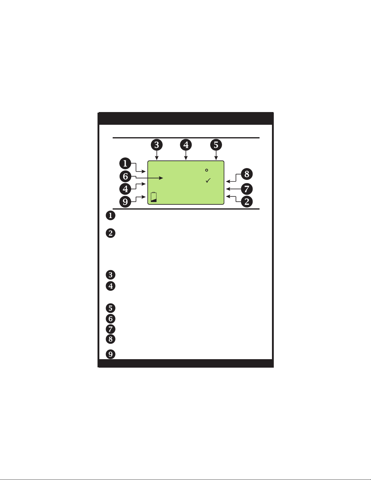
Display
Normal Operation
Manual Operation
Programmed Operation
Aux Heat
Clock Set
Time Period Programming
Overview
Weekday Programming
Weekend Programming
Advanced Setup
Advanced Features
Page #
Factory Defaults
Calibration
Battery Replacement
Warranty
Page 2
Page 3

OWNER'S MANUAL
Safety Warnings
T1045
P/N T1045
CAUTION
Follow Installation Instructions carefully.
DISCONNECT POWER TO THE HEATER AIR CONDITIONER BEFORE REMOVING
THE OLD THERMOSTAT AND INSTALLING
THE NEW THERMOSTAT.
WARNING
CAUTION
The two Alkaline “AA” batteries must be replaced at
least once every 12 months to ensure proper
operation. The Low Battery icon (fig. 1) will
appear on the display when it is time to replace
the batteries. If the thermostat is connected to
24v power, the batteries should still be installed, but
are not required.
When is displayed the batteries must be replaced
immediately. The manufacturer cannot be liable for
improper operation of the thermostat if the batteries are
not immediately replaced.
Annual battery replacement is especially critical in
locations subject to freezing temperatures. The
thermostat will be unable to turn on the heating system
if the batteries are exhausted.
FIG. 1
Page 3
Page 4

OWNER'S MANUAL
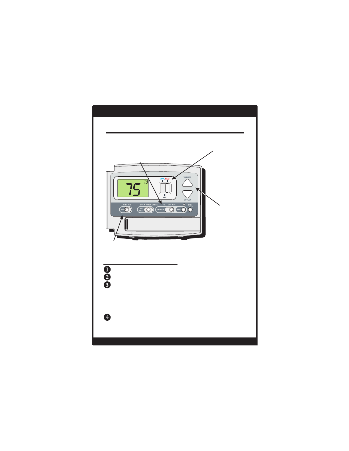
Location of Controls
T1045
AUX HEAT
SWITCH
Emergency
Normal
Lockout
DISPLAY
:
PM
I2:00
Su
FAN SWITCH
On or Auto
PROGRAM
SWITCH
RUN program
Program OFF
Set program
NEXT BUTTON
For programming
How to Use: The NEXT
button is used to advance from one step to
the next in the programming and advanced
setup screens (pgs 11-
19).
MODE SWITCH
Cool, Off or Heat
COOLER &
WA R M E R
BUTTONS
BI-COLOR LED
Heat or Cool demand
indicator when system
powered: Red = Heat
Green = Cool
RESET FILTER
How to Use: Press and
hold the RESET FILTER
butto n to clear the
FILTER
icon from the
display (pg 5). To adjust
when the icon
appears, see Advanced
Setup screens (pg 19).
FILTER
Page 4
Page 5
OWNER'S MANUAL
Display
AM
Morning
:
PM
I2:00
MTuWThF
SaSu
Day
Night
88
Day of the week. MTuWThF represent the five weekdays and SaSu represent the two weekend days.
Heat and Cool indicators.
In normal operation, Heat or Cool appears, depending
on the Mode Switch position. When heat or cool is
energized, the Heat or Cool indicator will flash. If the
thermostat is system powered the bi-color LED will
also illuminate (red for heating and green for cooling).
Clock Display.
Time period indicators. These indicate the part of
the program that is currently active, if the Program
Switch is positioned to RUN.
Evening
88
SET
FILTER
AUX
HEAT
COOL
T1045
Desired set temperature.
Current room temperature.
Indicates that 2nd stage of heat is energized.
Indicates when the filter should be serviced. Appears
after 0 - 1950 hours of blower operation (adjustable).
Indicates batteries need replacement.
Page 5
Page 6

OWNER'S MANUAL
Normal Operation
T1045
PROGRAM SWITCH
RUN program
MODE SWITCH
Cool, Off or Heat
Program OFF
SET program
:
PM
I2:00
Su
COOLER &
WA R M E R
BUTTONS
FAN SWITCH
On or Auto
Manual Operation (Program Switch OFF)
Select Cool or Heat with the Mode Switch.
Normally leave the fan switched to Auto.
In Fan Auto, the fan will turn on only with a heat
or cool demand. When Fan On is selected, the
fan will run continuously.
Adjust the desired set temperature with the
COOLER and WARMER buttons.
Page 6
Page 7
OWNER'S MANUAL
Normal Operation
T1045
PROGRAM SWITCH
RUN program
MODE SWITCH
Cool, Off or Heat
Program OFF
SET program
:
PM
I2:00
Su
SET
HEAT
COOLER &
WA R M E R
BUTTONS
FAN SWITCH
On or Auto
Programmed Operation
Select Cool or Heat with the Mode Switch.
Select RUN with the Program Switch.
Normally leave the fan switched to Auto.
In Fan Auto, the fan will turn on only with a heat
or cool demand. When Fan On is selected, the
fan will run continuously.
The desired set temperature may be temporarily
overridden. The thermostat will revert to the
programmed settings in the following time period.
Page 7
Page 8

OWNER'S MANUAL
T1045
Aux Heat
:
PM
I2:00
Su
Emergency - Disables all compressor
functions and energizes only Aux
Heat to satisfy the heat demand.
Normal - Aux Heat is allowed to run, if necessary,
along with the heat pump to satisfy the
heat demand.
SET
HEAT
AUX HEAT
SWITCH
Emergency
Normal
Lockout
Lockout - Aux Heat will never turn on
regardless of the heat demand.
When the Aux Heat switch is in the Emergency position the compressor
*
will also be locked out during cooling operation.
Page 8
Page 9

OWNER'S MANUAL
Clock Set
Slide the Program Switch to
the SET position.
Setting the time & day are the first two steps after
sliding the Program Switch to SET.
:
PM
Press NEXT
to advance
6:00
To slew the time more rapidly, push and hold the
COOLER or WARMER buttons.
Use these buttons to
adjust the current time.
T1045
Su
Use these buttons to
adjust the current day.
This thermostat is preprogrammed from the
factory to operate 1 or 2-Stage equipment without
the need for further programming. To optimize the
installation of this thermostat follow the instructions
in the Advanced Setup section.
Page 9
Page 10

OWNER'S MANUAL
Time Period Programming
Overview
PROGRAM SWITCH
Slide the Program Switch to the SET position.
The blinking icon(s) on the display may be
changed by pressing the COOLER or
WARMER buttons.
After the blinking icon is changed to the desired
selection, press the NEXT button.
Each item in the time period programming screens will flash
and can be modified with the COOLER & WARMER buttons.
Continue the steps above until programming is complete.
Slide the Program Switch to RUN and the thermostat
will run the time period programming.
If the Program Switch is in the OFF position, the thermostat
will not run the time period program. In this case, the
thermostat will be a manual heat or cool only thermostat.
T1045
Page 10
Page 11

OWNER'S MANUAL
Time Period Programming
Weekday Programming
Setting the time & day are the first two steps
after sliding the Program Switch to SET
(page 9).
T1045
Press NEXT
to advance
Press NEXT
to advance
Press NEXT
to advance
Press NEXT
to advance
AM
Morning
:
6:00
MTuWThF
AM
Morning
:
6:00
MTuWThF
AM
Morning
:
6:00
MTuWThF
AM
:
8:00
MTuWThF
Day
Next Page
8
SET
COOL
SET
HEAT
Page 11
Use these buttons to
adjust the start time for
the morning time period.
Use these buttons to
adjust the cool setpoint for
the morning time period.
Use these buttons to
adjust the heat setpoint for
the morning time period.
Use these buttons to
adjust the start time for
the day time period.
Page 12

OWNER'S MANUAL
Time Period Programming
Weekday Programming
T1045
Press NEXT
to advance
Press NEXT
to advance
Press NEXT
to advance
Press NEXT
to advance
AM
:
8:00
MTuWThF
Day
AM
:
8:00
MTuWThF
Day
:
PM
6:00
MTuWThF
:
PM
6:00
MTuWThF
Next Page
Evening
Evening
SET
COOL
SET
HEAT
SET
COOL
Use these buttons to
adjust the cool setpoint for
the day time period.
Use these buttons to
adjust the heat setpoint for
the day time period.
Use these buttons to
adjust the start time for
the evening time period.
Use these buttons to
adjust the cool setpoint for
the evening time period.
Page 12
Page 13

OWNER'S MANUAL
Time Period Programming
Weekday Programming
T1045
Press NEXT
to advance
Press NEXT
to advance
Press NEXT
to advance
Press NEXT
to advance
:
PM
6:00
MTuWThF
:
PM
I0:00
MTuWThF
Night
:
PM
I0:00
MTuWThF
Night
:
PM
I0:00
MTuWThF
Night
Next Page
Evening
SET
HEAT
SET
COOL
SET
HEAT
Use these buttons to
adjust the heat setpoint for
the evening time period.
Use these buttons to
adjust the start time for
the night time period.
Use these buttons to
adjust the cool setpoint for
the night time period.
Use these buttons to
adjust the heat setpoint for
the night time period.
Page 13
Page 14

OWNER'S MANUAL
Time Period Programming
Weekend Programming
AM
Morning
:
Press NEXT
to advance
Press NEXT
to advance
Press NEXT
to advance
Press NEXT
to advance
6:00
SaSu
:
6:00
SaSu
:
6:00
SaSu
8:00
SaSu
Day
Use these buttons to
adjust the start time for
the morning time period.
AM
Morning
SET
8
Use these buttons to
adjust the cool setpoint for
COOL
AM
Morning
SET
HEAT
AM
:
the morning time period.
Use these buttons to
adjust the heat setpoint for
the morning time period.
Use these buttons to
adjust the start time for
the day time period.
T1045
Next Page
Page 14
Page 15

OWNER'S MANUAL
Time Period Programming
Weekend Programming
AM
:
Press NEXT
to advance
Press NEXT
to advance
8:00
SaSu
Day
:
8 00
8:00
SaSu
SaSu
Day
SET
Use these buttons to
adjust the cool setpoint for
COOL
AM
AM
Day
62
SET
SET
the day time period.
Use these buttons to
adjust the heat setpoint for
HEAT
HEAT
the day time period.
T1045
Press NEXT
to advance
Press NEXT
to advance
:
PM
6:00
SaSu
:
PM
PM
6 00
6:00
SaSu
SaSu
Next Page
Evening
Evening
Evening
78
COOL
COOL
SET
SET
Page 15
Use these buttons to
adjust the start time for
the evening time period.
Use these buttons to
adjust the cool setpoint for
the evening time period.
Page 16

OWNER'S MANUAL
Time Period Programming
Weekend Programming
T1045
Press NEXT
to advance
Press NEXT
to advance
Press NEXT
to advance
Press NEXT
to advance
:
6:00
SaSu
:
I0:00
SaSu
Night
:
I0:00
SaSu
Night
:
I0:00
SaSu
Night
Evening
PM
SET
Use these buttons to
adjust the heat setpoint for
HEAT
PM
the evening time period.
Use these buttons to
adjust the start time for
the night time period.
PM
SET
Use these buttons to
adjust the cool setpoint for
COOL
PM
SET
the night time period.
Use these buttons to
adjust the heat setpoint for
HEAT
the night time period.
Page 16
Page 17

OWNER'S MANUAL
Time Period Programming
After you have completed setting the time
period programming, you have two options:
1) Run the time period program by sliding the
Program Switch to the RUN position.
Or,
2) Do not run the time period program. The
thermostat will operate as a manual heat
or cool thermostat. Slide the Program
Switch to OFF in this case.
T1045
Page 17
Page 18

OWNER'S MANUAL
T1045
Advanced Setup
This is normally done by the installer at initial installation.
Enter advanced setup by sliding the Program Switch to
SET. When the clock is flashing, press the NEXT button for
5 seconds. Do not release the button until this screen
appears.
Press NEXT
to advance
Press NEXT
to advance
Press NEXT
to advance
Press NEXT
to advance
Use these buttons to
adjust the deadband
from 1 to 6 degrees.
Use these buttons to
adjust the Cycles Per Hour
from 2 to 6.
d=no limit (zoning)
d1=d+no compressor
lockout (page 19).
Select backlight operation
when a button is pressed:
OFF: Never turns on.
2,4,6 or 8: Seconds back light will be on.
ON: Always on.*
Use these buttons to select
thermostat operation in
degrees C or F.
Continued
* ON is only available if the thermostat
is system powered.
Page 18
Page 19

OWNER'S MANUAL
Actual hours of
Press NEXT
to advance
0
fan operation
FILTER
Press RESET
FILTER
Press and hold the RESET
FILTER button to reset
the filter counter to 0 and
remove the icon
from the display.
0
SET
FILTER
Adjust the number of hours
the blower will run before the
icon appears on the
FILTER
display. 0 = off.
Slide the Program Switch to OFF or RUN to exit
Advanced Setup.
About Advanced
Features & Operation
:
PM
I2:00
Su
CYCLES PER HOUR - The Cycles Per Hour setting (page 18)
monitors the number of times per hour your HVAC unit may
energize. For example, at a setting of 6 cycles per hour the
HVAC unit will only be allowed to energize once every 10
minutes. The Cycles Per Hour limit may be temporarily
overridden by pressing the WARMER or COOLER button.
:
PM
I2:00
Su
TWO STAGE OPERATION - The 2nd stage of heat (auxiliary
heat) is turned on when the room temperature is equal to or
less than: the setpoint minus the 1st stage deadband (one
degree, adjustable), minus the 2nd stage deadband (two
degrees, non-adjustable).
2nd Stage
:
PM
I2:00
Su
FILTER FILTER
ICON - The icon will appear after a set
turn on
number of hours for fan run time (see above) has been
achieved. This counter keeps track of the number of hours
of fan run time whether the fan is energized in the heating
or cooling modes, or in stand alone operation.
Page 19
Heating
Deadband Deadband
(non-adj. 2 )
1st Stage
turn on
db 1db 2
(adj. 1-6 )
Heat or Cool
Setpoint
FILTER
Cooling
Deadband
db 1
(adj. 1-6 )
T1045
1st Stage
turn on
Page 20

OWNER'S MANUAL
CAUTION
T1045
Factory Default
If, for any reason, you desire to return all the stored settings
back to the factory default settings, follow the instructions below.
Enter advanced setup by sliding the Program Switch to
SET. When the clock is flashing, press the NEXT button for
5 seconds. Do not release the button until this screen
appears.
Press NEXT
to advance
When the Cycles Per Hour is
flashing, press and hold the NEXT
button until this screen appears.
AM
Morning
:
I2:00
MTuWThF
SaSu
Day
Night
88
Evening
PM
Press and hold the
88
NEXT button again
SET
FILTER
until this screen appears.
AUX
HEAT
COOL
AM
Morning
:
PM
I2:00
MTuWThF
SaSu
Day
Night
88
Evening
After restoring factory
88
defaults, the thermo-
SET
FILTER
stat screen will display
AUX
all icons.
HEAT
COOL
Slide the Program Switch to OFF or RUN
to return to normal operation.
WARNING: This will reset all Time Period and Advanced Programming to
the default settings. Any information entered prior to this reset may be
permanently lost.
Page 20
Page 20
Page 21

OWNER'S MANUAL
CAUTION
T1045
Calibration
Under normal circumstances it will not be necessary to adjust
the calibration of the temperature sensor. If calibration is
required, please contact a trained HVAC technician to
correctly perform the following procedure.
Enter advanced setup by sliding the Program Switch to
SET. When the clock is flashing, press the NEXT button for
5 seconds. Do not release the button until this screen
appears.
Press NEXT
to advance
When the Cycles Per Hour is
flashing, press and hold the NEXT
button until this screen appears.
Press NEXT
two times
to advance
Press NEXT
to store the
new value
AM
Morning
:
PM
I2:00
MTuWThF
SaSu
Day
Night
88
Evening
88
SET
FILTER
AUX
HEAT
COOL
Press the NEXT button twice
to advance to the calibration
screen.
Adj ust the tempe ratu re
reading using the WARMER
and COOLER buttons, then
press the NEXT button to
store the new value.
Slide the Program Switch to OFF or RUN
to return to normal operation.
Page 21
Page 22

OWNER'S MANUAL
Battery Replacement
Battery Replacement
The batteries are easily accessible from the battery
slot located on the front of the thermostat (fig. 1). To
open the battery slot, press down on the battery
cover (fig. 1) and pull out (fig. 2).
:
PM
I2:00
Su
T1045
Pull out
Press
down
FIG. 1 FIG. 2
Battery
slot
(Bottom View)
Remove the old batteries and replace with the new
AA alkaline batteries (fig. 3).
New
batteries
in
Old
batteries
out
Place the bottom hook of the battery cover into the
slot and snap closed (fig. 4).
Snap closed
The batteries must be replaced
immediately when the thermostat
displays the low battery icon (fig.
1). If the thermostat is connected
(Bottom View)
to 24v power, the batteries should
still be installed. Installing the batteries when
system powered (24VAC) will keep the clock
running in the event of line power interruption.
Page 22
Bottom
Hook
FIG. 4
FIG. 1
Page 23

OWNER'S MANUAL
T1045
Warranty
One-Year Warranty - This Product is warranted to be free from defects in material and
workmanship. If it appears within one year from the date of original installation, whether or not
actual use begins on that date, that the product does not meet this warranty, a new or
remanufactured part, at the manufacturer’s sole option to replace any defective part, will be
provided without charge for the part itself provided the defective part is returned to the distributor
through a qualified servicing dealer.
THIS WARRANTY DOES NOT INCLUDE LABOR OR OTHER COSTS incurred for diagnosing, repairing,
removing, installing, shipping, servicing or handling of either defective parts or replacement
parts. Such costs may be covered by a separate warranty provided by the installer.
THIS WARRANTY APPLIES ONLY TO PRODUCTS IN THEIR ORIGINAL INSTALLATION LOCATION AND
BECOMES VOID UPON REINSTALLATION.
LIMITATIONS OF WARRANTIES – ALL IMPLIED WARRANTIES (INCLUDING IMPLIED WARRANTIES OF
FITNESS FOR A PARTICULAR PURPOSE AND MERCHANTABILITY) ARE HEREBY LIMITED IN DURATION TO
THE PERIOD FOR WHICH THE LIMITED WARRANTY IS GIVEN. SOME STATES DO NOT ALLOW LIMITATIONS
ON HOW LONG AN IMPLIED WARRANTY LASTS, SO THE ABOVE MAY NOT APPLY TO YOU. THE
EXPRESSED WARRANTIES MADE IN THIS WARRANTY ARE EXCLUSIVE AND MAY NOT BE ALTERED,
ENLARGED, OR CHANGED BY ANY DISTRIBUTOR, DEALER, OR OTHER PERSON WHATSOEVER. ALL
WORK UNDER THE TERMS OF THIS WARRANTY SHALL BE PERFORMED DURING NORMAL WORKING
HOURS. ALL REPLACEMENT PARTS, WHETHER NEW OR REMANUFACTURED, ASSUME AS THEIR
WARRANTY PERIOD ONLY THE REMAINING TIME PERIOD OF THIS WARRANTY.
1. Normal maintenance as outlined in the installation and servicing instructions or owner’s
manual, including filter cleaning and/or replacement and lubrication.
2. Damage or repairs required as a consequence of faulty installation, misapplication,
abuse, improper servicing, unauthorized alteration or improper operation.
3. Failure to start due to voltage conditions, blown fuses, open circuit breakers or other
damages due to the inadequacy or interruption of electrical service.
4. Damage as a result of floods, winds, fires, lightning, accidents, corrosive environments or
other conditions beyond the control of the Manufacturer.
5. Parts not supplied or designated by the Manufacturer, or damages resulting from their use.
6. Manufacturer products installed outside the continental U.S.A., Alaska, Hawaii, and
Canada.
7. Electricity or fuel costs or increases in electricity or fuel costs for any reason whatsoever
including additional or unusual use of supplemental electric heat.
8. ANY SPECIAL INDIRECT OR CONSEQUENTIAL PROPERTY OR COMMERCIAL DAMAGE OF ANY
NATURE WHATSOEVER. Some states do not allow the exclusion of incidental or
consequential damages, so the above may not apply to you.
This warranty gives you specific legal rights and you may also have other rights which may
vary from state to state.
THE MANUFACTURER WILL NOT BE RESPONSIBLE FOR:
Page 23
Page 24

Programming Worksheet see page 10
DAY
Monday
Tuesday
Wednesday
Thursday
Friday
Saturday
Sunday
PERIOD
Morning
Day
Evening
Night
Morning
Day
Evening
Night
START TIME
COOL
HEAT
Printed on recycled paper.
P/N 88-636 Rev. 3
 Loading...