

Page 1
WIRELESS REMOTE SENSOR
THE WIRELESS REMOTE SENSOR SYSTEM IS MADE UP OF ONE RECEIVER AND AT LEAST ONE
WIRELESS SENSOR.
Up to 8 Wireless Sensors may be used with 1 Receiver (Unit ID# 0 - 7).
The Receiver automatically averages the temperatures from up to 8
Wireless Sensors on the same House Code and reports the average to
the thermostat.
The Receiver will only ‘listen’ to Wireless Sensors with the same House
Code as the Receiver, and will ‘ignore’ sensors with different House
Codes than the Receiver.
If more than 1 Wireless Sensor is used with 1 Receiver, then all Sensors
and the Receiver must have the same House Code for proper operation.
If more than 1 Wireless Sensor is used with 1 Receiver, then each
Sensor must have a different Unit ID.
SUGGESTED USES FOR ONE WIRELESS REMOTE SENSOR:
To report the outdoor temperature when using a compatible residential
thermostat. It is recommended to attach the Wireless Sensor to a north-
facing wall where it will not be in direct sunlight or the spray of sprinklers.
To report the temperature of a room, such as that of a baby’s room when
using a compatible residential thermostat.
To control to or read to the temperature at the return duct when using a
compatible commercial thermostat.
To control the temperature in a space that is different from where a
compatible commercial thermostat is located.
SUGGESTED USES FOR MULTIPLE WIRELESS REMOTE SENSORS:
To control to the average of multiple Wireless Sensors in a large open
space using a compatible Commercial thermostat. This type of
application would include large, open office areas.
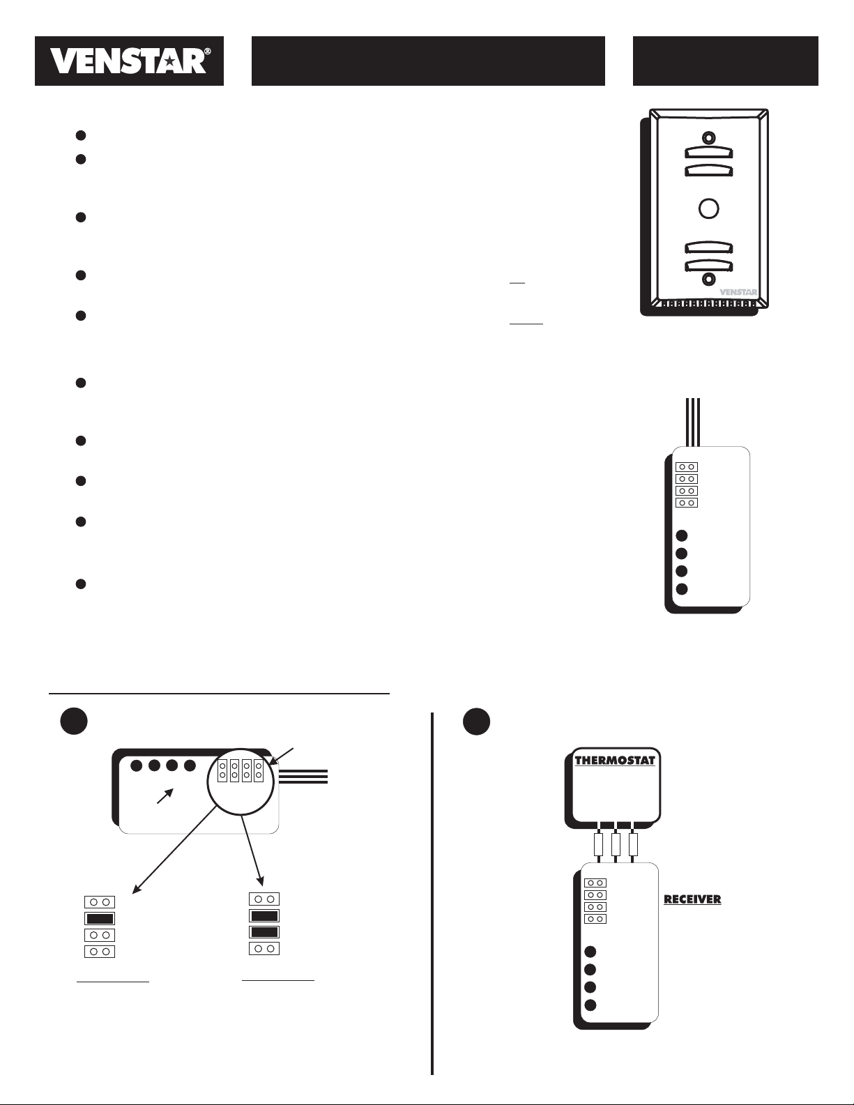
MODEL
ACC0414REC
WIRELESS REMOTE SENSOR
with Override button
MODEL ACC0414RF
HC1
HC2
HC4
HC8
0
12
3
RECEIVER
MODEL ACC0414REC
Receiver Setup & Installation
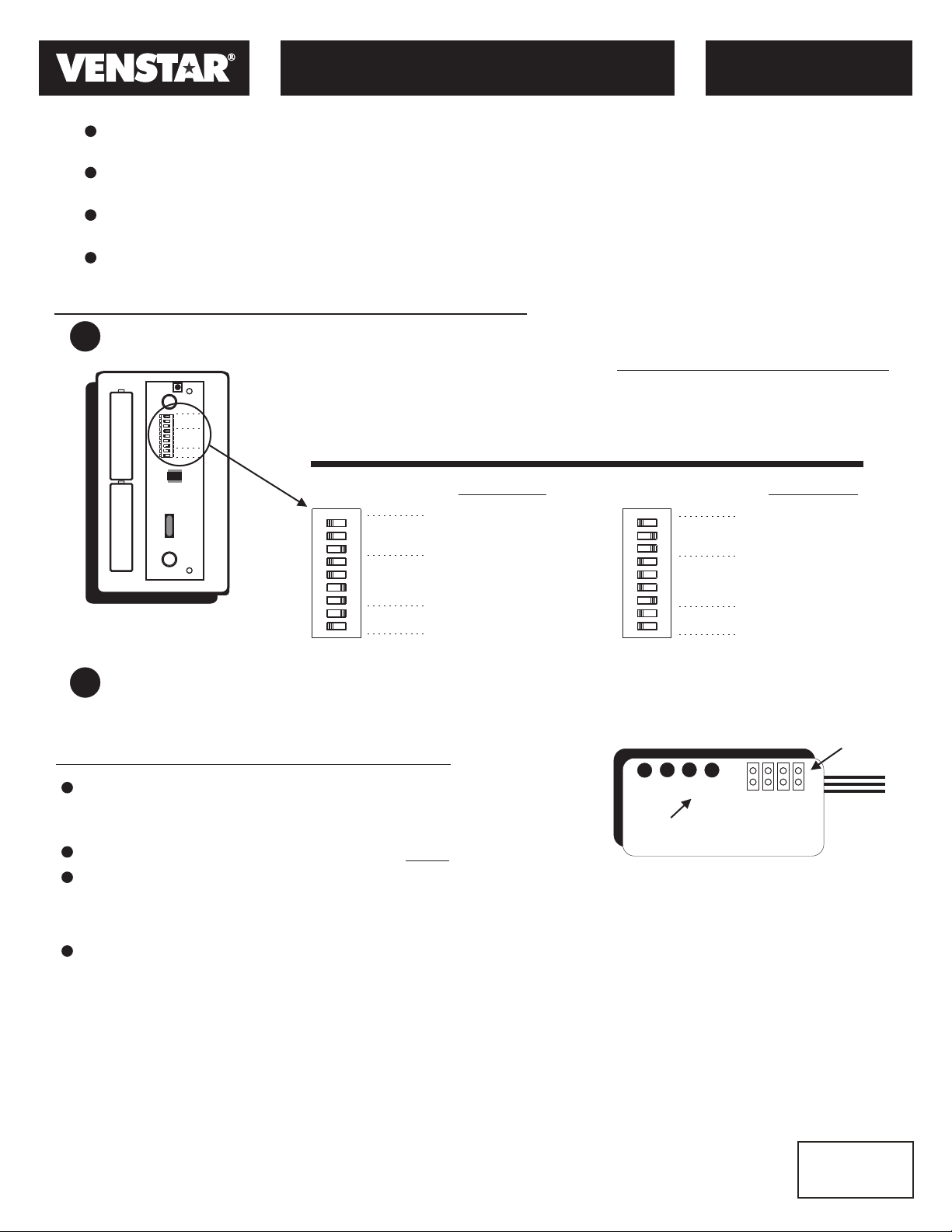
Set the House Code jumpers on the Receiver
1
Jumper
Location
3
LED’s
A B
HC1
HC2
HC4
HC8
Example A
House Code
ID = 2
©Venstar Inc. 05/08 - Patent Pending
0
12
HC1
HC2
HC4
HC8
HC1
HC2
HC4
HC8
Example B
House Code
ID = 6
(2 + 4 = 6)
Connect the Receiver to the thermostat
2
The Receiver is
put inside the
wall behind the
thermostat.
RS GND
RS+5
RS*
BLACK
WHITE
RED
HC1
HC2
HC4
HC8
0
12
3
*Consult your thermostat
installation manual for
the correct name of this
terminal.
P/N 88-793 Rev. 1
Page 2
WIRELESS REMOTE SENSOR
THE WIRELESS SENSOR CAN TRANSMIT THE TEMPERATURE IN ONE OF FOUR SELECTABLE TIME INTERVALS:
Every 10 Seconds – This setting is most useful for Indoor Remote Sensor applications where fast
response is needed; such as Remote Duct or Room Sensor applications.
Every 2 Minutes – This setting is used for Indoor Remote Sensor applications where a moderately
fast response is needed; such as Remote Duct or Room Sensor applications.
Every 5 Minutes – This setting is also used for Indoor Remote Sensor applications under normal
circumstances. At this setting battery life expectancy is approximately 3 years.
Every 10 Minutes – This setting is used for Outdoor Temperature reading. With this setting battery life
expectancy is at its longest.
Wireless Sensor Setup & Installation
Set the switches on the Wireless Sensor
1
All switches in the OFF position = 0.
ADD all switches in the ON position
ON
OFF
4
Unit
2
ID
1
8
4
House
2
Code
1
2
Tx
1
Interval
to arrive at the proper setting.
The House Code must match the
House Code setting on the Receiver.
Transmission Interval (Tx Interval)
0 = 10 Seconds
1 = 2 Minutes
2 = 5 Minutes
3 = 10 Minutes
MODEL
ACC0414RF
WIRELESS REMOTE SENSOR
Switch Location
Attach the Wireless Remote Sensor to the Wall.
2
A B
OFF
ON
4
Unit
2
Code
1
8
House
4
2
Code
1
2
Tx Rate
1
Example A
Unit
ID = 1
House
Code = 3
(1+2 = 3)
Tx
Interval = 5 min.
(2)
OF
ON
F
4
2
Code
1
8
House
4
2
Code
1
2
Tx Rate
1
Unit
Example B
Unit
ID = 3
(1 + 2 = 3)
House
Code = 1
Tx
Interval = 10 sec.
(0)
Use the supplied screws to secure the Wireless Sensor to the wall.
Care must be taken when installing on to a J-Box to avoid drafts from behind the Sensor.
Jumper
Troubleshooting & Diagnostics
The temperature range of the Wireless Sensor is 32° to 127°
3
0
2
1
HC1
HC2
HC4
HC8
Location
Fahrenheit. For low temperature applications AA lithium batteries
will extend the temperature range to -10° to 127° Fahrenheit.
LED’s
Make sure the Receiver & Sensor use the same House Code #.
The Receiver has 4 LEDs. The LEDs correspond to Unit ID# 0 - 3.
When the Receiver receives a valid temperature from a Wireless Sensor, the corresponding LED will blink
and stay on until the next valid transmission. If a valid transmission is not received within 15 minutes, the
LED will turn off.
The Receiver can receive and average up to 8 different Unit ID’s on the same House Code, but the LEDs
will only indicate the first 4, (#0 - 3). The LEDs are included as a diagnostic tool to confirm reception.
This equipment has been tested and found to comply with the limits for a class B digital device, pursuant to part 15 of the FCC Rules. These limits are designed
to provide reasonable protection against harmful interference in a residential installation. This equipment generates, uses and can radiate radio frequency
energy and if not installed and used in accordance with the instructions, may cause harmful interference to radio communications. However, there is no
guarantee that interference will not occur in a particular installation. If this equipment does cause harmful interference to radio or television reception, which can
be determined by turning the equipment off and on, the user is encouraged to try to correct the interference by one or more of the following measures:
* Reorient or relocate the receiving antenna.
* Increase the separation between the equipment and receiver.
* Connect the equipment into an outlet on a circuit different from that to which the receiver is connected.
* Consult the dealer or an experienced radio/TV technician for help.
This equipment has been verified to comply with the limits for a class B computing device, pursuant to FCC Rules. Operation with non-approved equipment is
likely to result in interference to radio and TV reception.
The user is cautioned that changes and modifications made to the equipment without the approval of manufacturer could void the user's
authority to operate this equipment.
©Venstar Inc. 05/08 - Patent Pending
FCC STATEMENT
P/N 88-793 Rev. 1
RF Sensor
c
ACC0414RF
C
F
FCC ID MUHRSTX2
 Loading...