

Page 1
Installation Instructions
TSTATCCPB501
TSTATBBPB501
P474-1050
Digital Thermostat
I,IOTE; Re_ i_ ¢*_-e Irmi_(_ _ h_ore sm_l_ _ inst_W_
00o_A
HEAT
COOL
&
HEAT
PUMP
MULTI-STAGE• PROGRAMMABLE
F;:r;,_:li_TSTAT.t G C.Ir_ell: _ _11U $_ _ h_ 13TS-TA42
Page 2
PREPARATION 2
REMOVE OLD THERMOSTAT 3
INSTALL BACKPLATE & WIRE 4
WIRING DIAGRAMS 5
CALIBRATION 8
TEST OPERATION 9
TROUBLESHOOTING 10
CAUTION FollowInstollofior_InstrL_tior_carefully.
DISCONNECT POWER TO THE HEATER - ./_
AIRCONDmONER BEFORE REMOVING
THE OLD THERMOSTAT AND INSTALLING
THENEW 1HERMOSTAT. WARNING
Replacement Components Division _) Carrier Corporation 4/01
This device complies with Part 15 of the FCC rules.
Operation is subject to the following 2 conditions:
(1) This device may not cause harmful interference,
and (2) This device must accept any interference
received, including interference that may cause
undesired operation.
Page I
Page 3
©
©
©
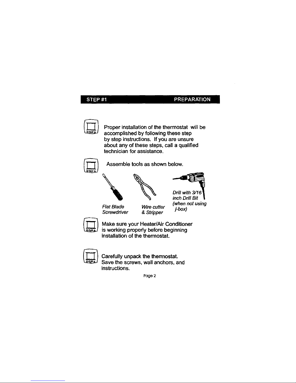
Proper installation of the thermostat will be
accomplished by following these step
by step instructions. If you are unsure
about any of these steps, call a qualified
technician for assistance.
Assemble tools as shown below.
(when not using
Flat Blade Wire cutter j-box)
Screwdriver & Stripper
Make sure your Heater/Air Conditioner
is working propedy before beginning
installation of the thermostat.
©
Carefully unpack the thermostat.
Save the screws, wall anchors, and
instructions.
Page 2
Page 4
©
©
©
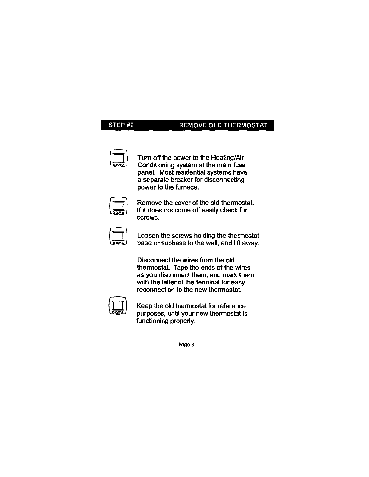
Turn off the power to the Heating/Air
Conditioning system at the main fuse
panel. Most residential systems have
a separate breaker for disconnecting
power to the furnace.
Remove the cover of the old thermostat.
If it does not come off easily check for
screws.
Loosen the screws holding the thermostat
base or subbase to the wall, and lift away.
©
Disconnect the wires from the old
thermostat. Tape the ends of the wires
as you disconnect them, and mark them
with the letter of the terminal for easy
reconnection to the new thermostat.
Keep the old thermostat for reference
purposes, until your new thermostat is
functioning properly.
Poge3
Page 5

©
@
Remove the backplate connector from the
rear of the thermostat. Installwires as directed
below. When finished, snap thermostat on to
backplate.
If the terminal designations on your old
thermostat do not match those on the
new thermostat, refer to the chart below,
or the wiring diagrams that follow.
Wire from the
old thermostat
Function
Install on the
new thermostat
terminal marked
GorF
YI.YorC
W1,Wor H
Rh. R, M, Vr.A
C
O/B
Y2
W2
RS+5
RS
RS G
CKI
CK2
Fan
Cooling
Heating
Power
Common
Re'/. Valve
2nd Stage Cool
2nd Stage Heat
RemoteSensor+5vd¢
ReooteSenso¢Signal
_note SensorGco_m
D_/_ S_etch1
OntContactS*_ch2
connector marked
G
Y1
W1,0,B
R
C*
Wl ,O,B**
Y2
W2
* C may not be used on all systems.
** O/B is used if your system is a Heat Pump.
Poge 4
Page 6

5 Wire, 1 Stage Cooling, t Stage Gas Heat
Resident;alGas orElectroHeat *,
O
II
24 va¢ common
fan relay
com0ressor relay
1st staae heat circuit
24 yac rehJm
* ff u_ing e_ctric heat this option must be
sek_cted on during advanced setup.
L
E
>-<1
C
G
>-<1
Y1
>,,<1
O
w1
R
Y2
>'-<'l
)IW2
4 Wire, 1 Stage Cooling, 1 Stage Gas Heat
O
]
Res_entiw Gasor ElectricHeat*,
ElectricCool, splitsystems&pac_Jage
units
fan r_lay
compressor relay
1st stan_ heat _r_uff
24 vac retum
*if usingelectricheatthis optionmustbe
selectedon duringadvancedsetup.
Page 5
L
E
C
G
Y1
O
N1
R
_2
V2
Page 7

6Wire,2StageCooling,1StageHeat
Residential2StageCooling,with
0 Gasor ElectricHeat"
11
L
>-<1
E
24 rag common >_l
C
f_n mlsv >'<J
- G
_omoressor mlav _<
Y1
0
staae heat circuit >_lwl
1st
24 V_ return >-<i R
2nd staqe compressor relay x i y2
* ffusing electric heat, this option must W2
be se_Jed during advanced Setup. _J
ii
6 Wire, 1 Stage Cooling, 2 Stage Heat
O
w2 Y2 R Wl Y1 G C
bl
Residential & comrnem_l 1 Stage Cooling,
with 2 Stage Gas ot _ Heaff
Thermostat
24 vac common
fan relay
_omDrP_sor relav
1st staae heat circuit
24 van return
>-.<
>-<
2nd =t_n_ hP-nt PJrrJJff
_6
L
E
C
G
Y1
0
Wl
R
Y2
Page 8

7Wire.2StageCooling,2StageHeatCommercialGasorF_-'tdcHeat_,
Be¢_ Cod, splitsystems& package ur_ts
Y2
O
Wl Y1 G C
[I
- Comme_hd hut num_ _not have
indudJng Commerce[ Heat pomps"
24 vac common
fan relay
comDreSSQr re_av
1st stage heat drcuit
24 vac return
2nd staqe compressor relay
2nd stone heat PJ_JJit
-- Ku_inge_c paat,_s opt_ must
tl_.heatpumptumed on in advanced_ebJp. be _el_ted o_du_ng_vat_ad ee_
5 Wire, 1 Stage Cooling, 1 _tage Heat - Heat Pump"
0
"ffu_ngm_c/_ heet pump, tt_ op_on
mustbe _elected_ dunngaovancede_up.
m
L
>'<IE
X
C
>_
G
Y1
>._
O
Wl
R
Y2
W2
.J
No a_0dliafyheat, residentialHeat Pumps.
spit systems& pad_ageunits
Thermostat
ii
24 vac common
fan relay G
cornoressorrelav
reversina valve YOf
24 va_ return
,__v2
Page 9

6 Wire, 1 Stage Cooling, 2 Stage Heat, Heat Pump *
0 Most reside_aJ split _md package heat pumps
W2 _r2 W,1 YI G with_Jxil_ar/heat
24 v_c common ><
f_n relay I
>..<
comeressor relay >'<
1st staae heat circuit >'<
>-<
24 vac return >'<
>_
• The heatpumpoptionmustbeselected
on durtugadvancedsetup.
L
E
C
G
Y1
0
N1
R
_2
V2
Every thermostat is calibrated before it leaves the factory.
Under normal circumstances there will never be a need to
recatibrate the thermostat again.
To accommodate specialneeds, the thermostat may be recalibrated
following these steps:
1. While holding the mode button in, press the down button for
2 seconds. After allthe icons in the display appear, release
the buttons,
2. Press the mode button.
3. Press the up or down buttons until the flashing number
equals the current room temperature.
4, Press the mode button to return to normal operation.
Poge8
Page 10

(_ urn the power on to the Heating/Air
Conditioning system.
©
Press the MODE button repeatedly until
the HEAT icon appears on the display.
Press the Up or Down buttons until the set
temperature is 10 degrees above room
temperature. The furnace should turn on.
©
Press the MODE button repeatedly until
the COOL icon appears on the display.
Press the Up or Down buttons until the set
temperature is 10 degrees below room
temperature. The air conditioner should
turn on. NOTE: Most equipment has a
time delay of 5 minutes between cool
cycles. This feature is defeatable on the
thermostat. Consult the Owner's Manual
under Setup, cycles per hour.
(_ ress the MODE button to OFF. Press
the FAN button to Fan On, The fan
should turn on and run continuously.
Poge 9
Page 11

©
©
©
_SYMPTOM: When using 4 wires (R, G, W, Y),
the air conditioning or heat equipment tries
repeatedly to turn on, but cannot. At
times the display dims or disappears.
CAUSE: There is not enough power available
to "power share".
REMEDY: Connect a 270 ohm, 10 watt power
resistor at the furnace as shown below.
For ProblemAJC ForProblemHeat
SYMPTOM: The air conditioning does not
attempt to turn on.
CAUSE: The compressor timer lockout may
prevent the air conditioner from
turning on, for a period of time.
REMEDY: Consult the Owner's Manual in
the Setup section to defeat the
cycles per hour and compressor
timeguard.
SYMPTOM: The display is blank.
CAUSE: Lack of proper power.
REMEDY: Make sure power is turned on to
the furnace and that you have 24vac
between R & W. IfC is used, 24vac
between R & C,
Poge lO
Page 12

©
©
SYMPTOM: The air conditioning does not
attempt to turn on.
The cooling setpoint is set too
high.
REMEDY: Consultthe Owner's Manual in
the Setup section to lower the
cooling setpoint limit.
SYMPTOM: The heating does not attempt
to turn on.
CAUSE: The heating setpoint is set too
low.
REMEDY: Consult the Owner's Manual in
the Setup section to raise the
heating setpoint limit.
Page 11
Page 13

@
SYMPTOM: When controlling a residential heat
pump, and asking for cooling, the heat
comes on.
CAUSE: Heat pump is not selected "on" inthe
Advanced Setup.
REMEDY: Select heat pump on during Advanced
Setup programming. Consult the Owner's
Manual.
@
SYMPTOM: When calling for cooling, both
the heat and cool come on.
_C_AUSE:The Advanced Setup is configured
to control a heat pump, and the hvac
the thermostat iscontrolling isa
"conventional" (non heat pump)
system.
REMEDY: Consult the Owner's Manual in
the Advanced Setup section to turn
off the heat pump.
_TAR TSTATCCPl_501
P474-1_
_h FCC Standa_
FOR HOME O_ OFFICE U_
4Z95
PIN 88-335
Poge 12
 Loading...