

Page 1
SPBS8
• PARKING SENSOR SYSTEM
• PARKEERHULP
• SYSTÈME D'AIDE AU STATIONNEMENT
• RADAR DE APARCAMIENTO
• RÜCKFAHRWARNSYSTEM
USER MANUAL 2
GEBRUIKERSHANDLEIDING 9
NOTICE D’EMPLOI 16
MANUAL DEL USUARIO 23
BEDIENUNGSANLEITUNG 30
Page 2
SPBS8
USER MANUAL
1. Introduction
To all residents of the European Union
Important environmental information about this product
This symbol on the device or the package indicates that disposal of the device after its
lifecycle could harm the environment. Do not dispose of the unit (or batteries) as unsorted
municipal waste; it should be taken to a specialized company for recycling. This device
should be returned to your distributor or to a local recycling service. Respect the local
environmental rules.
If in doubt, contact your local waste disposal authorities.
Thank you for choosing Velleman! Please read the manual thoroughly before bringing this device into
service. If the device was damaged in transit, do not install or use it and contact your dealer. Damage
caused by disregard of certain guidelines in this manual is not covered by the warranty and the
dealer will not accept responsibility for any ensuing defects or problems.
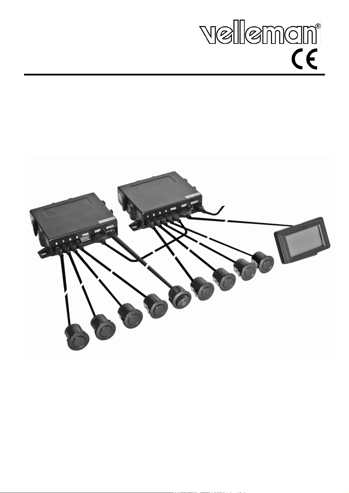
The SPBS8 car parking sensor system is a smart safety aid device that is an integration of
functional piezo-ceramic, ultrasonic, electronic, computer data processing and other technologies.
Incorporating the principle of ultrasonic distance measurement and the technology of fuzzy
processing of computer data, it correctly detects obstacles behind and/or in front of the vehicle and
warns the driver with clear audio and/or visual signals, thus protecting the vehicle against bumping
into the obstacles.
2. Safety Instructions
Keep the device away from children and unauthorised
users.
Indoor use only.
Keep the controller units and cabling away from rain,
• Damage caused by disregard of certain guidelines in this manual is not covered by the warranty and
the dealer will not accept responsibility for any ensuing defects or problems.
• Note that damage caused by user modifications to the device is not covered by the warranty.
moisture, splashing and dripping liquids.
Risk of electroshock during installation.
3. General Guidelines
• Protect this device from shocks and abuse. Avoid brute force when operating the device.
• Protected the device against extreme heat, dust and moisture.
• Familiarise yourself with the functions of the device before actually using it.
• All modifications of the device are forbidden for safety reasons.
• Only use the device for its intended purpose. Using the device in an unauthorised way will void the
warranty.
4. Features
• parking aid system with front and rear obstacle detection
• visible and audible warning
• 4 front and 4 rear ultrasonic sensors
• 2 Electronic Control Units (ECU) for independent front and rear detection
• sensor malfunction indication
• obstacle direction indication
• 3 zones detection: safety, caution and danger
01 (09/10/2008) Velleman®
2
Page 3
SPBS8
Box includes
• 1 LCD display with mounting stand and cable
• 1 front controller unit
• 1 rear controller unit
• 8 sensors
• 4 front sensor cables of 4,5m each, numbered 5~8
• 4 rear sensor cables of 2,5m each, numbered 1~4
• 1 on/off switch with cabling (2,4m)
• 1 power cable for rear ECU
• 1 cable to connect front and rear ECU
• 1 drill Ø18,5mm for sensor mounting
• 1 user manual
• Cable clips
• Double sided adhesive tape
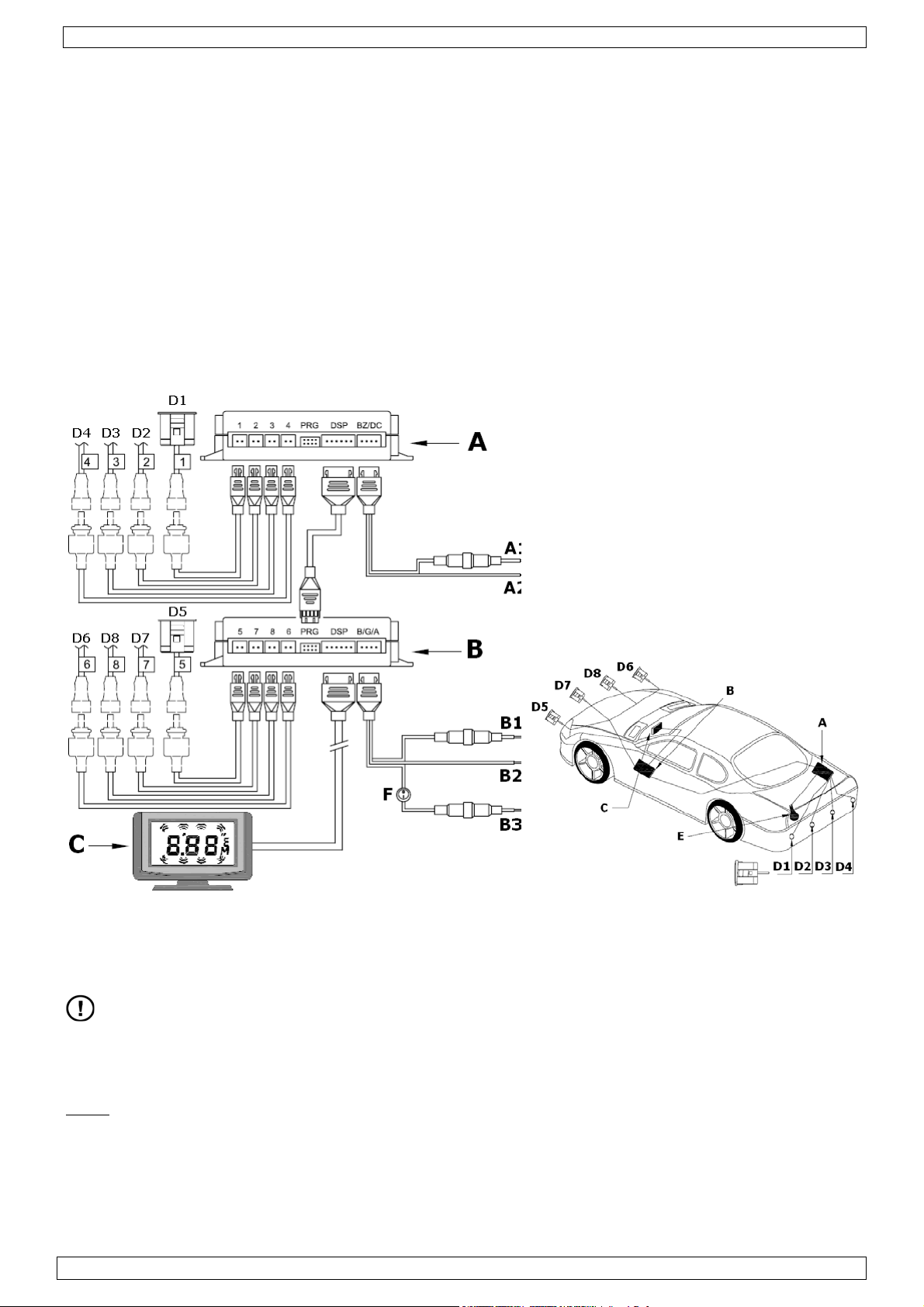
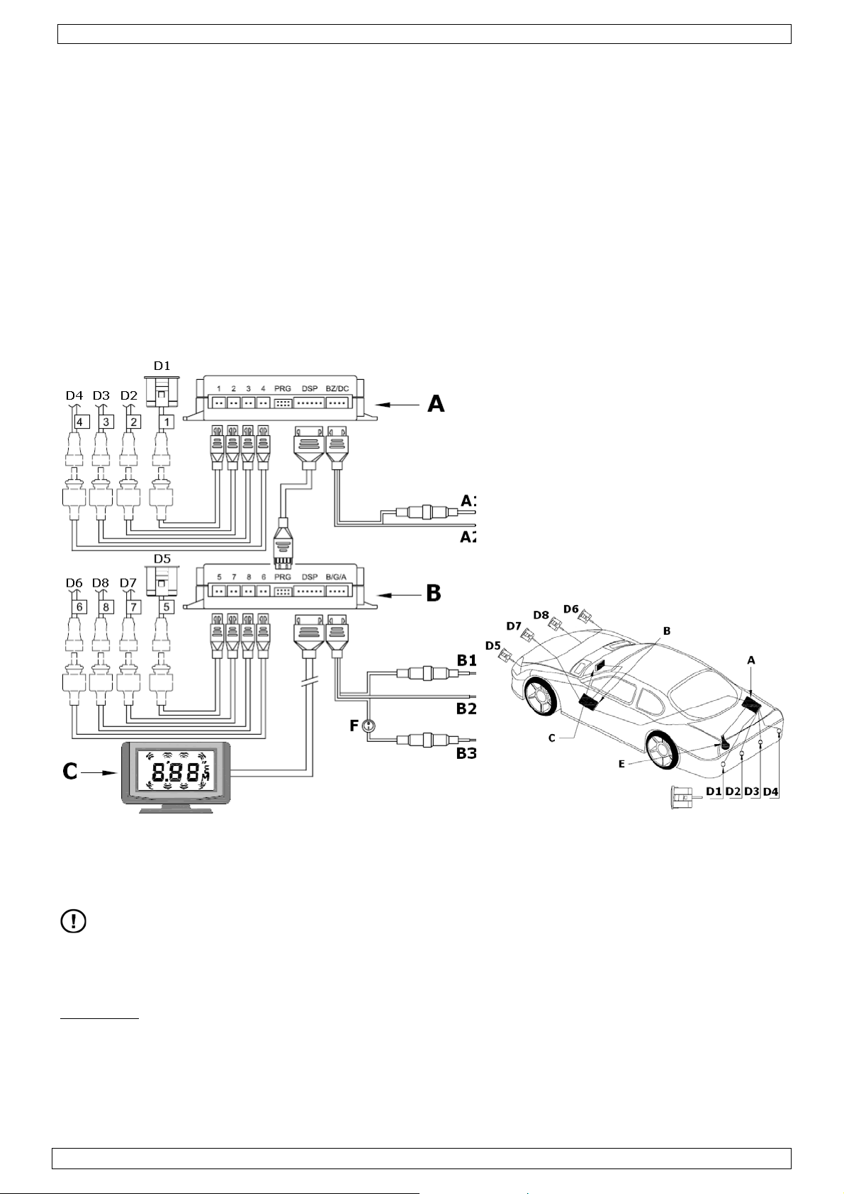
5. System overview
A. Rear Electronic Control Unit
A1. DC +12V (from reverse light)
A2. GND
B. Front Electronic Control Unit
B1. ACC +12V
B2. GND
B3. DC +12V (from brake light)
C. Display unit
D1~D8. Sensor
E. Reverse light
F. On/Off switch
6. Installation
DO NOT apply power to the system before all connections are made.
Sensors
• Choose the location of the sensors on the bumper carefully, as the proper functioning of the
system depends on it.
beware that detection results might be affected when sensors are installed in steel bumpers.
Note:
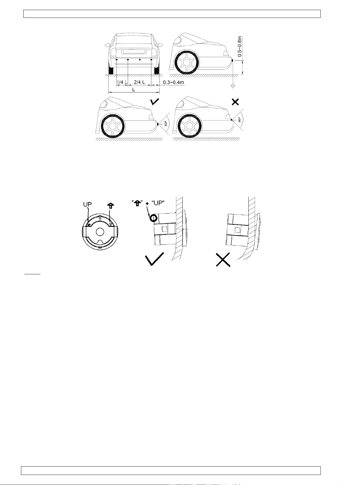
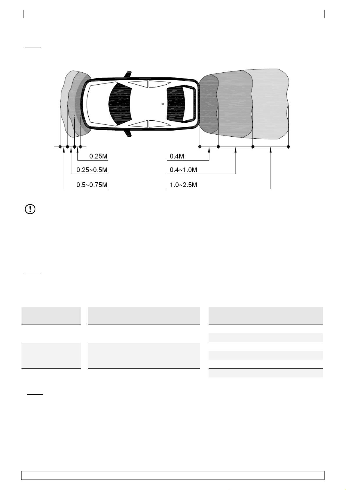
• Refer to the picture below for the best horizontal and vertical position. L=width of the vehicle.
01 (09/10/2008) Velleman®
3
Page 4
SPBS8
• Also make sure no part of the bumper is blocking the view of the sensor.
• Mark the location of the holes on the bumper and drill the holes with the included hole saw
(Ø18.5mm).
• Remove all burrs from the edge of the holes.
• Insert the sensors and cables in the holes. All sensors are identical. Make sure the central axis of
the sensor is perpendicular to the bumper surface and the ‘UP’ indication is facing upwards (see
image below).
Note: The sensors can be repainted to match the colour of the bumper. However, the thickness of
the paint layer may not exceed 0.1mm!
Electronic Control Units (ECU)
• See image under paragraph ‘system overview’ for an outline on where to install the different
parts of the system. The rear ECU should be installed in the trunk close to the reverse light
cabling, while the front ECU should be installed close to the fuse box inside the car.
• Refer to the vehicle installation drawings or experienced advice when determining the location of
the control units. The control units should not be close to potential sources of interference, e.g.
cable bundles, exhaust pipe….
• Make sure the power cables of the control units are easily accessible.
• Be careful not to damage any cabling or other vital parts of the car when screwing the control
units in place.
Display unit
• The display unit should be mounted on the dashboard with the included mounting bracket. Make
sure that the display is readable under all conditions.
Cabling/connections
• See image under paragraph ‘system overview’ for the location of the sensors. The numbering is
very important as it determines the proper functioning of the system.
• Every sensor cable has a number written on it. Make sure that the right cable is used for every
sensor. E.g. sensor 5 (front-left) must be connected with cable number 5 to port 5 of the front
ECU.
• Insert the plug of the cable into the socket of the sensor and secure the connection by screwing
the cap over the socket.
• Connect the other side of the cable to the corresponding port on the ECU.
01 (09/10/2008) Velleman®
4
Page 5
SPBS8
Connecting power rear ECU
• The rear ECU gets power from the reverse light circuit of the vehicle. Use the red/black rear ECU
power cable with the 2-pin connector and the included cable clips to make the connections.
• Locate the +12V power cable of the reverse light circuit and guide it through a cable clip.
• Insert the red cable of the rear ECU power cable in that cable clip and press the metal part of the
clip tightly. Close the cable clip.
• Locate the GND cable of the reverse light circuit and guide it through a cable clip.
• Insert the black cable of the rear ECU power cable in that cable clip and press the metal part of
the clip tightly. Close the cable clip.
• Connect the power cable to the rear ECU.
Connecting power front ECU
• The front ECU gets power from the ACC power. A signal from the brake light circuit will activate
the system. Use the included orange/brown/black front ECU power cable with the 4-pin
connector and the included cable clips to make the connections.
• The front ECU power cable contains an On/Off switch (F), which enables the user to switch the
system off (e.g. during traffic jam).
• Install the On/Off switch (F) in an easy accessible location on the dashboard. The included hole
saw can be used to drill the hole. Be careful not to damage any cabling or other vital parts of the
car when drilling.
• Locate the +12V power cable of the brake light circuit and guide it through a cable clip.
• Insert the (brown) cable marked with ‘B’ in that cable clip and press the metal part of the clip
tightly. Close the cable clip.
• Locate an ACC cable (e.g. from car radio) and guide it through a cable clip.
• Insert the (orange) cable marked with ‘ACC’ in that cable clip and press the metal part of the clip
tightly. Close the cable clip.
• Locate the GND cable of the brake light circuit and guide it through a cable clip.
• Insert the black cable of the front ECU power cable in that cable clip and press the metal part of
the clip tightly. Close the cable clip.
• Connect the power cable to the front ECU.
7. Operation
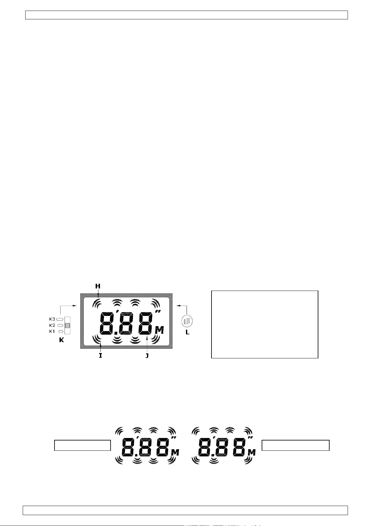
Display overview
H. Front direction indication
I. Rear direction indication
J. Distance in m (large digits)
K. Volume switch (on back)
K1. Low
K2. Middle
K3. High
L. Sound hole (on back)
Start-up
• Make sure the power On/Off switch (F) is in the on position.
• When reverse gear is engaged, the system will beep once (0.5 seconds) to indicate diagnostics
mode started. Both rear and front sensors start working.
• When a failure is detected, the display will show the letter ‘E’ followed by the ID of the faulty
sensor(s) for about 3 seconds. E.g. when sensor number 3 is defective, the display will show
‘E3’. After 3 seconds, the faulty sensor is still indicated as its display indicator is not longer
shown on the display (see example below).
Normal status Sensor 3 defective
• After 3 seconds, the system enters warning mode and will continue working but obstacles
behind the faulty sensor(s) may not be detected.
• When none of the sensors are working, the message ‘EE’ will be displayed, and the system will
beep continuously for 1.5 seconds.
01 (09/10/2008) Velleman®
5
Page 6
SPBS8
• When reverse gear is disengaged, the rear sensors stop working, but the front sensors will
remain operational for another 10 seconds.
Note: Rear sensors will never work when the vehicle is moving forward.
Warning mode
• Following is an overview of the warning zones.
Danger zone
Caution zone
Safety zone
Beware of the blind zones in front of and behind the vehicle! The blind zone in front
of the vehicle is 15cm, behind the vehicle 22cm.
• When an obstacle is detected in a warning zone, visual and audible warnings are given on the
• Visual warnings are given by flashing of the display indicator of the sensor(s) that detected the
Note:
• Audible warnings are produced by the speaker (L) at the back the display unit (C). The volume
• The time interval between the beeps is an indication of the distance to the obstacle. The shorter
Warning zone Front sensors Rear sensors
Danger zone D ≤ 0.25 Bi D ≤ 0.3 Bi
Caution zone 0.25 < D ≤ 0.5 Bi.Bi.Bi 0.4 < D ≤ 0.6 Bi..Bi..Bi
Safety zone 0.5 < D ≤ 0.75 Bi..Bi..Bi
Note:
• When multiple obstacles are detected, the display indicators of the sensors will flash, but only
Obstacles located inside these blind zones will NOT be detected!
display unit.
obstacle, as well as a numeric display of the distance in meter. Distances from the rear sensors
are displayed with large digits, while information from the front sensors is presented in small
digits.
when an obstacle moves into a blind zone, ‘-P-’ is displayed in stead of the distance.
can be set (3 positions) with the volume switch (K) at the back of the display unit.
the interval, the closer the obstacle. See the table below for an overview.
Distance D (m) Audible signal Distance D (m) Audible signal
0.3 < D ≤ 0.4 Bi.Bi.Bi
0.6 < D ≤ 0.8 Bi.…Bi….Bi
0.8 < D ≤ 1.0 Bi…..Bi…..Bi
1.0 < D ≤ 1.7 Bi…….Bi…….Bi
1.7 < D ≤ 2.5 -
for obstacles detected only by sensors 1, 4, 5 or 6, an audible alarm will not be given as long
as those obstacles remain in safety zone. The audible alarm will only sound when the caution
zone is entered for those sensors.
the distance to the obstacle located inside the highest priority warning zone and the
accompanying audible warnings are given.
E.g. when an obstacle is located at 30 cm in front of the vehicle (caution zone) and another is
located at 40 cm behind the vehicle (danger zone), the distance and audible signal related to
the obstacle behind the vehicle are given.
01 (09/10/2008) Velleman®
6
Page 7
SPBS8
Practical considerations
• When environmental temperature rises, the detection distance becomes shorter. Distance
tolerance due to temperature changes is 0.17%.
• Detection results depend on the position of the sensors, the shape and location of objects,
reflecting angles, weather conditions, etc. ….
DO NOT rely solely on the displayed information when driving the vehicle.
Be aware of the surroundings of the vehicle before and during use of the system.
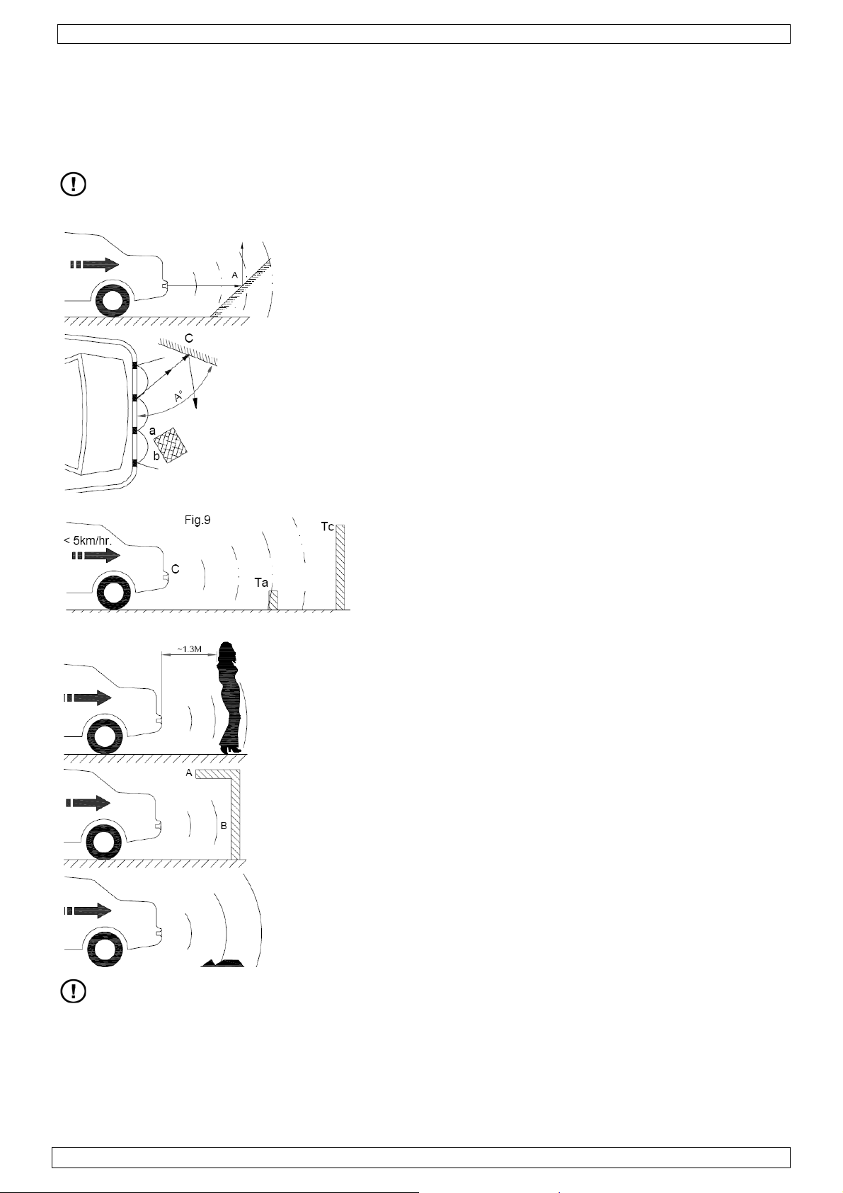
Reflection angle
Depending on the reflection angle, the reading may be
distorted.
Point A in this example may not be detected.
Reflection angle
Surface a is closer to the sensor than surface b, but
surface b has a better reflection so it will be detected first
whereas surface a may not be detected at all.
Pint C may not be detected when the surface is smooth
and shiny and angle A° is large.
Obstacle height
At first, the obstacle Ta which is below the senor is
detected. However, when Tc approaches the vehicle, its
reflection becomes stronger than that of Ta, so the
system only warns about Tc.
Surface of obstacle
Obstacles that strongly absorb ultrasonic sound waves e.g.
sponge or fabrics are difficult to detect. Due to absorption
of clothes, persons may only be detected within a range of
±1.3m behind the vehicle.
Shape
Surface B will be detected, but as surface A is located
outside the detection range, it may never be detected.
Road conditions
Rough road conditions might trigger the warning system.
The reverse speed must be below 5km/h when the parking aid system is active.
• Keep sensors clean at all times to ensure proper functioning.
• Verify on a regular basis that sensors are still properly mounted.
• Defective sensors should be replaced as soon as possible. Refer to an authorized dealer for spar
parts.
• It is strongly advised to test the system before use.
01 (09/10/2008) Velleman®
7
Page 8

SPBS8
8. Technical specifications
general
working voltage 10VDC~28VDC
max. rated current 150mA
detection distance front 0,15~0,75m
detection distance rear 0,22~2,5m
detection tolerance
working temperature -30°C~+70°C
storage temperature -35°C~+80°C
fuse internal poly fuses
LCD display
size LCD 50 x 25mm
type LCD monochrome backlit LCD
size display 70 x 39 x 23mm
volume control switch, 3 positions
rear control unit
sensor inputs 4 (1~4)
DC input +12V (from reverse light)
dimensions 120 x 77 x 25mm
front control unit
sensor inputs 4 (5~8)
DC input +12V (2x, from battery and brake light)
dimensions 120 x 77 x 25mm
sensor
number 8
Ø housing 17,6mm
dimensions Ø22mm x 19mm
Use this device with original accessories only. Velleman nv cannot be held responsible in
the event of damage or injury resulted from (incorrect) use of this device.
For more info concerning this product, please visit our website www.velleman.eu
The information in this manual is subject to change without prior notice.
±0,02m (@25°C)
.
01 (09/10/2008) Velleman®
8
Page 9

SPBS8
GEBRUIKERSHANDLEIDING
1. Inleiding
Aan alle ingezetenen van de Europese Unie
Belangrijke milieu-informatie betreffende dit product
Dit symbool op het toestel of de verpakking geeft aan dat, als het na zijn levenscyclus wordt
weggeworpen, dit toestel schade kan toebrengen aan het milieu. Gooi dit toestel (en
eventuele batterijen) niet bij het gewone huishoudelijke afval; het moet bij een
gespecialiseerd bedrijf terechtkomen voor recyclage. U moet dit toestel naar uw verdeler of
naar een lokaal recyclagepunt brengen. Respecteer de plaatselijke milieuwetgeving.
Hebt u vragen, contacteer dan de plaatselijke autoriteiten inzake verwijdering.
Dank u voor uw aankoop! Lees deze handleiding grondig voor u het toestel in gebruik neemt. Werd
het toestel beschadigd tijdens het transport, installeer het dan niet en raadpleeg uw dealer.
De SPBS8 is een intelligente parkeerhulp die gebruik maakt van piëzokeramische, ultrasone
dataprocessing. Dankzij fuzzy logic neemt dit systeem elk obstakel voor en/of achter het voertuig
waar en waarschuwt de bestuurder aan de hand van visuele en/of geluidssignalen om een aanrijding
te vermijden.
2. Veiligheidsinstructies
Houd dit toestel uit de buurt van kinderen en onbevoegden.
Enkel voor gebruik binnenshuis.
Houd de stuureenheden uit de buurt van regen, vochtigheid
• De garantie geldt niet voor schade door het negeren van bepaalde richtlijnen in deze handleiding
en uw dealer zal de verantwoordelijkheid afwijzen voor defecten of problemen die hier
rechtstreeks verband mee houden.
• Schade door wijzigingen die de gebruiker heeft aangebracht aan het toestel vallen niet onder de
garantie.
en opspattende vloeistoffen.
Elektrocutiegevaar bij installatie.
3. Algemene richtlijnen
• Bescherm het systeem tegen schokken. Vermijd brute kracht tijdens de bediening van dit toestel.
• Bescherm het systeem tegen extreme temperaturen, stof en vochtigheid.
• Leer eerst de functies van het systeem kennen voor u het gaat gebruiken.
• Om veiligheidsredenen mag de gebruiker geen wijzigingen aanbrengen aan het toestel.
• Gebruik het toestel enkel waarvoor het gemaakt is. Andere toepassingen kunnen leiden tot
kortsluitingen, brandwonden, elektrische schokken, enz. Bij onoordeelkundig gebruik vervalt de
garantie.
4. Eigenschappen
• parkeerhulp met hinderniswaarneming vooraan en achteraan
• visueel en hoorbaar alarm
• 4 ultrasone sensoren voor montage vooraan, 4 ultrasone sensoren voor montage achteraan
• 2 ECU-stuureenheden voor afzonderlijke waarneming vooraan en achteraan
• waarschuwingssignaal bij defect van een sensor
• aanduiding van de ligging van de hindernis
• 3 waarnemingszones: veilig, waarschuwing en gevaar
01 (09/10/2008) Velleman®
9
Page 10
SPBS8
Inhoud van de verpakking
• 1 lcd-display met statief en aansluitkabel
• 1 voorste stuureenheid
• 1 achterste stuureenheid
• 8 sensoren
• 4 aansluitkabels van 4,5 m voor voorste sensoren, genummerd van 5 tot 8
• 4 aansluitkabels van 2,5 m voor achterste sensoren, genummerd van 1 tot 4
• 1 aan-uitschakelaar met bekabeling (2,4 m)
• 1 voedingskabel voor stuureenheid vooraan
• 1 aansluitkabel voor stuureenheden
• 1 klokzaag Ø 18,5 mm voor sensoren
• 1 gebruikershandleiding
• kabelclips
• dubbelzijdige tape
5. Overzicht
A. achterste stuureenheid
A1. DC +12 V (van achteruitrijdlicht)
A2. GND
B. voorste stuureenheid
B1. accu ACC +12 V
B2. GND
B3. DC +12 V (van stoplicht)
C. lcd-display
D1~D8. sensoren
E. achteruitrijdlicht
F. aan-uitschakelaar
6. Installatie
Zet het systeem onder spanning NADAT u alle aansluitingen hebt gemaakt.
Sensoren
• Kies zorgvuldig waar u de sensoren wenst te installeren. De installatiehoogte is zeer belangrijk
de goede werking van het systeem.
Opmerking
beïnvloeden.
• Raadpleeg de figuur hieronder voor de horizontale en verticale positie. L = breedte van het
voertuig.
01 (09/10/2008) Velleman®
: Installatie van de sensoren in metalen bumpers kan de goede werking van het systeem
10
Page 11

SPBS8
• Zorg ervoor dat geen enkel onderdeel van de bumper de waarnemingshoek van de sensor
belemmert.
• Markeer de plaats van elk gat op de bumper en boor het gat met behulp van de meegeleverde
klokzaag (Ø 18,5 mm).
• Schuur de rand van het gat mooi vlak.
• Plaats de bekabeling en de sensor in het gat. Zorg ervoor dat de centrale as van de sensor
loodrecht op de bumper staat en dat de markering ‘UP’ naar boven is gericht (zie hieronder).
Opmerking: De sensoren kunnen in de kleur van de bumper worden overspoten indien gewenst.
Houd de laklaag echter dunner dan 0,1 mm!
De ECU-stuureenheden (Electronic Control Units)
• Raadpleeg het hoofdstuk ‘5. Omschrijving’ voor een algemeen overzicht van het systeem.
Monteer de achterste stuureenheid in de koffer, zo dicht mogelijk bij het achteruitrijdlicht. De
voorste stuureenheid wordt best gemonteerd naast de zekeringkast. Vraag raad aan een
technicus bij twijfel.
• Installeer de eenheden zo ver mogelijk van storingsbronnen zoals kabelbomen, de uitlaatpijp…
• Zorg dat de bekabeling van de eenheden na aansluiting gemakkelijk toegankelijk blijft.
• Beschadig geen kabels of vitale onderdelen tijdens het vastschroeven van de stuureenheden.
De lcd-display
• Installeer de display en het meegeleverde statief zo op het dashboard dat de display onder alle
omstandigheden gemakkelijk leesbaar is.
De bekabeling/aansluiting
• Raadpleeg het hoofdstuk ‘5. Omschrijving’ voor een algemeen overzicht van de sensoren. Houd
zeker rekening met de nummering van elke sensor! Sluit elke sensor aan de kabel met het
respectievelijke nummer, bv. sluit sensor 5 (vooraan links) via kabel 5 aan poort 5 van de
voorste stuureenheid.
• Plug de kabel in de sensor en maak vast door de kap over de aansluiting te schoreven.
• Plug het andere eind van de kabel in de overeenkomstige poort van de stuureenheid.
Aansluiting van de voeding voor de achterste stuureenheid
• De achterste stuureenheid wordt gevoed door het achteruitrijdlicht van het voertuig. Sluit aan
met behulp van de rood-zwarte voedingskabel met 2-pins connector en kabelclips.
• Haal de voedingskabel van het achteruitrijdlicht (+12 V) door een kabelclip.
01 (09/10/2008) Velleman®
11
Page 12

SPBS8
• Steek de rode kabel van de voedingskabel naar de achterste stuureenheid in dezelfde kabelclip
en druk het metalen onderdeel dicht.
• Haal de GND-kabel van het achteruitrijdlicht door de kabelclip.
• Steek de zwarte kabel van de voedingskabel naar de achterste stuureenheid in dezelfde kabelclip
en druk het metalen onderdeel dicht.
• Sluit de voedingskabel aan de achterste stuureenheid.
Aansluiting van de voeding voor de voorste stuureenheid
• De voorste stuureenheid wordt gevoed via de accu van het voertuig en geactiveerd van zodra
het stoplicht brandt. Sluit aan met behulp van de oranje-bruin-zwarte voedingskabel met 4-pins
connector en kabelclips.
• De voedingskabel voor de voorste stuureenheid bevat eveneens een aan-uitschakelaar (F) die
het hele systeem in- of uitschakelt (handig wanneer u in de file staat).
• Installeer de schakelaar (F) op een gemakkelijk bereikbare plaats in het dashboard. Gebruik
hiervoor de meegeleverde klokzaag en ga voorzichtig te werk om geen kabels of andere
onderdelen van het voertuig te beschadigen.
• Haal de voedingskabel van het stoplicht (+12 V) door een kabelclip.
• Steek de bruine kabel (B) in dezelfde kabelclip en druk het metalen onderdeel dicht.
• Haal een kabel afkomstig van de accu (bv. naar de autoradio) door de kabelclip.
• Steek de oranje kabel gemarkeerd ‘ACC’ in dezelfde kabelclip en druk het metalen onderdeel
dicht.
• Haal de GND-kabel van het stoplicht door de kabelclip.
• Steek de zwarte kabel van de voedingskabel naar de voorste stuureenheid in dezelfde kabelclip
en druk het metalen onderdeel dicht.
• Sluit de voedingskabel aan de voorste stuureenheid.
7. Gebruik
Omschrijving van de display
H. sensoren vooraan
I. sensoren achteraan
J. afstand in m (grote digits)
K. volumeregeling (achteraan)
K1. laag
K2. gemiddeld
K3. hoog
L. luidspreker (achteraan)
De parkeerhulp opstarten
• Plaats de aan-uitshakelaar (F) op ‘on’.
• Bij het schakelen in achteruit zal de parkeerhulp eenmaal piepen (0,5 seconde) om de
testprocedure aan te geven. Zowel de voorste als de achterste sensoren worden opgestart.
• Een defect wordt weergegeven door de letter ‘E’ gevolgd door het nummer van de defecte
sensor(en) en dit gedurende 3 seconden, bv. de display toont ‘E3’ indien sensor 3 defect is.
Daarna wordt de defecte sensor weergegeven doordat hij van de display verdwenen is (zie
voorbeeld hieronder).
normaal sensor 3 defect
• De parkeerhulp schakelt nu over naar de alarmstatus. Hindernissen achter de defecte
sensor(en) worden echter niet waargenomen.
• De display toont ‘EE’ indien geen van de sensoren werkt. De parkeerhulp piept dan gedurende
1,5 seconde.
• Bij het schakelen uit achteruit worden de achterste sensoren uitgeschakeld. De sensoren
vooraan worden gedurende 10 seconden ingeschakeld.
Opmerking
01 (09/10/2008) Velleman®
: De achterste sensoren zijn enkel ingeschakeld tijdens het achteruitrijden.
12
Page 13

SPBS8
De alarmstatus
• Hieronder volgt een overzicht van de verscheidene alarmniveaus.
Gevaar
Waarschuwing
Veilig
Houd rekening met de dode hoeken vooraan en achteraan uw voertuig! De dode
hoek vooraan bedraagt 15 cm, de dode hoek achteraan bedraagt 22 cm.
Hindernissen die zich in de dode hoek bevinden, worden niet waargenomen!
• De parkeerhulp piept en toont een visueel signaal op de display van zodra hij een hindernis
waarneemt binnen de alarmzone.
• Een visueel signaal bestaat uit een knipperende sensor en de afstand in meter tussen voertuig
en hindernis op de display. De afstand achteraan wordt weergegeven in grote digits, de afstand
vooraan wordt weergegeven in kleine digits.
Opmerking
: Een hindernis die in de dode hoek verdwijnt wordt op de display weergegeven door ‘-P-’.
• Via de luidspreker (L) achteraan de display (C) hoort u het audiosignaal. Regel het volume via
de 3-standenschakelaar (K) achteraan de display.
• Het interval tussen twee pieptonen geeft de afstand aan tussen voertuig en hindernis. Hoe
sneller de pieptonen, hoe dichter de hindernis. Zie tabel hieronder voor een overzicht.
Alarmzone Vooraan Achteraan
Afstand D (m) Audiosignaal Afstand D (m) Audiosignaal
Gevaar D ≤ 0,25 Bi D ≤ 0,3 Bi
0,3 < D ≤ 0,4 Bi.Bi.Bi
Opgelet 0,25 < D ≤ 0,5 Bi.Bi.Bi 0,4 < D ≤ 0,6 Bi..Bi..Bi
0,6 < D ≤ 0,8 Bi.…Bi….Bi
0,8 < D ≤ 1,0 Bi…..Bi…..Bi
Veilig 0,5 < D ≤ 0,75 Bi..Bi..Bi
1,0 < D ≤ 1,7 Bi…….Bi…….Bi
1,7 < D ≤ 2,5 -
Opmerking
: Hindernissen die zicht bevinden in de veilige zone en die worden waargenomen door
hoeksensoren 1, 4, 5 of 6, worden niet weergegeven door een audiosignaal. Pas wanneer de
hindernis zich in de gevaarzone bevindt, zal de parkeerhulp piepen.
• Zijn er meerdere hindernissen, dan zullen de overeenkomende sensoren op de display flitsen.
De parkeerhulp piept en geeft de afstand weer enkel voor de hindernis die zich in de
gevaarlijkste alarmzone bevindt.
Voorbeeld: Een hindernis bevindt zich op een afstand van 30 cm (waarschuwingszone) vooraan
het voertuig, een andere hindernis bevindt zich op een afstand van 40 cm (gevaarzone)
achteraan het voertuig. De parkeerhulp piept en geeft de afstand weer voor de hindernis
achteraan het voertuig.
01 (09/10/2008) Velleman®
13
Page 14

SPBS8
Enkele belangrijke punten
• Hoe warmer de omgevingstemperatuur, hoe korter het waarnemingsbereik. De tolerantie te
wijten aan temperatuur bedraagt 0,17 %.
• De prestaties van de parkeerhulp zijn afhankelijk van de positie van de sensoren, de vorm en de
ligging van de hindernis, reflectie, weersomstandigheden…
Vertrouw NIET ENKEL op de parkeerhulp. Houd de omgeving in het oog voor en
tijdens het parkeren.
Reflectie
De parkeerhulp geeft een verkeerde afstand weer te
wijten aan de weerkaatsing van de ultrasone frequentie.
Punt A wordt in dit voorbeeld niet waargenomen.
Hoek
Vlak a bevindt zich dichter bij het voertuig dan vlak b.
Vlak b wordt echter eerst waargenomen omdat deze de
ultrasone frequenties beter weerkaatst.
De parkeerhulp neemt hindernis C niet waar omdat de
hindernis bestaat uit een gepolijst en glanzend oppervlak,
en omdat hoek A° te groot is.
Hoogte van de hindernis
Hindernis Ta wordt als eerste waargenomen. Naarmate
het voertuig achteruitrijdt, zal de parkeerhulp enkel met
hindernis Tc rekening houden omdat hindernis Ta in de
dode hoek terechtkomt.
Oppervlak van de hindernis
Oppervlakken die ultrasone frequenties opnemen, bv.
textiel, zijn moeilijk door de parkeerhulp waarneembaar.
Personen worden bijgevolg meestal enkel waargenomen
vanaf een afstand van ± 1,3 m achteraan het voertuig.
Vorm van de hindernis
Oppervlak B wordt waargenomen maar oppervlak A niet.
Staat van de weg
Oneffen wegen kunnen de parkeerhulp inschakelen.
Houd de snelheid tijdens het achteruitrijden onder 5 km/u.
• Maak de sensoren geregeld schoon.
• Ga geregeld na of de sensoren op een correcte manier in de bumper gemonteerd zijn.
• Vervang onmiddellijk een defecte sensor. Neem contact op met een erkende dealer.
• Het is aan te raden de parkeerhulp voor de ingebruikname te testen.
01 (09/10/2008) Velleman®
14
Page 15

SPBS8
8. Technische specificaties
algemeen
voeding 10 VDC ~ 28 VDC
max. stroom 150 mA
waarnemingsbereik vooraan 0,15 ~ 0,75 m
waarnemingsbereik achteraan 0,22 ~ 2,5 m
tolerantie
werktemperatuur -30°C ~ +70°C
opslagtemperatuur -35°C ~ +80°C
zekering interne zelfherstellende zekeringen
lcd-display
afmetingen lcd-display 50 x 25 mm
type display monochroom met achtergrondverlichting
totale afmetingen 70 x 39 x 23 mm
volumeregeling 3-standenschakelaar
stuureenheid achteraan
ingangen 4 (1 ~ 4)
DC-ingang +12 V (van achteruitrijdlicht)
afmetingen 120 x 77 x 25 mm
stuureenheid vooraan
ingangen 4 (5 ~ 8)
DC-ingang +12 V (2x, van accu en stoplicht)
afmetingen 120 x 77 x 25 mm
sensoren
aantal 8
Ø behuizing 17,6 mm
afmetingen Ø 22 x 19 mm
Gebruik dit toestel enkel met originele accessoires. Velleman nv is niet aansprakelijk voor
schade of kwetsuren bij (verkeerd) gebruik van dit toestel. Voor meer informatie over dit
product, zie www.velleman.eu
. De informatie in deze handleiding kan te allen tijde
worden gewijzigd zonder voorafgaande kennisgeving.
± 0,02 m (@ 25°C)
01 (09/10/2008) Velleman®
15
Page 16

SPBS8
NOTICE D’EMPLOI
1. Introduction
Aux résidents de l'Union européenne
Des informations environnementales importantes concernant ce produit
Ce symbole sur l'appareil ou l'emballage indique que l’élimination d’un appareil en fin de
vie peut polluer l'environnement. Ne pas jeter un appareil électrique ou électronique (et
des piles éventuelles) parmi les déchets municipaux non sujets au tri sélectif ; une
déchèterie traitera l’appareil en question. Renvoyer les équipements usagés à votre
fournisseur ou à un service de recyclage local. Il convient de respecter la réglementation
locale relative à la protection de l’environnement.
En cas de questions, contacter les autorités locales pour élimination.
Nous vous remercions de votre achat ! Lire la présente notice attentivement avant la mise en
service de l’appareil. Si l’appareil a été endommagé pendant le transport, ne pas l’installer et
consulter votre revendeur.
Le SPBS8 est un système d’aide au stationnement intelligent intégrant une technologie
piézocéramique à ultrasons. Grâce à sa logique floue, il détecte les obstacles à l’avant et à l’arrière
du véhicule et avertit le conducteur à l’aide de signaux visuel et sonore.
2. Prescriptions de sécurité
Garder le système hors de la portée de personnes non
qualifiées et de jeunes enfants.
Pour usage sous abris uniquement.
Tenir les unités de contrôles l’appareil à l’écart de la pluie,
• La garantie ne s’applique pas aux dommages survenus en négligeant certaines directives de cette
notice et votre revendeur déclinera toute responsabilité pour les problèmes et les défauts qui en
résultent.
• Les dommages occasionnés par des modifications à l’appareil par le client ne tombent pas sous la
garantie.
de l’humidité et d’éclaboussures.
Risque d’électrochocs pendant l’installation.
3. Directives générales
• Protéger le système contre les chocs et le traiter avec circonspection pendant l’installation et
l’opération.
• Tenir le système à l’écart de la poussière, l’humidité et des températures extrêmes.
• Se familiariser avec le fonctionnement de l’appareil avant de l’utiliser.
• Toute modification de l’appareil est interdite pour des raisons de sécurité.
• N’utiliser le système qu’à sa fonction prévue. Tout autre usage peut causer des courts-circuits, des
brûlures, des électrochocs, etc. Un usage impropre annule d'office la garantie.
4. Caractéristiques
• aide au stationnement à détections d'obstacle antérieure et postérieure
• alarmes visuelle et sonore
• 4 capteurs à ultrasons antérieurs, 4 capteurs à ultrasons postérieurs
• 2 unités de contrôle ECU pour une détection indépendante à l'avant et à l'arrière
• dispositif d'avertissement de fonctionnement entravé d'un capteur
• dispositif d'indication de l'emplacement de l'obstacle
• 3 zones de détection : sécurité, avertissement et danger
01 (09/10/2008) Velleman®
16
Page 17

SPBS8
Contenu du kit
• 1 afficheur LCD avec support et câble
• 1 unité de contrôle antérieure
• 1 unité de contrôle postérieure
• 8 capteurs
• 4 câbles de connexion de 4,5 m pour capteurs antérieurs, numérotés de 5 à 8
• 4 câbles de connexion de 2,5 m pour capteurs postérieurs, numérotés de 1 à 4
• 1 interrupteur marche/arrêt avec câble (2,4 m)
• 1 cordon d'alimentation pour unité de contrôle antérieure
• 1 câble d'interconnexion pour les unités de contrôle
• 1 scie cloche de Ø 18,5 mm pour capteurs
• 1 notice d’emploi
• clips pour câbles
• ruban adhésif double face
5. Schéma de connexion
A. unité de contrôle postérieure
A1. CC +12 V (du feu de recul)
A2. masse GND
B. unité de contrôle antérieure
B1. batterie ACC +12 V
B2. masse GND
B3. CC +12 V (du feu de stop)
C. afficheur
D1~D8. capteurs
E. feu de recul
F. interrupteur marche/arrêt
6. Installation
NE JAMAIS mettre sous tension avant la connexion complète du système.
Les capteurs
• Choisir soigneusement l’emplacement de chaque capteur sur le pare-chocs.
Remarque
chocs métallique.
• L’illustration ci-dessous démontre les emplacements horizontal et vertical idéaux (L = largeur du
véhicule).
01 (09/10/2008) Velleman®
: Les performances des capteurs peuvent diminuer lorsqu’ils sont montés dans un pare-
17
Page 18

SPBS8
• S’assurer qu’aucune partie du pare-chocs n’est située dans la ligne de visée d’un capteur.
• Marquer l’emplacement du trou de montage et percer le trou à l’aide de la scie cloche incluse
(Ø 18,5 mm).
• Polir les bords de chaque trou.
• Insérer un capteur dans chaque trou en passant le câblage en premier. S’assurer que l’axe
central du capteur soit perpendiculaire sur la surface du pare-chocs et que le repère « UP » se
situe au haut (voir illustration ci-dessous).
Remarque : Les capteurs peuvent être repeints dans la couleur du pare-chocs si souhaité. S’assurer
que la couche ne dépasse pas une épaisseur de 0,1 mm.
Les unités de contrôle ECU
• Consulter l’illustration sous le chapitre « 5. Schéma de connexion » pour un aperçu de toutes
les pièces du système. Installer l’unité de contrôle postérieure dans le coffre près du câblage du
feu de recul. L’unité de contrôle antérieure s’installe de préférence près de la boîte à fusibles à
l’intérieur du véhicule. Consulter un technicien qualifié en cas de doute.
• Éviter d’installer les unités à proximité de source d’interférence comme p.ex. faisceau électrique
ou tuyau d’échappement…
• Installer les unités de manière à ce que les connexions restent accessibles.
• Ne pas endommager le câblage ou toute autre partie lors du montage.
L’afficheur LCD
• Fixer l’afficheur sur le tableau de bord à l’aide du support de manière à ce qu’il soit toujours
lisible.
Câblage/connexions
• Consulter l’illustration sous le chapitre « 5. Schéma de connexion » pour un aperçu de tous les
capteurs. Il est important de respecter la numérotation.
• Chaque capteur est numéroté. Connecter le câble numéroté au capteur correspondent, p.ex.
raccorder le capteur n° 5 (avant gauche) au port n° 5 de l’unité de contrôle antérieure à l’aide du
câble n° 5.
• Insérer la fiche du câble dans le capteur et fixer en vissant le capuchon sur la prise.
• Raccorder l’autre bout du câble au port correspondant de l’unité de contrôle.
01 (09/10/2008) Velleman®
18
Page 19

SPBS8
Alimentation de l’unité de contrôle postérieure
• L’unité de contrôle postérieure est alimentée depuis le circuit du feu de recul. Effectuer le
raccordement à l’aide du câble rouge/noir à connecteur 2 broches et les clips de câble inclus.
• Passer le câble d’alimentation +12 V du feu de recul dans le clips de câble.
• Insérer le conducteur rouge du câble d’alimentation dans le clips et fermer le clips.
• Passer le câble de masse GND du feu de recul dans le clips de câble.
• Insérer le conducteur noir du câble d’alimentation dans le clips et fermer le clips.
• Raccorder le câble d’alimentation à l’unité de contrôle postérieure.
Alimentation de l’unité de contrôle antérieure
• L’unité de contrôle antérieure est alimentée depuis la batterie du véhicule. Un signal provenant
du circuit du feu de stop enclenchera le système. Effectuer le raccordement à l’aide du câble
orange/marron/noir à connecteur 4 broches et les clips de câble inclus.
• Le câble d’alimentation de l’unité de contrôle antérieure est muni d’un interrupteur marche/arrêt
(F) qui permet de déclencher le système (pratique dans les embouteillages).
• Installer cet interrupteur (F) à un endroit accessible sur le tableau de bord. Percer le trou
d’installation à l’aide de la scie cloche incluse. Ne pas endommager le câblage ou toute autre
partie lors du montage.
• Passer le câble d’alimentation +12 V du circuit du feu de stop dans le clips de câble.
• Insérer le conducteur marron (B) du câble d’alimentation dans le clips et fermer le clips.
• Passer le câble de la batterie ACC (p.ex. vers l’autoradio) dans le clips de câble.
• Insérer le conducteur orange (ACC) du câble d’alimentation dans le clips et fermer le clips.
• Passer le câble de masse GND du circuit du feu de stop dans le clips de câble.
• Insérer le conducteur noir du câble d’alimentation dans le clips et fermer le clips.
• Raccorder le câble d’alimentation à l’unité de contrôle antérieure.
7. Emploi
Aperçu de l’afficheur
H. détection antérieure
I. détection postérieure
J. distance en m
K. réglage de volume (à l’arrière)
K1. bas
K2. moyen
K3. haut
L. haut-parleur (à l’arrière)
Démarrage
• Placer l’interrupteur marche/arrêt (F) en position « on ».
• En enclenchant la marche arrière le système émet une tonalité (0,5 seconde) afin d’indiquer le
processus de démarrage. Tous les capteurs sont enclenchés.
• Un capteur défectueux est indiqué avec la lettre « E » suivie du numéro du capteur (le message
« E3 » indique que le capteur n° 3 est défectueux). Après 3 secondes, l’écran ne montrera plus
l’indication du capteur défectueux en affichage normal (voir exemple ci-dessous).
Affichage normal capteur n° 3 défectueux
• Après la procédure de démarrage le système commute en mode d’alarme. Les obstacles
éventuels ne seront pas nécessairement indiqués.
• Le message « EE » s’affiche lorsqu’aucun capteur ne fonctionne. Le système émet une tonalité
pendant 1,5 seconde.
• En déclenchant la marche arrière, les capteurs postérieurs sont désactivés. Les capteurs
antérieurs resteront activés pendant 10 secondes.
Remarque
01 (09/10/2008) Velleman®
: Les capteurs postérieurs ne sont activés qu’en marche arrière.
19
Page 20

SPBS8
Mode d’alarme
• L’illustration ci-dessous est un aperçu des zones d’alarme.
danger
avertissement
sécurité
Il faut impérativement tenir compte des angles morts à l’avant (15 cm) et à
l’arrière (22 cm) du véhicule ! Les obstacles se situant dans cette zone morte ne
seront pas détectés !
• Le système émet une tonalité et affiche un signal visuel dès qu’un obstacle entre la zone
d’alarme.
• Un signal visuel consiste en un capteur clignotant et l’affichage de la distance (en m) qui sépare
le véhicule de l’obstacle (grands digits pour la distance à l’arrière ; petits digits pour la distance
à l’avant).
Remarque
: Le système affiche « -P- » lorsque l’obstacle se situe dans la zone morte.
• Le haut-parleur (L) se trouve à l’arrière de l’afficheur (C). Régler le volume à l’aide de
l’interrupteur 3 positions (K), également situé à l’arrière.
• L’intervalle entre chaque tonalité est une indication de la distance entre le véhicule et l’obstacle.
Voir la table ci-dessous.
Zone d’alarme Avant Arrière
Distance D (m) Signal audio Distance D (m) Signal audio
Danger D ≤ 0,25 Bi D ≤ 0,3 Bi
0,3 < D ≤ 0,4 Bi.Bi.Bi
Avertissement 0,25 < D ≤ 0,5 Bi.Bi.Bi 0,4 < D ≤ 0,6 Bi..Bi..Bi
0,6 < D ≤ 0,8 Bi.…Bi….Bi
0,8 < D ≤ 1,0 Bi…..Bi…..Bi
Sécurité 0,5 < D ≤ 0,75 Bi..Bi..Bi
1,0 < D ≤ 1,7 Bi…….Bi…….Bi
1,7 < D ≤ 2,5 -
Remarque
: Les obstacles se trouvant dans la zone de sécurité et détectés uniquement par les
capteurs 1, 4, 5 et 6 ne produiront pas de signal sonore. Le système n’émettra qu’un signal
une fois que l’obstacle se trouve dans la zone de danger.
• En présence de plusieurs obstacles, les capteurs correspondants clignoteront à l’écran mais
uniquement la distance de l’obstacle se trouvant dans la zone la plus dangereuse sera affichée.
Exemple : Un obstacle se trouve à une distance de 30 cm (zone d’avertissement) à l’avant du
véhicule. Un autre obstacle se trouve à une distance de 40 cm (zone de danger) à l’arrière du
véhicule). Le système émet une tonalité et n’affiche que la distance de l’obstacle situé à
l’arrière.
01 (09/10/2008) Velleman®
20
Page 21

SPBS8
Quelques points à considérer
• La portée de détection diminue à mesure que la température ambiante augmente. La tolérance
est de 0,17 %.
• Les performances de ce système dépendent de la position des capteurs, la forme et
l’emplacement de l’obstacle, les conditions climatiques…
NE JAMAIS se fier uniquement au système lors du stationnement du véhicule.
Observer la situation autour du véhicule avant et pendant la manœuvre.
Réflexion d’un obstacle
Les obstacles réfléchissant les ondes à ultrasons peuvent
influencer les données affichées.
Point A n’est pas détecté.
Angle de l’obstacle
La surface a se trouve plus proche du capteur que la
surface b. Cependant, la surface b réfléchit les ondes de
manière plus efficace que le la surface a qui ne sera pas
détectée.
Point C (surface polie et luisante, angle A° trop important)
ne sera pas détecté.
Hauteur de l’obstacle
L’obstacle Ta sera détecté en premier. À mesure que le
véhicule recule, le système négligera l’obstacle Ta et ne
tiendra compte que de l’obstacle Tc.
Nature de la surface de l’obstacle
Les obstacles absorbant les ondes à ultrasons, p.ex. du
textile, seront difficilement détectable. De ce fait, les
personnes se trouvant à l’arrière du véhicule ne seront
détectées qu’à partir d’une distance de ± 1,3 m.
Forme de l’obstacle
La surface B sera détectée, la surface A se trouve hors de
la portée des capteurs et ne sera pas détectée.
Conditions de la chaussée
Une chaussée très inégale peut enclencher le système.
Tenir la vitesse de recul en-dessous des 5 km/h.
• Nettoyer régulièrement les capteurs.
• Vérifier régulièrement l’emplacement et le montage des capteurs.
• Remplacer immédiatement un capteur défectueux. Commander des pièces de rechange
éventuelles chez votre revendeur.
• Il est conseillé de tester le système avant usage.
01 (09/10/2008) Velleman®
21
Page 22

SPBS8
8. Spécifications techniques
spécifications générales
alimentation 10 VCC ~ 28 VCC
courant max. 150 mA
portée à l’avant 0,15 ~ 0,75 m
portée à l’arrière 0,22 ~ 2,5 m
tolérance
température de service -30°C ~ +70°C
température de stockage -35°C ~ +80°C
fusibles fusibles réarmables internes
afficheur LCD
dimensions écran 50 x 25 mm
type d’afficheur monochrome à rétro-éclairage
dimensions totales 70 x 39 x 23 mm
réglage de volume interrupteurs 3 positions
unité de contrôle postérieure
entrées 4 (1 ~ 4)
entrée CC +12 V (du feu de recul)
dimensions 120 x 77 x 25 mm
unité de contrôle antérieure
entrées 4 (5 ~ 8)
entrée CC +12 V (2x, de la batterie et du feu de stop)
dimensions 120 x 77 x 25 mm
capteurs
nombre 8
Ø boîtier 17,6 mm
dimensions Ø 22 x 19 mm
N’employer cet appareil qu’avec des accessoires d’origine. SA Velleman ne sera
aucunement responsable de dommages ou lésions surve nus à un usage (incorrect ) de cet
appareil. Pour plus d’information concernant cet article, visitez notre site web
www.velleman.eu
. Toutes les informations présentées dans cette notice peuvent être
modifiées sans notification préalable.
± 0,02 m (@ 25°C)
01 (09/10/2008) Velleman®
22
Page 23

SPBS8
MANUAL DEL USUARIO
1. Introducción
A los ciudadanos de la Unión Europea
Importantes informaciones sobre el medio ambiente concerniente a este producto
Este símbolo en este aparato o el embalaje indica que, si tira las muestras inservibles,
podrían dañar el medio ambiente.
No tire este aparato (ni las pilas, si las hubiera) en la basura doméstica; debe ir a una
empresa especializada en reciclaje. Devuelva este aparato a su distribuidor o a la unidad de
reciclaje local.
Respete las leyes locales en relación con el medio ambiente.
Si tiene dudas, contacte con las autoridades locales para residuos.
¡Gracias por haber comprado el SPBS8! Lea atentamente las instrucciones del manual antes de
usarlo. Si el aparato ha sufrido algún daño en el transporte no lo instale y póngase en contacto con
su distribuidor. Daños causados por descuido de las instrucciones de seguridad de este manual
invalidarán su garantía y su distribuidor no será responsable de ningún daño u otros problemas
resultantes.
EL SPBS8 es un sistema de ayuda al estacionamiento que incluye una tecnología piezocerámica con
sensores ultrasónicos. Gracias al la tecnología "fuzzy logic" detecta obstáculos delante y detrás del
coche y avisa el conductor con señales visuales y sonoras.
2. Instrucciones de seguridad
Mantenga el aparato lejos del alcance de personas no
capacitadas y niños.
Sólo para el uso en interiores.
No exponga este equipo a lluvia, humedad ni a ningún tipo
• Daños causados por descuido de las instrucciones de seguridad de este manual invalidarán su
garantía y su distribuidor no será responsable de ningún daño u otros problemas resultantes.
• Los daños causados por modificaciones no autorizadas, no están cubiertos por la garantía.
de salpicadura o goteo.
Cuidado durante la instalación: puede sufrir una peligrosa
descarga eléctrica al tocar un cable bajo tensión.
3. Normas generales
• No agite el aparato. Evite usar excesiva fuerza durante el manejo y la instalación.
• No exponga este aparato a polvo, humedad y temperaturas extremas.
• Familiarícese con el funcionamiento del aparato antes de utilizarlo.
• Por razones de seguridad, las modificaciones no autorizadas del aparato están prohibidas.
• Utilice sólo el aparato para las aplicaciones descritas en este manual. Un uso desautorizado anula
la garantía completamente.
4. Características
• sistema de ayuda al estacionamiento con detección de obstáculos delante y detrás del coche
• alarma visual y sonora
• 4 sensores ultrasónicos frontales, 4 sensores ultrasónicos traseros
• 2 unidades de control ECU para una detección independiente en la parte delantera y la parte
trasera
• señal de advertencia en caso de un mal funcionamiento de uno de los sensores
• indicación de la posición del obstáculo
01 (09/10/2008) Velleman®
23
Page 24

SPBS8
• 3 zonas de detección: seguro, advertencia y peligro
La caja incluye
• 1 pantalla LCD con soporte y cable
• 1 unidad de control anterior
• 1 unidad de control posterior
• 8 sensores
• 4 cables de conexión de 4.5m para los sensores anteriores, numerados de 5 a 8
• 4 cables de conexión de 2.5m para los sensores posteriores, numerados de 5 a 8
• 1 interruptor ON/OFF con cable (2.4m)
• 1 cable de alimentación para la unidad de control anterior
• 1 cable de conexión para las unidades de control
• 1 trépano Ø 18.5mm para los sensores
• 1 manual del usuario
• Clips para cables
• Cinta adhesiva de doble cara
5. Esquema de conexión
A. unidad de control trasera
A1. DC +12V (de la luz de marcha
atrás)
A2. GND
B. unidad de control delantera
B1. ACC +12V
B2. GND
B3. DC +12V (de la luz de parada)
C. pantalla LCD
D1~D8. Sensor
E. luz de marcha atrás
F. Interruptor On/Off
6. Instalación
NUNCA ponga el aparato bajo tensión antes de la conexión completa del sistema.
Los sensores
• Elija cuidadosamente el lugar de montaje de cada sensor en el parachoques.
: Parachoques metálicos pueden disminuir el buen funcionamiento de los sensores.
Nota
• Véase la figura a continuación para la posición horizontal y vertical (L = anchura del vehículo).
01 (09/10/2008) Velleman®
24
Page 25

SPBS8
• Asegúrese de que ningún parte del parachoques quite la vista de de un sensor.
• Marque el lugar de instalación de cada agujero y taladre los agujeros con el trépano incluido
(Ø 18,5mm).
• Pula los bordes de de cada agujero.
• Introduzca el cable y luego el sensor en el agujero. Asegúrese de que el eje central del sensor
esté perpendicular a la superficie del parachoques y que las palabras « UP » estén orientadas
hacia arriba (véase figura abajo).
Nota: Es posible volver a pintar los sensores en el color del parachoques. Asegúrese de que la capa
no sobrepase un espesor de 0,1mm.
Las unidades de control ECU
• Véase la figura bajo el capítulo « 5. Esquema de conexión » para un resumen de todos las
piezas del sistema. Instale la unidad de control trasera en la maletera cerca de los cables de la
luz de marcha atrás. La unidad de control delantera se instale preferentemente cerca de la caja
de fusibles en el interior del vehículo. Consulte un técnico cualificado en caso de dudas.
• No instale las unidades cerca de fuentes que pueden causar interferencias como p.ej. cables o
tubo de escape, etc.
• Instale las unidades de manera que las conexiones queden accesibles.
• No dañe el cableado ni cualquier otra parte durante el montaje.
La pantalla LCD
• Fije la pantalla con el soporte en el salpicadero de manera que sea legible.
Cableado/conexiones
• Véase la figura bajo el capítulo « 5. Esquema de conexión » para un resumen de los sensores.
¡Tenga en cuenta la numeración!
• Cada sensor está numerado. Conecte el cable numerado al sensor correspondiente, p.ej. conecte
el sensor n° 5 (parte delantera izquierda) con el cable n° 5al puerto n° 5 de la unidad de control
delantera.
• Introduzca el conector del cable en el sensor y fije al atornillar el capuchón.
• Conecte el otro extremo del cable al puerto correspondiente la unidad de control.
01 (09/10/2008) Velleman®
25
Page 26

SPBS8
Alimentación de la unidad de control trasera
• La unidad de control trasera se alimenta por el circuito de la luz de marcha atrás. Efectúa la
conexión con el cable rojo/negro con conector de 2 polos y los clips de cable incluidos.
• Introduzca el cable de alimentación +12 V de la luz de marcha atrás en el clips de cable.
• Introduzca el conductor rojo del cable de alimentación en el clips y cierre el clips.
• Introduzca el cable de masa GND de la luz de marcha atrás en el clips de cable.
• Introduzca el conductor negro del cable de alimentación en el clips y cierre el clips.
• Conecte el cable de alimentación a la unidad de control trasera.
Alimentación de la unidad de control delantera
• La unidad de control delantera se alimenta por la batería del vehículo. Una señal que viene de la
luz de parada activará el sistema. Efectúa la conexión con el cable naranja/marón/negro con
conector de 4 polos y los clips de cable incluidos.
• El cable de alimentación de la unidad de control delantera está equipado con un interruptor
ON/OFF (F) que permite activar el sistema (práctico en atascos).
• Instale este interruptor (F) en un lugar accesible del salpicadero. Taladre un agujero con el
trépano incluido. No dañe el cableado ni cualquier otra parte durante el montaje.
• Introduzca el cable de alimentación +12 V de la luz de parada en el clips de cable.
• Introduzca el conductor marón (B) del cable de alimentación en el clips y cierre el clips.
• Introduzca el cable de la batería ACC (p.ej. hacia el autorradio) en el clips de cable.
• Introduzca el conductor naranja (ACC) del cable de alimentación en el clips y cierre el clips.
• Introduzca el cable de masa GND de la luz de parada en el clips de cable.
• Introduzca el conductor negro del cable de alimentación en el clips y cierre el clips.
• Conecte el cable de alimentación a la unidad de control delantera.
7. Uso
Resumen de la pantalla
H. detección delantera
I. detección trasera
J. distancia en m
K. ajuste del volumen (en la parte trasera)
K1. bajo
K2. medio
K3. alto
L. altavoz (en la parte trasera)
Activar el radar de aparcamiento
• Placer el interruptor ON/OFF (F) en la posición « on ».
• En cuanto ponga el cambio del coche en marcha atrás el sistema emite un sonido (0,5 segundo)
para indicar el procedimiento de activación. Todos los sensores se activan.
• Un sensor defectuoso se indica con la letra « E » seguido por un número del sensor (el mensaje
« E3 » indica que el sensor n° 3 está defectuoso). Después de 3 segundos, ya no indicará el
sensor defectuoso en visualización normal (véase ejemplo a continuación).
visualización
sensor n° 3 defectuoso
Después del procedimiento de activación el sistema conmuta al modo de alarma. Los obstáculos
detrás de un sensor defectuoso no se indicarán.
• El mensaje « EE » se visualiza si no funciona ningún sensor. El sistema emite un sonido durante
1,5 segundos.
• Al poner el cambio en otra marcha, los sensores traseros se desactivan. Los sensores delanteros
quedan activados durante 10 segundos.
: Los sensores traseros sólo se activan si el cambio está en marcha atrás.
Nota
01 (09/10/2008) Velleman®
26
Page 27

SPBS8
Modo de alarma
• La siguiente figura es un resumen de las zonas de alarma.
peligro
advertencia
seguridad
¡Tenga en cuenta los ángulos muertos de la parte delantera (15 cm) y trasera
(22 cm) del vehículo! ¡Los obstáculos en esta zona no se det ectarán!
• El sistema emite un sonido y visualiza una señal visual en cuanto un obstáculo entre en la zona
de alarma.
• Un señal visual consta de en un sensor intermitente y la visualización de la distancia (en m) que
separa el vehículo del obstáculo (dígitos grandes para la distancia en la parte trasera; dígitos
pequeños para la distancia en la parte delantera).
: el sistema visualiza « -P- » si el obstáculo está en la zona muerta.
Nota
• El altavoz (L) está en la parte trasera de la pantalla (C). Ajuste el volumen con el interruptor 3
posiciones (K), también de la parte trasera de la pantalla.
• El intervalo entre cada sonido indica la distancia entre el vehículo y el obstáculo. Véase la
siguiente lista.
Zona de alarma Parte delantera Parte trasera
Distancia D (m) Señal audio Distancia D (m) Señ al audi o
Peligro D ≤ 0,25 Bi D ≤ 0,3 Bi
0,3 < D ≤ 0,4 Bi.Bi.Bi
Advertencia 0,25 < D ≤ 0,5 Bi.Bi.Bi 0,4 < D ≤ 0,6 Bi..Bi..Bi
0,6 < D ≤ 0,8 Bi.…Bi….Bi
0,8 < D ≤ 1,0 Bi…..Bi…..Bi
Seguridad 0,5 < D ≤ 0,75 Bi..Bi..Bi
1,0 < D ≤ 1,7 Bi…….Bi…….Bi
1,7 < D ≤ 2,5 -
Nota
: Los obstáculos que están en la zona de seguridad y están detectados por los sensores 1, 4, 5
y 6 no emitirán una señal sonora. El sistema sólo emitirá una señal sonora en cuanto el
obstáculo esté en la zona de peligro.
• Si hay varios obstáculos, los sensores correspondientes parpadearán en la pantalla pero sólo la
distancia del obstáculo que se encuentra en la zona más peligrosa se visualizará.
Ejemplo: Un obstáculo se encuentra a una distancia de 30 cm (zona de advertencia) en parte
delantera del vehículo. Otro obstáculo se encuentra a una distancia de 40 cm (zona de peligro)
de la parte trasera del vehículo). El sistema emite un sonido y sólo visualiza la distancia del
obstáculo de la parte trasera.
01 (09/10/2008) Velleman®
27
Page 28

SPBS8
Algunos puntos importantes
• El alcance de detección disminuye a medida que la temperatura ambiente aumenta. La tolerancia
es de 0,17 %.
• El buen funcionamiento de este sistema depende de la posición de los sensores, la forma y la
posición del obstáculo, las condiciones climáticas…
NUNCA se fíe sólo del sistema al aparcar el vehículo. Observe la situación alrededor
del vehículo antes y durante la maniobra.
Reflexión de un obstáculo
Los obstáculos que reflectan las ondas ultrasónicas pueden
influir los datos visualizados.
Punto A no se detecta.
Ángulo del obstáculo
La superficie a está más cerca del sensor que la superficie
b. Sin embargo, la superficie b reflecta las ondas de
manera más eficaz que la superficie a que no se
detectará.
Punto C (superficie pulida y brillante, ángulo A°
demasiado importante) no se detectará.
Altura del obstáculo
El obstáculo Ta se detectará en primer lugar. A medida
que el vehículo da marcha atrás, el sistema ignorará el
obstáculo Ta y sólo tendrá en cuenta el obstáculo Tc.
Naturaleza de la superficie del obstáculo
Los obstáculos que absorban las ondas ultrasónicas, p.ej.
textiles, son difíciles para detectar. Por ello, las personas
que se encuentran detrás del vehículo sólo se detectarán a
partir de una distancia de ± 1,3m.
Forma del obstáculo
La superficie B se detectará, la superficie A está fuera del
alcance de los sensores y no se detectará.
Condiciones de la carretera
Una carretera muy irregular puede activar el sistema.
Asegúrese de que conduzca marcha atrás con una velocidad de menos de 5km/h.
• Limpie los sensores regularmente.
• Controle el lugar y el montaje de los sensores regularmente.
• Reemplace inmediatamente un sensor defectuoso. Contacte con su distribuidor si necesita piezas
de recambio.
• Pruebe el sistema antes del uso.
01 (09/10/2008) Velleman®
28
Page 29

SPBS8
8. Especificaciones
Especificaciones generales
alimentación 10 VCC ~ 28 VCC
corriente máx. 150mA
alcance parte delantera 0,15 ~ 0,75m
alcance parte trasera 0,22 ~ 2,5m
tolerancia
temperatura de funcionamiento -30°C ~ +70°C
temperatura de almacenamiento -35°C ~ +80°C
fusibles fusibles rearmables internos
pantalla LCD
dimensiones pantalla 50 x 25mm
tipo de pantalla monocroma con retroiluminación
dimensiones totales 70 x 39 x 23mm
ajuste del volumen interruptores 3 posiciones
unidad de control trasera
entradas 4 (1 ~ 4)
entrada CC +12 V (de la luz de marcha atrás)
dimensiones 120 x 77 x 25mm
unidad de control delantera
entradas 4 (5 ~ 8)
entrada CC +12 V (2x, de la batería y la luz de parada)
dimensiones 120 x 77 x 25mm
sensores
nombre 8
Ø caja 17,6mm
dimensiones Ø 22 x 19mm
Utilice este aparato sólo con los accesorios originales. Velleman Spain SL no será
responsable de daños ni lesiones causados por un uso (indebido) de este aparato.
Para más información sobre este producto, visite nuestra página www.velleman.eu.
Se pueden modificar las especificaciones y el contenido de este manual sin previo aviso.
± 0,02m (@ 25°C)
01 (09/10/2008) Velleman®
29
Page 30

SPBS8
BEDIENUNGSANLEITUNG
1. Einführung
An alle Einwohner der Europäischen Union
Wichtige Umweltinformationen über dieses Produkt
Dieses Symbol auf dem Produkt oder der Verpackung zeigt an, dass die Entsorgung
dieses Produktes nach seinem Lebenszyklus der Umwelt Schaden zufügen kann.
Entsorgen Sie die Einheit (oder verwendeten Batterien) nicht als unsortiertes Hausmüll;
die Einheit oder verwendeten Batterien müssen von einer spezialisierten Firma zwecks
Recycling entsorgt werden. Diese Einheit muss an den Händler oder ein örtliches
Recycling-Unternehmen retourniert werden. Respektieren Sie die örtlichen
Umweltvorschriften.
Falls Zweifel bestehen, wenden Sie sich für Entsorgungsrichtlinien an Ihre örtliche
Behörde.
Wir bedanken uns für den Kauf der SPB S8! Lesen Sie diese Bedienungsanleitung vor
Inbetriebnahme sorgfältig durch. Überprüfen Sie, ob Transportschäden vorliegen. Sollte dies der Fall
sein, verwenden Sie das Gerät nicht und wenden Sie sich an Ihren Händler.
Die SPBS8 ist eine intelligente Rückfahrhilfe mit piëzokeramischer Ultraschallsensoren. Dank Fuzzy
Logic erfasst das System jedes Hindernis vor und/oder hinter dem Fahrzeug und warnt den Fahrer
mit visuellen und/oder Tonsignalen, um einen Zusammenstoß zu vermeiden.
2. Sicherheitshinweise
Halten Sie Kinder und Unbefugte vom Gerät fern.
Nur für die Anwendung im Innenbereich.
Schützen Sie das Gerät vor Regen und Feuchte. Setzen Sie
das Gerät keiner Flüssigkeit wie z.B. Tropf- oder
• Bei Schäden, die durch Nichtbeachtung der Bedienungsanleitung verursacht werden, erlischt der
Garantieanspruch. Für daraus resultierende Folgeschäden übernimmt der Hersteller keine Haftung.
• Bei Schäden verursacht durch eigenmächtige Änderungen erlischt der Garantieanspruch.
Spritzwasser, aus.
Achtung: Stromschlaggefahr während der
Installation.
3. Allgemeine Richtlinien
• Vermeiden Sie Erschütterungen. Vermeiden Sie rohe Gewalt während der Installation und Bedienung des
Gerätes.
• Schützen Sie das Gerät vor extreme Temperaturen, Staub und Feuchte.
• Nehmen Sie das Gerät erst in Betrieb, nachdem Sie sich mit seinen Funktionen vertraut gemacht
haben.
• Eigenmächtige Veränderungen sind aus Sicherheitsgründen verboten.
• Verwenden Sie das Gerät nur für Anwendungen beschrieben in dieser Bedienungsanleitung sonst
kann dies zu Schäden am Produkt führen und erlischt der Garantieanspruch.
4. Eigenschaften
• Rückfahrhilfe mit Detektion von Hindernissen vorne und hinten
• sichtbarer und hörbarer Alarm
• 4 Ultraschallsensoren vorne, 4 Ultraschallsensoren hinten
• 2 ECU-Steuereinheiten für eine getrennte Detektion vorne und hinten
• Warnsignal bei Defekt eines Sensors
• Anzeige der Position des Hindernisses
• 3 Erfassungsbereiche: sicher, Warnung und Gefahr
01 (09/10/2008) Velleman®
30
Page 31

SPBS8
Lieferumfang
• 1 LCD-Display mit Halter und Kabel
• 1 vordere Steuereinheit
• 1 hintere Steuereinheit
• 8 Sensoren
• 4 Anschlusskabel von 4.5m für die vorderen Sensoren, nummeriert von 5 bis 8
• 4 Anschlusskabel von 2.5m für die hinteren Sensoren, nummeriert von 5 bis 8
• 1 EIN/AUS-Schalter mit Verkabelung (2.4m)
• 1 Netzkabel für die vordere Steuereinheit
• 1 Anschlusskabel für die Steuereinheiten
• 1 Lochsäge Ø 18.5mm für die Sensoren
• Kabelklemmen
• Doppelseitiges Klebeband
5. Umschreibung
A. hintere Steuereinheit
A1. DC +12 V (vom
Rückfahrscheinwerfer)
A2. GND
B. vordere Steuereinheit
B1. Batterie ACC +12 V
B2. GND
B3. DC +12 V (vom Bremslicht)
C. LCD-Display
D1~D8. Sensoren
E. Rückfahrscheinwerfer
F. EIN/AUS-Schalter
6. Installation
Setzen Sie das System unter Strom NACHDEM Sie alle Anschlüsse gemacht haben.
Sensoren
• Wählen Sie sorgfältig wo Sie die Sensoren installieren möchten. Die Montagehöhe ist sehr
wichtig für das gute Funktionieren des Systems.
Bemerkung
Funktionieren des Systems beeinflussen.
• Siehe nachfolgende Abbildung für die horizontale und vertikale Position. L = Breite des
Fahrzeuges.
01 (09/10/2008) Velleman®
: Wenn Sie die Sensoren an Stoßstangen aus Metall befestigen, könnte dies das gute
31
Page 32

SPBS8
• Beachten Sie, dass kein einziges Teil der Stoßstange den Erfassungswinkel des Sensors blockiert.
• Markieren Sie die Position von jedem Loch auf der Stoßstange und bohren Sie ein Loch mit der
mitgelieferten Lochsäge (Ø 18,5 mm).
• Schmirgeln Sie den Rand des Loches.
• Legen Sie die Verkabelung und den Sensor in das Loch ein. Beachten Sie, dass die Zentralachse
des Sensors senkrecht auf der Stoßstange steht und, dass die Markierung ‘UP’ nach oben
gerichtet ist (siehe unten).
Bemerkung
: Die Sensoren können, wenn nötig, in die Farben der Stoßstange umgespritzt werden.
Beachten Sie aber, dass die Lackschicht dünner als 0,1 mm ist!
Die ECU-Steuereinheiten (Electronic Control Units)
• Beachten Sie ‘5. Umschreibung’ für einen allgemeinen Überblick des Systems. Montieren Sie
die hintere Steuereinheit im Kofferraum, möglichst dicht am Rückfahrscheinwerfer. Die vordere
Steuereinheit installieren Sie am besten neben dem Sicherungskasten. Fragen Sie im Zweifelsfall
einen Techniker um Rat.
• Installieren Sie die Einheiten möglichst weit von Störquellen wie z.B. Kabelbündel, Auspuffrohr,
usw.
• Beachten Sie, dass die Verkabelung der Einheiten nach Anschluss einfach zugänglich bleibt.
• Beschädigen Sie keine Kabel oder vitale Teile während Sie die Steuereinheiten festschrauben.
Das LCD-Display
• Befestigen Sie das Display und den mitgelieferten Montagebügel so am Armaturenbrett, dass das
Display immer einfach lesbar ist.
Die Verkabelung/der Anschluss
• Beachten Sie ‘5. Umschreibung’ für einen allgemeinen Überblick der Sensoren. Berücksichtigen
Sie die Nummerierung jedes Sensors! Verbinden Sie jeden Sensor mit dem Kabel mit der
entsprechenden Nummer, z.B. verbinden Sie Sensor 5 (vorne links) über Kabel 5 mit Port 5 der
vorderen Steuereinheit.
• Stecken Sie das Kabel in den Sensor und machen Sie fest, indem Sie die Abdeckkappe über dem
Anschluss schrauben.
• Stecken Sie das andere Ende des Kabels in den entsprechenden Port der Steuereinheit stecken.
01 (09/10/2008) Velleman®
32
Page 33

SPBS8
Die Stromversorgung für die hintere Steuereinheit anschließen
• Die hintere Steuereinheit wird über den Rückfahrscheinwerfer des Fahrzeuges mit Strom
versorgt. Verwenden Sie das rot-schwarze Netzkabel mit 2-pol. Anschluss und Kabelklemmen.
• Stecken Sie das Netzkabel des Rückfahrscheinwerfers (+12 V) durch eine Kabelklemme.
• Stecken Sie das rote Kabel des Netzkabels der hinteren Steuereinheit in dieselbe Kabelklemme
und drücken Sie das Metallteil zu.
• Stecken Sie das GND-Kabel des Rückfahrscheinwerfers durch die Kabelklemme.
• Stecken Sie das schwarze Kabel vom Netzkabel der hinteren Steuereinheit in dieselbe
Kabelklemme und drücken Sie das Metallteil zu.
• Verbinden Sie das Netzkabel mit der hinteren Steuereinheit.
Die Stromversorgung für die vordere Steuereinheit anschließen
• Die vordere Steuereinheit wird über die Batterie des Fahrzeuges Strom versorgt und aktiviert
wenn das Bremslicht brennt. Verwenden Sie das orange-braun-schwarze Netzkabel mit 4-pol.
Anschluss und Kabelklemmen.
• Das Netzkabel für die vordere Steuereinheit verfügt ebenfalls über einen EIN/AUS-Schalter (F),
der das ganze System ein- oder ausschaltet (praktisch wenn Sie im Stau stehen).
• Befestigen Sie den Schalter (F) am Armaturenbrett, wo Sie ihn einfach erreichen können.
Verwenden Sie die mitgelieferte Lochsäge und seien Sie vorsichtig, damit Sie keine Kabel oder
anderen Teile des Fahrzeuges beschädigen.
• Stecken Sie das Netzkabel vom Bremslicht (+12 V) durch eine Kabelklemme.
• Stecken Sie das braune Kabel (B) in dieselbe Kabelklemme und drücken Sie das Metallteil zu.
• Stecken Sie das Kabel der Batterie (z.B. zum Autoradio) durch die Kabelklemme.
• Stecken Sie das orangefarbige Kabel markiert mit ‘ACC’ in dieselbe Kabelklemme und drücken
Sie das Metallteil zu.
• Stecken Sie das GND-Kabel vom Bremslicht durch die Kabelklemme.
• Stecken Sie das schwarze Kabel vom Netzkabel der vorderen Steuereinheit in dieselbe
Kabelklemme und drücken Sie das Metallteil zu.
• Verbinden Sie das Netzkabel mit der vorderen Steuereinheit.
7. Anwendung
Umschreibung des Displays
H. Sensoren vorne
I. Sensoren hinten
J. Abstand in m (große Ziffern)
K. Lautstärkeregelung (auf der Rückseite)
K1. niedrig
K2. durchschnittlich
K3. hoch
L. Lautsprecher (auf der Rückseite)
Die Rückfahrhilfe starten
• Stellen Sie den EIN/AUS-Schalter (F) auf ‘on’.
• Beim Einlegen des Rückwärtsganges wird das Gerät ein Mal piepsen (0,5 Sekunde) um das
Testverfahren anzuzeigen. Alle Sensoren (vorne und hinten) werden aktiviert.
• Ein Defekt wird mit der Buchstabe ‘E’ angezeigt. Danach erscheint die Nummer vom (von den)
defekten Sensor(en) während 3 Sekunden, z.B. das Display zeigt ‘E3’ an wenn Sensor 3 defekt
ist. Danach wird der defekte Sensor angezeigt indem er nicht mehr im Display angezeigt wird
(siehe Beispiel unten).
normal Sensor 3 defekt
• Das Gerät schaltet nun auf den Alarmmodus um. Hindernisse, die sich hinter dem (den)
defekten Sensor(en) befinden, werden aber nicht erfasst.
• Das Display zeigt ‘EE’ an wenn keiner der Sensoren funktioniert. Das Gerät piepst dann
ununterbrochen während 1,5 Sekunde.
01 (09/10/2008) Velleman®
33
Page 34

SPBS8
• Beim Einlegen des Rückwärtsganges werden die hinteren Sensoren ausgeschaltet. Die vorderen
Sensoren werden 10 Sekunden eingeschaltet.
Bemerkung: Die hinteren Sensoren sind nur beim Zurückfahren eingeschaltet.
Der Alarmmodus
• Im Folgenden gibt es einen Überblick der verschiedenen Alarmniveaus.
Gefahr
Warnung
sicher
Berücksichtigen Sie die toten Winkel vor und hinter dem Fahrzeug! Der tote Winkel
vorne beträgt 15cm, der tote Winkel hinten ist 22cm. Hindernisse, die sich im toten
Winkel befinden, werden nicht erfasst!
• Es ertönt ein Alarmsignal und es erscheint ein visuelles Signal im Display sobald das Gerät ein
Hindernis innerhalb der Alarmzone entdeckt.
• Ein visuelles Signal besteht aus einem blinkenden Sensor und dem Abstand in Meter zwischen
Fahrzeug und Hindernis im Display. Der Abstand hinten wird in großen Ziffern angezeigt, der
Abstand vorne wird in kleinen Ziffern angezeigt.
Bemerkung
: Ein Hindernis, das im toten Winkel landet, wird im Display mit ‘-P-’ angezeigt.
• Über den Lautsprecher (L) auf der Rückseite des Displays (C) ertönt das Audiosignal. Regeln Sie
die Lautstärke über den Schalter mit 3 Positionen (K) auf der Rückseite des Displays.
• Das Intervall zwischen zwei Alarmsignalen zeigt den Abstand zwischen Fahrzeug und Hindernis.
Je schneller die Alarmsignale ertönen, umso dichter befindet sich das Hindernis. Siehe
nachfolgende Liste für einen Überblick.
Alarmzone Vorne Hinten
Abstand D (m) Audiosignal Abstand D (m) Audiosignal
Gefahr D ≤ 0,25 Bi D ≤ 0,3 Bi
0,3 < D ≤ 0,4 Bi.Bi.Bi
Achtung 0,25 < D ≤ 0,5 Bi.Bi.Bi 0,4 < D ≤ 0,6 Bi..Bi..Bi
0,6 < D ≤ 0,8 Bi.…Bi….Bi
0,8 < D ≤ 1,0 Bi…..Bi…..Bi
Sicher 0,5 < D ≤ 0,75 Bi..Bi..Bi
1,0 < D ≤ 1,7 Bi…….Bi…….Bi
1,7 < D ≤ 2,5 -
Bemerkung
: Es ertönt kein Audiosignal für Hindernisse, die sich in der sicheren Zone befinden und
über die Sensoren 1, 4, 5 oder 6 entdeckt werden. Erst wenn das Hindernis sich in der
Gefahrenzone befindet, ertönt ein Alarmsignal.
• Wenn es mehrere Hindernisse gibt, so blinken die entsprechenden Sensoren im Display. Es
ertönt ein Alarmsignal und das Display zeigt nur den Abstand für das Hindernis, das sich in der
gefährlichen Alarmzone befindet, an.
Beispiel: Ein Hindernis befindet sich in einem Abstand von 30cm (Warnungszone) vor dem
Fahrzeug, ein anderes Hindernis befindet sich in einem Abstand von 40 cm (Gefahrenzone)
hinter dem Fahrzeug. Es ertönt ein Alarmsignal und das Display zeigt den Abstand für das
Hindernis hinter dem Fahrzeug an.
01 (09/10/2008) Velleman®
34
Page 35

SPBS8
Wichtige Hinweise
• Je wärmer die Umgebungstemperatur, umso kürzer ist der Erfassungsbereich. Die Toleranz,
infolge der Temperatur, ist 0,17 %.
• Die Leistungen des Gerätes hängen von der Position der Sensoren, der Form und der Position
des Hindernisses, der Reflexion, den Wetterverhältnissen, usw. Ab.
Verlassen Sie sich NIE NUR auf die Rückfahrhilfe. Berücksichtigen Sie die
Umgebung vor und während des Parkens.
Reflexion
Abhängig vom Reflexionswinkel kann das Gerät einen
falschen Abstand anzeigen.
Punkt A wird in diesem Beispiel nicht erfasst.
Winkel
Oberfläche a befindet sich dichter am Fahrzeug als
Oberfläche b. Oberfläche b wird aber als erste entdeckt
weil diese die Ultraschallfrequenzen besser reflektiert.
Das Gerät erfasst Hindernis C nicht weil das Hindernis aus
einer polierten und glänzenden Oberfläche besteht, und
weil Winkel A° zu groß ist.
Höhe des Hindernisses
Hindernis Ta wird als erstes entdeckt. In dem Maße, wie
das Fahrzeug rückwärts fährt, berücksichtigt das Gerät nur
Hindernis Tc weil Hindernis Ta im toten Winkel landet.
Oberfläche des Hindernisses
Oberflächen, die Ultraschallfrequenzen aufnehmen, z.B.
Textilien, sind vom System schwer wahrnehmbar.
Personen werden infolgedessen meistens nur ab einem
Abstand von ± 1,3m hinter dem Fahrzeug erfasst.
Form des Hindernisses
Oberfläche B wird erfasst, Oberfläche A aber nicht.
Zustand der Wege
holprige Wege können das System einschalten.
Beachten Sie das die Geschwindigkeit beim Zurückfahren weniger als 5 km/Std.
beträgt.
• Reinigen Sie die Sensoren regelmäßig.
• Überprüfen Sie regelmäßig, ob die Sensoren korrekt montiert worden sind.
• Ersetzen Sie einen defekten Sensor sofort. Bestellen Sie eventuelle Ersatzteile bei Ihrem
Fachhändler.
• Überprüfen Sie das Gerät vor Inbetriebnahme.
01 (09/10/2008) Velleman®
35
Page 36

SPBS8
8. Technische Daten
Allgemein
Stromversorgung 10 VDC ~ 28 VDC
max. Strom 150 mA
Erfassungsbereich vorne 0,15 ~ 0,75 m
Erfassungsbereich hinten 0,22 ~ 2,5 m
Toleranz
Betriebstemperatur -30°C ~ +70°C
Lagertemperatur -35°C ~ +80°C
Sicherung interne selbstrückstellende Sicherungen
LCD-Display
Abmessungen LCD-Display 50 x 25 mm
Typ Display monochrom mit Hintergrundbeleuchtung
Gesamtabmessungen 70 x 39 x 23 mm
Lautstärkeregelung Schalter mit 3 Positionen
Steuereinheit hinten
Eingänge 4 (1 ~ 4)
DC-Eingang +12 V (vom Rückfahrscheinwerfer)
Abmessungen 120 x 77 x 25 mm
Steuereinheit vorne
Eingänge 4 (5 ~ 8)
DC-Eingang +12 V (2x, vom Bremslicht und der Batterie)
Abmessungen 120 x 77 x 25 mm
Sensoren
Anzahl 8
Ø Gehäuse 17,6 mm
Abmessungen Ø 22 x 19 mm
Verwenden Sie dieses Gerät nur mit originellen Zubehörteilen. Velleman NV übernimmt
keine Haftung für Schaden oder Verletzungen bei (falscher) Anwendung dieses Gerät es.
Für mehr Informationen zu diesem Produkt, siehe www.velleman.eu
Alle Änderungen ohne vorherige Ankündigung vorbehalten.
± 0,02 m (@ 25°C)
.
01 (09/10/2008) Velleman®
36
 Loading...