

Page 1
2
E
E
T
G
M
E
A
N
P
V
À
S
D
A
P
Ó
Ä
A
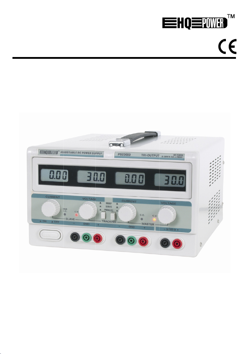
PS
DC-RE
DC-G
ALIM
FUEN
DC RE
3023
GULATED
STUURDE
NTATION
E DE ALIM
ULIERTE
OWER SU
OEDING
PILOTAG
ENTACI
NETZGER
PLY
E CC
N
CC REGUL
T
BLE
USER
GEBRU
NOTIC
MANU
BEDIE
ANUAL
IKERSHAN
D’EMPLOI
L DEL USU
UNGSANLE
LEIDING
RIO
ITUNG
4
7
1
0
1
3
1
6
Page 2
PS23023
25.01.2010 ©Velleman nv
2
Page 3

0
a
PS23
23
25.01.2010
3
©Vellem
n nv
Page 4
t
e
a
u
o
a
f
a
a
3
,
c
u
o
o
r
n
o
o
r
m
e
o
g
s
e
o
h
u
o
o
a
p
u
i
p
t
a
-
e
o
d
n
o
e
y
n
t
t
a
r
o
e
e
u
d
b
t
n
d
e
e
(
a
v
v
a
0
A
n
e
o
t
e
m
s
/
e
D
2
%
-
m
0
m
o
o
d
s
r
y
R
e
r
e
d
a
V
o
o
u
u
t
-
x
o
o
t
v
u
i
a
e
a
≤
≤
)
t
o
a
e
a
w
e
V
s
o
a
1. In
To all r
Import
If in do
Thank y
two adju
The two
high-per
30V whe
The two
voltage
ripple an
The PS2
research
2. Te
Input Vo
Two adj
- O
- O
- S
- L
- R
- P
- I
Fixed Ou
- O
- O
- S
- L
- R
- P
Environ
- O
- R
Dimensi
Operatin
3. De
Controls
(1)
(2)
(3)
25.01.201
roduction
sidents of th
nt environme
This symbol
could harm t
waste; it sho
returned to y
rules.
bt, contact y
u for choosing
stable outputs
djustable out
ormance outp
n the device is
djustable out
nd current set
d is protected
023 is a high
industrial appl
hnical Sp
ltage
stable outputs
utput Voltage
utput Current
urce Regulati
ad Regulation
ipple
otection
dication
a. Volt-in
b. Amp-i
tput
utput Voltage
utput Current
urce Regulati
ad Regulation
ipple
otection
ental Factors
perating Temp
lative humidit
ns
Time
cription
and Descriptio
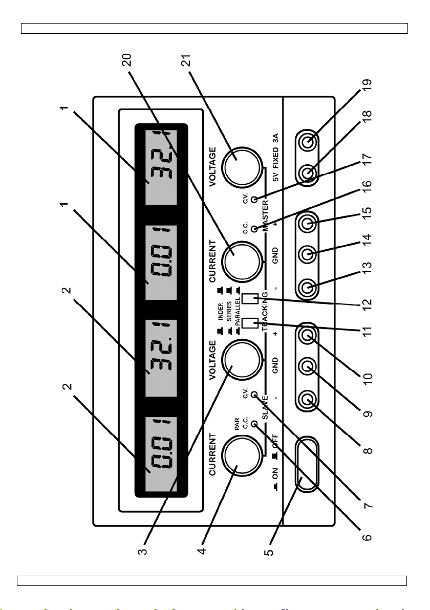
LCD: indica
LCD: indica
Slave C.V.-
0
European Un
ntal informati
n the device o
e environment
ld be taken to
ur distributor
ur local wast
Velleman®! Th
nd one fixed o
uts can be use
ts are very sta
n the "constan
uts can be con
ings. The fixed
gainst overloa
performance d
ications and us
cifications
n
ication : LCD
dication : LCD
n
rature
of the Front P
es the current
es the current
djustment: rot
PS23
USER M
ion
on about this
the package i
. Do not dispos
a specialized c
r to a local rec
disposal au
PS23023 is a
tput.
for constant v
le. The output
voltage"-mod
ected either in
output voltage
.
vice with a co
in laboratorie
: 220VAC
: 30VDC
: 3A
: C.V. ≤ 1
C.C. ≤ 2
: C.V. ≤ 1
C.V. ≤ 1
C.C. ≤ 2
C.C. ≤ 2
: C.V. ≤ 0.
C.V. ≤ 1.
C.C. < 3
: current-l
: Voltmet
LCD (LE
LED) ± 1% ±
(LED) ± 2% ±
: 5V ± 3
: 3A
: ≤ 1 x 10
: 1 x 10
: 0.5mVr
: current-l
: 0 to +4
: < 90%
: 360
: 8hrs con
nel
alue and the
alue and the
ry switch to a
4
23
NUAL
product
dicates that di
of the unit (o
mpany for rec
ycling service.
horities.
highly accurat
oltage (C.V.) o
voltage can be
.
parallel or in s
is 5V. The fixe
pact and eleg
.
50Hz ± 2Hz
-4
+ 0.5m
x 10
x 10-3 + 1mA
-4
x 10
+ 2mV (
x 10-4 + 5mV (
x 10-3 + 3mA (
x 10-3 + 5mA (
5mVrms (outp
0mVrms (outp
mArms
imiting
r & ampereme
)
digits
2 digits
4
+ 1mV
-3
s
imiting & short
°C
m x 265mm
tinuously
utput voltage
utput voltage
just the outpu
posal of the de
batteries) as
cling. This dev
espect the loc
, DC-regulated
constant curr
adjusted arbitr
ries, while the
output is very
nt design. It is
utput current
utput current
output current
output current
t current ≤ 3A)
t current > 3A
er ; 3-digit vol
circuit protecti
165mm
f the master.
f the slave.
voltage of the
ice after its lif
nsorted munici
ce should be
l environment
power supply
nt (C.C.). Thes
rily between 0
master control
stable, has a l
ideal for scient
3A)
> 3A)
3A)
> 3A)
-LCD (LED) &
n
slave.
©Vellem
cycle
pal
l
ith
two
and
the
w
ific
mp-
n nv
Page 5

PS23023
(4) Slave C.C.-adjustment: rotary switch to adjust the output current of the slave (to determine
(5) Power switch: push button used to activate/deactivate the device. Either the C.V.- or the
(6) C.C.-mode indicator of the slave output or indicator for parallel connection: this indicator is lit
(7) C.V.-mode indicator of the slave output: this indicator is lit when the slave output is in the
(8) Negative binding post of the slave output: the negative pole of the output voltage is
(9) Earthing connection of the housing: the housing is grounded.
(10) Positive binding post of the slave output: the positive pole of the output voltage is connected
(11/12) Control switches used to select independent operation, operation in parallel or in series.
(13) Negative binding post of the master output: the negative pole of the output voltage is
(14) Earthing connection of the housing: the housing is grounded.
(15) Positive binding post of the master output: the positive pole of the output voltage is
(16) Master output C.C.-indicator: this indicator is lit when the master output is in the C.C.-mode.
(17) Master output C.V.-indicator: this indicator is lit when the master output is in the C.V.-mode.
(18) Negative binding post of the fixed 5VDC-output: the negative pole of the output voltage is
(19) Positive binding post of the fixed 5VDC-output: the positive pole of the output voltage is
(20) Master output C.C.-adjustment: rotary switch used to adjust the current value of the master
(21) Master output C.V.-adjustment: rotary switch used to adjust the voltage value of the master
the current-limiting point)
C.C.-indicator is lit when the device is activated.
when the slave output is in the C.C.-mode or when the two adjustable outputs are connected
in parallel.
C.V.-mode.
connected to the negative terminal of the load being tested.
to the positive terminal of the load being tested.
connected to the negative terminal of the load being tested.
connected to the positive terminal of the load being tested.
connected to the negative terminal of the load being tested.
connected to the positive terminal of the load being tested.
output (adjustment of the current-limiting point).
output.
4. Operating Procedure
1) Independent use of the two adjustable outputs
- Place switches (11) and (12) in the OFF-position.
- Proceed as follows when the adjustable outputs are used as C.V.-outputs: put the C.C.-control
switches (4) and (20) in the max. position and use the power switch (5) to activate the device.
Install the required DC output voltage for both master and slave using the rotary switches for C.V.adjustment (3) and (21). The C.V.-indicators (7) and (17) will light.
- Proceed as follows when the adjustable outputs are used as C.C.-outputs: Use the power switch (5)
to activate the device. Put the C.V.-control switches (3) and (21) in the max. position and place the
C.C.-control switches (4) and (20) in the min. position. Connect the required load and install the
required output current by means of rotary switches (4) and (20). The C.V.- mode indicators (7) and
(17) will extinguish and the C.C.-mode indicators (6) and (16) will light.
- The C.C.-control switches (4) and (20) are generally placed in the max. position when the adjustable
outputs are used as C.V.-outputs. With this particular device, however, the current-limiting point can
be set by the user. Use the following procedure: Switch on the device and place the C.C.-control
switches (4) and (20) in the min. position. Short the positive and negative output terminals.
Consequently, the user should adjust the position of the C.C.-control switches (4) and (20) until the
output current matches the required current-limiting point.
2) Connecting the two adjustable outputs in series
- Place switch (11) in the ON-position and leave switch (12) in the OFF-position. When the user adjusts
the output voltage of the master (21), the slave output will automatically follow suit. The max.
output voltage is 60V (voltage between the terminals of (8) and (15)).
- Examine whether the negative terminals of both the master and slave output are connected to the
"GND"-terminal (ground). If so, the user should disconnect them in order to avoid a short-circuit
when the two outputs are connected in series.
- When the two outputs are connected in series, the output voltage is controlled by the master output.
The current adjustments of the two outputs, however, are still independent of each other. This is why
the user should check the position of the C.C.-control switch (4). The voltage of the slave output will
25.01.2010 ©Velleman nv
5
Page 6

PS23023
not be identical to the voltage of the master if, for example, the C.C.-control switch (4) is in the min.
position or if the current of the slave output exceeds the current-limiting point. Consequently, the
C.C.-control switch (4) should be placed in the max. position when the two adjustable outputs are
connected in series.
- Use appropriate test leads to short the negative terminal of the master output with the positive
binding post of the slave output if the two adjustable outputs are connected in series. Failure to do
this will cause the current to run through the shorted switch, as the negative terminal of the master
output is shorted by switch (11). This will affect the reliability of the device.
3) Parallel use of the two adjustable outputs
- Put both switch (11) and (12) in the ON-position. The two adjustable outputs are now connected in
parallel. Use control switch (21) to adjust the C.V. of the master output. The voltage of master and
slave will remain identical to each other and the C.C.-indicator (6) of the slave output will light.
- The C.C.-control switch (4) of the slave output does not work when the two adjustable outputs are
connected in parallel. Subsequently, the operator should use the C.C.-switch (20) of the master
output when one of the adjustable outputs is used as constant current supply. The output current of
the master and slave outputs are identical to each other and both are now controlled by (20).
- Use test leads to connect the two positive and negative terminals of the master and slave outputs
when the two adjustable outputs are connected in parallel. This is necessary to ensure a reliable
connection between the load and the two outputs connected in parallel. The current of the two
outputs may not be identical if the load is connected to only one output terminal. This may cause
damage to series/parallel switches (11) and (12).
- The digital display carries 3 digits. Use a more precise measuring instrument to calibrate the load if
you need a more accurate indication.
4) Warning
- The 5V-output has optimal protection thanks to the short-circuit protection and the current-limiting
point, a feature also present in the two adjustable outputs. The power loss in case of short circuit is
limited thanks to the protection circuit that controls the power loss of the transistors in the power
supply. This feature keeps the device from being damaged. Nevertheless, the short circuit should be
repaired as soon as possible in order to prevent wear and unnecessary power consumption.
- Store the device in a dry and well-ventilated environment and keep it clean. Remove the power plug
if the device is to be stored for a prolonged period of time.
Use this device with original accessories only. Velleman nv cannot be held responsible in the
event of damage or injury resulted from (incorrect) use of this device. For more info
concerning this product and the latest version of this user manual, please visit our website
www.velleman.eu. The information in this manual is subject to change without prior notice.
© COPYRIGHT NOTICE
This manual is copyrighted. The copyright to this manual is owned by Velleman nv.
All worldwide rights reserved. No part of this manual may be copied, reproduced, translated or reduced
to any electronic medium or otherwise without the prior written consent of the copyright holder.
25.01.2010 ©Velleman nv
6
Page 7

e
v
e
n
e
3
h
c
s
g
e
e
e
a
t
e
e
e
W
e
g
r
v
f
o
n
e
n
t
c
o
n
e
h
t
z
p
e
g
a
a
g
g
U
e
e
f
h
n
e
p
3
w
r
a
g
e
s
D
r
0
A
o
e
k
e
t
r
n
h
e
e
n
V
D
s
s
s
s
s
s
s
s
s
o
mAmp
±
±
x
1
m
o
t
0
m
D
m
o
e
e
r
t
e
n
s
t
a
e
b
x
t
n
m
e
a
s
a
5
A
m
m
A
A
u
u
t
e
a
o
n
r
e
n
e
o
o
o
o
≤
)
n
1. Inl
Aan all
Belangr
Hebt u
Proficiat
uitgange
De twee
Deze tw
worden i
De twee
stroomr
uitgang i
De PS2
wetensc
2. Te
Ingangs
Twee re
- U
- U
- R
- R
≤ 3A)
> 3A)
3A)
3A)
- R
- B
- A
Vaste ui
- U
- U
- R
- R
- R
- B
Omgevin
-
- R
Afmetin
Max. we
eiding
ingezetenen
ijke milieu-in
Dit symbool
weggeworpe
batterijen) ni
terechtkome
recyclagepun
ragen, conta
met uw aankoo
n en één vaste
regelbare uitga
e uitgangen zij
gesteld op 0 t
variabele uitga
gelingen via d
s zeer stabiel,
023 is compac
appelijk onder
hnische s
panning
elbare uitgang
itgangsspannin
itgangsstroom
geling van de
geling van de
impelspanning
scherming
nduiding
a. Volt-a
b. Amp-a
gang
itgangsspannin
itgangsstroom
geling van de
geling van de
impelspanning
scherming
gsfactoren
erktemperatuu
latieve vochti
en
ktijd
GEBR
an de Europ
ormatie betr
p het toestel o
, dit toestel sc
t bij het gewo
voor recyclag
brengen. Res
teer dan de p
p! De PS2302
uitgang.
ngen kunnen
n zeer stabiel e
t 30V wannee
gen kunnen p
mastervoedin
eeft een lage r
en elegant en
oek, industriël
ecificatie
n
bron
belasting
nduiding : LCD
nduiding : LC
bron
belasting
heid
PS23
IKERSH
se Unie
ffende dit pr
de verpakking
ade kan toebr
e huishoudelij
. U moet dit to
ecteer de plaat
laatselijke au
is een zeer p
orden gebruikt
n van uitsteke
het toestel zic
rallel of in seri
gebeuren. De
impelspanning
levert uitsteke
toepassingen
: 220
: 30V
: 3A
: con
con
: con
con
con
con
: con
con
con
: Stro
: Volt
(LED) ± 1% ±
(LED) ± 2%
: 5V
: 3A
: ≤ 1
: 1 x
: 0.5
: stro
: 0 to
: < 9
: 360
: 8u a
23
NDLEI
duct
geeft aan dat,
ngen aan het
e afval; het m
stel naar uw v
selijke milieuw
oriteiten bet
ecieze, DC-ges
voor constante
de kwaliteit. D
in de "consta
worden gesch
vaste uitgangs
n is beveiligd
de prestaties.
en gebruik in l
AC/50Hz ± 2H
C
tante spanning
tante stroom ≤
tante spanning
tante spanning
tante stroom ≤
tante stroom ≤
tante spanning
tante spanning
tante stroom <
mbegrenzing
eter & ampèr
-LCD (LED)
2 digits
2 digits
3%
10-4 + 1mV
-3
0
Vrms
mbegrenzing,
+40°C
%
m x 265mm
an een stuk bij
ING
als het na zijn l
ilieu. Gooi dit
et bij een gesp
rdeler of naar
tgeving.
effende de ve
uurde voeding
spanning of co
uitgangsspan
te spanning"-
akeld, terwijl d
panning bedra
egen overbela
Het is een idea
boratoria.
z
-4
≤ 1 x 10
2 x 10⁻³ + 1m
≤ 1 x 10⁻⁴ + 2
≤ 1 x 10⁻⁴ + 5
2 x 10⁻³ + 3m
2 x 10⁻³ + 5m
≤ 0.5mVrms (
≤ 1.0mVrms (
3mArms
meter ; 3-digi
eschermd teg
165mm
max. belasting
+ 0.
evenscyclus w
oestel (en eve
ecialiseerd bed
een lokaal
rwijdering.
met twee regel
nstante stroom
ing kan willek
ode bevindt.
spannings- e
gt 5V. De vast
ting.
l toestel voor
mV
V (uitgangsstr
V (uitgangsstr
(uitgangsstro
(uitgangsstro
itgangsstroom
itgangsstroom
Volt LCD (LED
n kortsluitinge
rdt
tuele
ijf
bare
.
urig
om
om
m ≤
m >
3A)
> 3A)
&
25.01.201
0
7
©Vellem
n nv
Page 8

PS23023
3. Omschrijving
Regelingen en beschrijving van het frontpaneel
(1) LCD: geeft de stroom en de uitgangsspanning van de master aan.
(2) LCD: geeft de stroom en de uitgangsspanning van de slave aan.
(3) Regeling voor constante spanning van de slave: draaiknop om de uitgangsspanning van de
slave te regelen.
(4) "Constante stroom"-regeling van de slave: draaiknop om de uitgangsstroom van de slave te
regelen (om de stroombegrenzing in te stellen).
(5) Voedingsschakelaar: drukknop om het toestel in of uit te schakelen. De indicator voor
constante spanning of constante stroom brandt wanneer het toestel is ingeschakeld.
(6) "Constante stroom"-indicator van de slave of indicator voor parallelschakeling: deze indicator
brandt wanneer de twee regelbare uitgangen parallel geschakeld zijn of wanneer de slaveuitgang zich in de "constante stroom"-mode bevindt.
(7) Indicator voor constante spanning van de slave: deze indicator gaat branden wanneer de
slave zich in de "constante spanning"-mode bevindt.
(8) Negatieve aansluitklem van de slave-uitgang: de negatieve pool van de uitgangsspanning is
verbonden met de negatieve aansluitklem van de belasting die wordt getest.
(9) Aardingaansluiting van de behuizing: de behuizing is geaard.
(10) Positieve aansluitklem van de slave-uitgang: de positieve pool van de uitgangsspanning is
verbonden met de positieve aansluitklem van de belasting die wordt getest.
(11/12) Keuzeschakelaars voor de twee regelbare uitgangen: selecteren van onafhankelijke
bediening, parallelschakeling of serieschakeling.
(13) Negatieve aansluitklem van de masteruitgang: de negatieve pool van de uitgangsspanning is
verbonden met de negatieve aansluitklem van de belasting die wordt getest.
(14) Aardingaansluiting van de behuizing: de behuizing is geaard.
(15) Positieve aansluitklem van de masteruitgang: de positieve pool van de uitgangsspanning is
verbonden met de positieve aansluitklem van de belasting die wordt getest.
(16) "Constante stroom"-indicator van de masteruitgang: deze indicator gaat branden wanneer de
masteruitgang zich in de "constante stroom"-mode bevindt.
(17) "Constante spanning"-indicator van de masteruitgang: deze indicator gaat branden wanneer
de masteruitgang zich in de "constante spanning"-mode bevindt.
(18) Negatieve aansluitklem van de vaste 5VDC-uitgang: de negatieve pool van de
uitgangsspanning is verbonden met de negatieve aansluitklem van de belasting die wordt
getest.
(19) Positieve aansluitklem van de vaste 5VDC-uitgang: de positieve pool van de
uitgangsspanning is verbonden met de positieve aansluitklem van de belasting die wordt
getest.
(20) "Constante stroom"-regeling van de masteruitgang: draaiknop om de stroomwaarde van de
masteruitgang te regelen (instellen van de stroombegrenzing).
(21) "Constante spanning"-regeling van de masteruitgang: draaiknop om de spanningswaarde van
de masteruitgang te regelen.
4. Bedieningsinstructies
1) Onafhankelijk gebruik van de twee regelbare uitgangen
- Plaats schakelaars (11) en (12) in de OFF-stand.
- Gebruik de volgende procedure wanneer de regelbare uitgangen worden gebruikt als uitgangen voor
constante spanning: plaats de "constante stroom"-regelaars (4) en (20) in de max. stand en gebruik
de voedingsschakelaar (5) om het toestel in te schakelen. Stel de vereiste DC uitgangsspanning in
voor master en slave d.m.v. de draaiknoppen (3) en (21) voor "constante spanning"-regeling. De
indicators voor constante spanning (7) en (17) gaan branden.
- Gebruik de volgende procedure wanneer de regelbare uitgangen worden gebruikt als uitgangen voor
constante stroom: gebruik de voedingsschakelaar (5) om het toestel in te schakelen. Plaats de
"constante spanning"-regelaars (3) en (21) in de max. stand en plaats de "constante stroom"regelaars (4) en (20) in de min. stand. Verbind de belasting met de aansluitklemmen en gebruik (4)
en (20) om de vereiste uitgangsstroom in te stellen. De indicators voor constante spanning (7) en
(17) doven uit en de indicators voor de "constante stroom"-mode (6) en (16) gaan branden.
- Doorgaans worden de regelingen voor constante stroom (4) en (20) in de max. stand geplaatst
wanneer de regelbare uitgangen worden gebruikt als uitgangen voor constante spanning. Bij dit
toestel kan de gebruiker de stroombegrenzing echter zelf instellen. Ga als volgt te werk: schakel het
toestel in en plaats de "constante stroom"-regelaars (4) en (20) in de min. positie. Sluit de positieve
25.01.2010 ©Velleman nv
8
Page 9

PS23023
en de negatieve uitgangsaansluiting kort. Stel de "constante stroom"-regelaars (4) en (20)
vervolgens zo in dat de uitgangsstroom overeenkomt met het vereiste stroombegrenzingspunt.
2) De twee regelbare uitgangen zijn in serie geschakeld
- Plaats schakelaar (11) in de ON-stand en schakelaar (12) in de OFF-stand. Wanneer u de uitgangsspanning
van de master regelt (21), zal de uitgangsspanning van de slave nu automatisch volgen. De max.
uitgangsspanning bedraagt 60V (spanning tussen de aansluitklemmen van (8) en (15)).
- Ga na of de negatieve aansluitklemmen van de uitgangen van master en slave aangesloten zijn op de
"GND"-aansluitklem (aarding). Ontkoppel ze indien dit het geval is : zo vermijdt u een kortsluiting
wanneer de twee uitgangen in serie worden geschakeld.
- De uitgangsspanning wordt geregeld door de masteruitgang wanneer de twee uitgangen in serie zijn
geschakeld, maar de stroomregelingen van de twee uitgangen gebeuren nog steeds onafhankelijk
van elkaar. Daarom moet de gebruiker de positie van de "constante stroom"-regelaar (4)
controleren. De spanning van de slave-uitgang zal de spanning van de masteruitgang niet
automatisch volgen indien, bijvoorbeeld, de "constante stroom"-regelaar (4) in de min. stand staat of
indien de stroom van de slave-uitgang hoger is dan de ingestelde stroombegrenzing. De"constante
stroom"-regelaar (4) moet bijgevolg in de max. stand worden geplaatst wanneer de twee regelbare
uitgangen in serie zijn geschakeld.
- Gebruik geschikte testsnoeren om de negatieve aansluitklem van de masteruitgang kort te sluiten
met de positieve aansluitklem van de slave-uitgang indien de twee regelbare uitgangen in serie zijn
geschakeld. Doet u dit niet, dan loopt de stroom door de kortgesloten schakelaar aangezien de
negatieve aansluitklem van de masteruitgang wordt kortgesloten door schakelaar (11). Dit zal de
betrouwbaarheid van het toestel negatief beïnvloeden.
3) De twee regelbare uitgangen zijn parallel geschakeld
- Plaats schakelaars (11) en (12) in de ON-stand. De twee regelbare uitgangen zijn nu parallel
geschakeld. Gebruik draaiknop (21) om de constante spanning van de masteruitgang te regelen. De
spanning van master en slave blijven gelijk aan elkaar en de indicator (6) van de "constante
stroom"-uitgang van de slave gaat branden.
- De "constante stroom"-regeling (4) van de slave-uitgang werkt niet indien de twee regelbare
uitgangen parallel geschakeld zijn. Gebruik dus de "constante stroom"-regelaar (20) van de
masteruitgang wanneer één van de twee regelbare uitgangen wordt gebruikt als "constante stroom"voeding. De uitgangsstroom van slave- en masteruitgang zijn nu identiek aan elkaar en worden
geregeld door (20). De max. uitgangsstroom bedraagt 6A.
- Indien de twee regelbare uitgangen parallel geschakeld zijn, moet u testsnoeren gebruiken om de
twee positieve en negatieve aansluitklemmen van de masteruitgang en de slave-uitgang met elkaar
te verbinden. Dit is noodzakelijk om een betrouwbare verbinding te creëren tussen de belasting en
de twee parallel geschakelde uitgangen. De stroom van de twee uitgangen kan verschillend zijn
indien de belasting slechts is aangesloten op één van de uitgangsaansluitingen. Dit kan ook leiden tot
beschadiging van de serie-/parallelschakelaars (11) en (12).
- Er verschijnen max. 3 digits op de display. Gebruik een meetinstrument met een grotere precisie om
de belasting te ijken indien u een preciezere uitlezing wenst.
4) Waarschuwing
- De 5V-uitgang is optimaal beveiligd dankzij de beveiliging tegen kortsluiting en de stroombegrenzing,
een eigenschap die we ook terugvinden bij de twee regelbare uitgangen. Het spanningsverlies bij
kortsluiting blijft beperkt dankzij het beveiligingscircuit dat het spanningsverlies van de transistoren
in de voeding regelt, zodat het toestel niet kan worden beschadigd. Dit beperkte spanningsverlies
neemt niet weg dat de kortsluiting zo snel mogelijk ongedaan moet worden gemaakt om slijtage en
onnodig stroomverbruik te vermijden.
- Bewaar het toestel in een droge en goed geventileerde omgeving en reinig het geregeld. Ontkoppel
de stekker indien u het toestel voor lange tijd wil opbergen.
Gebruik dit toestel enkel met originele accessoires. Velleman nv is niet aansprakelijk voor
schade of kwetsuren bij (verkeerd) gebruik van dit toestel. Voor meer informatie over dit
product en de meest recente versie van deze handleiding, zie www.velleman.eu. De informatie
in deze handleiding kan te allen tijde worden gewijzigd zonder voorafgaande kennisgeving.
© AUTEURSRECHT
Velleman nv heeft het auteursrecht voor deze handleiding. Alle wereldwijde rechten
voorbehouden. Het is niet toegestaan om deze handleiding of gedeelten ervan over te nemen, te
kopiëren, te vertalen, te bewerken en op te slaan op een elektronisch medium zonder voorafgaande
schriftelijke toestemming van de rechthebbende.
25.01.2010 ©Velleman nv
9
Page 10

t
d
r
e
v
e
t
e
t
0
u
é
t
n
u
g
g
n
t
e
n
u
g
g
n
t
n
m
m
n
e
s
o
o
é
a
P
l
e
m
i
s
e
n
n
n
e
n
q
v
u
e
(
O
i
e
s
n
g
o
e
l
l
n
o
n
e
(
c
c
e
a
0
e
e
n
p
a
r
u
±
n
n
t
t
n
n
n
m
m
n
g
o
I
o
o
é
c
e
n
o
o
e
p
l
0
m
m
m
m
m
(
(
i
n
s
a
p
p
e
d
d
e
e
r
r
e
e
D
t
e
a
t
e
e
o
l
e
f
L
s
s
1. In
Aux rési
Des info
En cas d
Merci de
réglables
Les deux
sont d'un
mode de
Les deux
tension s
est très s
La PS23
scientifiq
2. Sp
Tension d
Deux sor
- Te
- Co
- Ré
- Ré
- Te
- Pro
- Ind
Sortie fix
- Te
- Co
- Ré
- Ré
- Te
- Pro
Circonsta
- Te
- Hu
Dimensio
Durée d'
3. De
Réglages
(1)
(2)
(3)
(4)
roduction
ents de l'Unio
mations envir
Ce symbole su
polluer l'envir
parmi les déch
Renvoyer les
de respecter l
questions, co
otre achat! La
et d'une sortie fi
sorties variables
excellente qua
ension courant
sorties variables
font au moyen
able, elle a une
23 est aussi co
es, des applicat
cification
'entrée
ies variables
sion de sortie
rant de sortie
lage de la sourc
lage de la charg
sion d'ondulatio
ection
ication
a. Indicatio
b. Indicatio
sion de sortie
rant de sortie
lage de la sourc
lage de la charg
sion d'ondulatio
ection
ces atmosphéri
pérature de tra
idité relative
s
mploi max.
cription
et description d
LCD: affiche
LCD: affiche
Réglage de t
de l'esclave.
Réglage de c
de l'esclave
N
TICE D
n européenne
nnementales
r l'appareil ou l'
nnement. Ne pa
ets municipaux
quipements usa
réglementation
ntacter les aut
S23023 est un
xe.
s'utilisent pour
ité. La tension d
.
peuvent être re
de l'alimentatio
basse tension d'
pacte et éléga
ons industrielles
techniqu
:
e :
résiduelle :
de volts : LCD
d'ampères : LC
:
e :
résiduelle :
ues
ail :
panneau fronta
la tension et le
la tension et le
nsion constant
ourant constant
pour instaurer l
mportantes co
mballage indiqu
jeter un appar
on sujets au tri
és à votre four
locale relative à
rités locales
alimentation à
a tension consta
e sortie est régl
iées en parallèle
maître ("maste
ndulation résid
te que performa
et pour usage d
s
:
220VCA/50Hz
30VCC
:
3A
:
tension consta
courant consta
tension constan
tension constan
courant constan
courant constan
tension consta
tension consta
courant consta
:
limitation de co
:
voltmètre & am
LED) ± 1% ± 2
D (LED) ± 2% ±
:
5V ± 3%
:
3A
≤ 1 x 10
1 x 10
0.5mVrms
:
limitation de co
0 à +40°C
< 90%
:
360mm x 265
:
:
8h d'emploi co
-4
-3
l
ourant de sortie
ourant de sortie
de l'esclave: ré
de l'esclave: rég
limitation de c
PS23
’EMPLO
ncernant ce pr
il électrique ou
sélectif ; une dé
isseur ou à un s
la protection de
our éliminatio
pilotage CC à ha
nte ou pour le c
ble de 0 à 30V l
ou en série, tan
nte. Cet apparei
ans un laboratoi
te ≤ 1 x 10⁻⁴ +
e ≤ 1 x 10⁻⁴ + 2
e ≤ 1 x 10⁻⁴ + 5
t ≤ 2 x 10⁻³ + 3
t ≤ 2 x 10⁻³ + 5
te ≤ 0.5mVrms
te ≤ 1.0mVrms
urant
pèremètre ; 3-d
digits
2 digits
+ 1
V
urant, protectio
m x 165mm
tinu
du maître ("ma
de l'esclave ("sl
lage rotatif qui
urant).
23
que l’éliminati
"). La tension d
elle et elle est
2Hz
t ≤ 2 x 10⁻³ + 1
t < 3mArms
lage rotatif qui
duit
n d’un appareil
lectronique (et
hèterie traitera
rvice de recycla
l’environnement
.
ute précision, éq
urant constant.
rsque l'appareil
dis que les régla
sortie fixe est
rotégée contre l
est idéal pour l
re.
.5mV
A
V (courant de so
V (courant de so
A (courant de so
A (courant de so
courant de sorti
courant de sorti
git Volt LCD (LE
contre les cour
ter").
ve").
ermet d'instaur
ermet d'instaur
n fin de vie peu
es piles éventu
l’appareil en qu
ge local. Il convi
.
uipée de deux s
Ces sorties stab
se trouve dans l
ges de courant
e 5V. La sortie
s surcharges.
s recherches
tie ≤ 3A)
tie > 3A)
rtie ≤ 3A)
rtie > 3A)
≤ 3A)
> 3A)
) & Amp-LCD (
s-circuits
er la tension de
r le courant de
lles)
stion.
ent
rties
es
e
t de
ixe
ED)
ortie
ortie
25.01.201
0
10
©Vellem
n nv
Page 11

PS23023
(5) Interrupteur d'alimentation: Bouton-poussoir pour l'activation/la désactivation de l'appareil.
(6) Indicateur du courant constant de l'esclave ou indicateur de deux sorties reliées en parallèle: cet
(7) Indicateur du mode de tension constante de l'esclave : cet indicateur s'allume lorsque l'esclave se
(8) Borne de connexion négative de la sortie esclave: le pôle négatif de la tension de sortie est branché
(9) Connexion de terre du boîtier: le boîtier est mis à la terre.
(10) Borne de connexion positive de la sortie esclave: le pôle positif de la tension de sortie est branché à
(11/12) Sélecteurs pour les deux sorties variables: permettent de sélectionner l'opération séparée, la
(13) Borne de connexion négative de la sortie maître: le pôle négatif de la tension de sortie est branché à
(14) Connexion de terre du boîtier : le boîtier est mis à la terre.
(15) Borne de connexion positive de la sortie maître: le pôle positif de la tension de sortie est branché à
(16) Indicateur du courant constant de la sortie maître: cet indicateur s'allume lorsque la sortie maître se
(17) Indicateur de la tension constante de la sortie maître: cet indicateur s'allume lorsque la sortie maître
(18) Borne de connexion négative de la sortie 5VCC fixe: le pôle négatif de la tension de sortie est
(19) Borne de connexion positive de la sortie 5VCC fixe: le pôle positif de la tension de sortie est branché
(20) Réglage du courant constant de la sortie maître: réglage rotatif qui permet d'instaurer le courant
(21) Réglage de la tension constante de la sortie maître: réglage rotatif qui permet d'instaurer la tension
L'indicateur de courant constant ou celui de tension constante sera activé lorsque l'appareil est
branché.
indicateur s'allume lorsque la sortie de l'esclave se trouve dans le mode de courant constant ou
lorsque les deux sorties réglables sont reliées en parallèle.
trouve dans le mode de tension constante.
à la borne de connexion négative de la charge à tester.
la borne de connexion positive de la charge à tester.
connexion en parallèle ou la connexion en série des deux sorties variables.
la borne de connexion négative de la charge à tester.
la borne de connexion positive de la charge à tester.
trouve dans le mode de courant constant.
se trouve dans le mode de tension constante.
branché à la borne de connexion négative de la charge à tester.
à la borne de connexion positive de la charge à tester.
désiré de la sortie maître (instauration de la limitation de courant).
désirée de la sortie maître.
4. Instructions d’opération
1) Usage séparé des deux sorties variables
- Mettez les interrupteurs (11) et (12) dans la position OFF.
- Utilisez la procédure suivante lorsque les sorties variables sont utilisées en tant que sorties de tension
constante : mettez les réglages de tension constante (4) et (20) dans la position max. et activez l'appareil au
moyen de l'interrupteur d'alimentation (5). Instaurez la tension de sortie CC désirée pour les sorties maître
et esclave avec les réglages rotatifs de tension constante (3) et (21). Les indicateurs de tension constante
(7) en (17) s'allument.
- Utilisez la procédure suivante lorsque les sorties variables sont utilisées en tant que sorties de courant
constant : activez l'appareil au moyen de l'interrupteur d'alimentation (5). Mettez les réglages de tension
constante (3) et (21) dans la position max. et les réglages de courant constant (4) et (20) dans la position
min. Branchez la charge aux bornes de connexion et utilisez (4) et (20) afin d'instaurer le courant de sortie.
Les indicateurs de tension constante (7) et (17) s'éteignent et les indicateurs de courant constant (6) et (16)
s'allument.
- D'habitude les réglages de courant constant (4) et (20) sont mis dans la position max. lorsque les sorties
réglables sont utilisées en tant que sorties de tension constante. Cependant, la PS23023 permet à
l'utilisateur d'instaurer la limitation de courant soi-même. Agissez comme suit : branchez l'appareil et mettez
les réglages de courant constant (4) et (20) dans la position min. Court-circuitez la borne de sortie positive
et négative. Utilisez par la suite les réglages de courant constant (4) et (20) pour instaurer le courant de
sortie qui correspond au point de limitation de courant requis.
2) Les deux sorties variables sont reliées en série
- Mettez interrupteur (11) dans la position ON et interrupteur (12) dans la position OFF. La tension de sortie
de l'esclave sera automatiquement adaptée à celle du maître lorsque l'utilisateur change la tension de sortie
du maître au moyen de (21). La tension de sortie max. est de 60V (tension entre les bornes de connexion de
(8) et (15)).
- Vérifiez si les bornes de connexion négatives des sorties du maître et de l'esclave sont branchées à la borne
de connexion "GND" (masse). Si oui, vous devez les déconnecter pour éviter un court-circuit lorsque les deux
sorties variables sont reliées en série.
25.01.2010 ©Velleman nv
11
Page 12

PS23023
- La tension de sortie est réglée par la sortie maître quand les deux sorties variables sont reliées en série, mais
les réglages de courant des deux sorties se font encore séparément. L'utilisateur doit donc contrôler la
position du réglage de courant constant (4). La tension de la sortie esclave ne sera pas automatiquement
adaptée à celle de la sortie maître lorsque, par exemple, le réglage de courant constant (4) se trouve dans la
position min. ou lorsque le courant de la sortie esclave dépasse le point de limitation de courant instauré.
L'utilisateur doit donc mettre le réglage de courant constant (4) dans la position max. quand les deux sorties
variables sont reliées en série.
- Utilisez des cordons de mesure appropriés afin de court-circuiter la borne de connexion négative de la sortie
maître avec la borne de connexion positive de la sortie esclave dans le cas où les deux sorties variables sont
reliées en série. Sinon, le courant passera par l'interrupteur court-circuité comme la borne de connexion
négative de la sortie maître est court-circuitée par interrupteur (11). Ceci aurait une influence négative sur la
fiabilité de l'appareil.
3) Les deux sorties variables sont reliées en parallèle
- Mettez les commutateurs (11) et (12) dans la position ON. Les deux sorties variables sont reliées en
parallèle. Utilisez le réglage rotatif (21) pour régler la tension constante de la sortie maître. La tension du
maître et de l'esclave restent identiques et l'indicateur de la sortie de courant constant de l'esclave (6)
s'allume.
- Le réglage de courant constant (4) de la sortie esclave ne marchera pas si les deux sorties variables sont
connectées en parallèle. Utilisez le réglage de courant constant (20) de la sortie maître lorsqu'une des deux
sorties variables est utilisée en tant qu'alimentation de courant constant. Le courant de sortie de la sortie
esclave est identique à celle de la sortie maître et les deux sont alors réglés au moyen de (20). Le courant de
sortie max. est de 6A.
- Dans le cas où les deux sorties variables sont reliées en parallèle, vous devez utiliser des cordons de mesure
afin de court-circuiter les deux bornes de connexion positives et négatives des sorties maître et esclave. Ceci
est nécessaire afin d'établir une connexion fiable entre la charge et les deux sorties connectées en parallèle.
Il est possible que le courant de la sortie esclave ne soit pas identique à celui de la sortie maître si la charge
n'est connectée qu'à une seule borne de sortie, ce qui peut même occasionner des dommages des
commutateurs parallèle/série (11) et (12).
- Un max. de trois digits est affiché. Calibrez la charge au moyen d'un instrument de mesure avec une
précision plus haute si vous désirez un affichage plus précis.
4) Mise en garde
- La sortie 5V dispose d'une protection optimale grâce à la protection contre les courts-circuits et la limitation
de courant, une caractéristique également présente dans les deux sorties variables. Grâce au circuit de
protection qui règle la perte de tension des transistors dans l'alimentation, la perte de tension en cas de
court-circuit reste limitée, ce qui fait que l'appareil ne peut pas être endommagé. La limitation de la perte de
tension n'empêche pas qu'il faut remédier au court-circuit au plus vite pour éviter toute usure et une
consommation de courant inutile.
- Stockez cet appareil dans un environnement sec et bien aéré et nettoyez-le régulièrement. Déconnectez la
prise si vous voulez stocker l'appareil pendant une période prolongée.
N’employer cet appareil qu’avec des accessoires d’origine. SA Velleman ne sera aucunement
responsable de dommages ou lésions survenus à un usage (incorrect) de cet appareil. Pour plus
d’information concernant cet article et la version la plus récente de cette notice, visitez notre site web
www.velleman.eu. Toutes les informations présentées dans cette notice peuvent être modifiées sans
notification préalable.
© DROITS D’AUTEUR
SA Velleman est l’ayant droit des droits d’auteur pour cette notice.
Tous droits mondiaux réservés. Toute reproduction, traduction, copie ou diffusion, intégrale ou partielle, du
contenu de cette notice par quelque procédé ou sur tout support électronique que se soit est interdite sans
l’accord préalable écrit de l’ayant droit.
25.01.2010 ©Velleman nv
12
Page 13

t
d
n
p
s
o
e
b
0
e
p
a
n
r
s
s
a
t
a
n
r
s
s
a
t
m
m
n
s
U
o
e
e
a
a
r
d
e
n
s
á
a
n
n
n
a
p
z
z
a
e
a
t
N
m
o
e
e
n
n
e
a
r
a
2
0
A
e
o
e
n
o
o
e
o
m
o
V
A
m
e
6
n
d
a
e
0
L
l
e
d
a
e
ó
e
≤
e
e
e
e
e
±
±
e
n
d
d
c
R
a
C
d
s
e
v
m
m
(
A
A
r
r
p
t
o
r
a
a
t
d
e
a
a
a
≤
>
L
s
o
d
a
d
b
e
a
e
b
o
i
a
n
1. In
A los ciu
Importa
¡Gracias
equipada
Puede uti
estables
el aparat
Es posibl
se hacen
tiene un
La PS23
industrial
2. Es
Tensión d
Dos salid
- Te
- Co
- Aju
- Aju
- Riz
- Pro
- Ind
Salida fij
- Te
- Co
- Aju
- Aju
- Riz
- Pro
Circunsta
- Te
- Hu
Dimensio
Duración
3. De
Ajustes y
(1)
(2)
(3)
(4)
(5)
roducción
adanos de la
tes informaci
Este símbolo
el medio ambi
una empresa
reciclaje local.
Si tiene dud
or haber compr
con dos salidas
lizar las dos sali
on de una excel
se encuentra e
conectar amba
con la alimentac
ajo rizado y est
23 es compact
s y para el uso
ecificacio
e entrada
s variables
sión de salida
riente de salida
te de la fuente
te de la carga
do
ección
icación
a. Indicació
b. Indicació
sión de salida
riente de salida
te de la fuente
te de la carga
do
ección
ncias atmosféric
peratura de fun
edad relativa
es
de uso máx.
cripción
descripción del
LCD: visuali
LCD: visuali
Ajuste para l
del esclavo.
Ajuste “corri
esclavo (par
Interruptor d
constante o
MA
nión Europea
nes sobre el
n este aparato
ente. No tire est
specializada en
Respete las ley
s, contacte co
do la PS23023
egulables y una
as variables par
nte calidad. Es
el modo de te
salidas variabl
ión maestro ("m
protegida cont
, elegante y de
en laboratorio.
es
: 2
: 3
: 3
: t
c
: t
te
c
c
: t
te
c
: li
Volt :LC
Amp :LC
s
cionamiento : d
anel frontal
a la tensión y la
a la tensión y la
tensión consta
nte constante”
ajustar la limit
e alimentación:
ensión constant
: v
: 5
: 3
: ≤
: 1
: 0.
: li
: <
: 3
: 8
PS23
UAL DE
edio ambiente
el embalaje ind
aparato (ni las
reciclaje. Devue
s locales en rela
las autoridad
! Es una fuente
salida fija.
a una tensión co
posible ajustar l
sión constante.
s en paralelo o
ster"). La tensi
a sobrecargas.
lto rendimiento.
0VCA/50Hz ± 2
VDC
nsión constante
rriente constant
nsión constante
sión constante ≤
rriente constant
rriente constant
nsión constante
nsión constante
rriente constant
itación de corri
ltímetro & amp
D (LED) ± 1%
D (LED) ± 2%
± 3%
-4
1 x 10
+ 1mV
-3
x 10
5mVrms
itación de corri
0 a +40°C
90%
0mm x 265mm
horas de uso co
corriente de sali
corriente de sali
te del esclavo:
el esclavo: ajus
ción de la corrie
pulsador para a
se ilumina si el
23
USUA
concerniente
ica que, si tira la
pilas, si las hubi
va este aparato
ción con el medi
s locales para
e alimentación
nstante o para u
tensión de sali
n serie mientra
n de salida fija
Es ideal para in
Hz
≤ 1 x 10⁻⁴ + 0.5
≤ 2 x 10⁻³ + 1
1 x 10⁻⁴ + 2mV
1 x 10⁻⁴ + 5mV (
≤ 1.0mVrms (co
ajuste giratorio
te giratorio para
nte).
tivar/desactivar
aparato está ac
-3
≤ 2 x 10
≤ 2 x 10
≤ 0.5mVrms (co
< 3mArms
nte
rímetro; Volt LC
2 dígitos
2 dígitos
nte, protección
x 165mm
tinuo
a del maestro (
a del esclavo ("
-3
+ 3m
+ 5m
IO
este product
s muestras inse
era) en la basur
a su distribuidor
o ambiente.
residuos.
C regulable de
na corriente con
a arbitrariamen
que los ajustes
s de 5V. La sali
estigaciones ci
V
A
corriente de salid
corriente de salid
(corriente de s
(corriente de s
riente de salida
riente de salida
D de 3 dígitos (
de cortocircuito
"master").
slave").
ara seleccionar
seleccionar la c
el aparato. El in
ivado.
vibles, podrían
doméstica; de
o a la unidad d
lta precisión,
tante. Estas sal
e de 0 a 30V cu
de corriente y t
a fija muy esta
ntíficas, aplicaci
a ≤ 3A)
>3A)
lida ≤3A)
lida > 3A)
3A)
3A)
ED) & Amp LCD
la tensión de sal
rriente de salid
icador de corrie
añar
e ir a
idas
ndo
nsión
le
nes
(LED)
da
del
te
25.01.201
0
13
©Vellem
n nv
Page 14

PS23023
(6) Indicador “corriente constante” del esclavo o indicador de las dos salidas conectadas en paralelo:
(7) Indicador para la tensión constante del esclavo: este indicador se ilumina si el esclavo se encuentra
(8) Borne de conexión negativo de la salida esclavo: el polo negativo de la tensión de salida está
(9) Conexión a tierra de la caja: la caja está puesta a tierra.
(10) Borne de conexión positivo de la salida esclavo: el polo positivo de la tensión de salida está
(11/12) Selectores para las dos salidas regulables: para seleccionar una operación independiente, una
(13) Borne de conexión negativo de la salida maestro: el polo negativo de la tensión de salida está
(14) Conexión a tierra de la caja: la caja está puesta a tierra.
(15) Borne de conexión positivo de la salida maestro: el polo positivo de la tensión de salida está
(16) Indicador para la corriente constante de la salida maestro: este indicador se ilumina si la salida
(17) Indicador para la tensión constante de la salida maestro: este indicador se ilumina si la salida
(18) Borne de conexión negativo de la salida 5VCC fija: el polo negativo de la tensión de salida está
(19) Borne de conexión positivo de la salida 5VCC fija: el polo positivo de tensión de salida está
(20) Ajuste de la corriente constante de la salida maestro: ajuste giratorio para seleccionar la corriente
(21) Ajuste de la tensión constante de la salida maestro: ajuste giratorio para seleccionar la tensión
este indicador se ilumina si la salida del esclavo se encuentra en el modo de corriente constante o si
se conectan ambas salidas regulables en paralelo.
en el modo de tensión constante.
conectado al borne de conexión negativo de la carga a prueba.
conectado al borne de conexión positivo de la carga a prueba.
conexión en paralelo o una conexión en serie.
conectado al borne de conexión negativo de la carga a prueba.
conectado al borne de conexión positivo de la carga a prueba.
maestro se encuentra en el modo de corriente constante.
maestro se encuentra en modo de tensión constante.
conectado al borne de conexión negativo de la carga a prueba.
conectado al borne de conexión positivo de la carga a prueba.
deseada de la salida maestro (para ajustar la limitación de corriente).
deseada de la salida maestro.
4. Instrucciones de operación
1) Uso independiente de las dos salidas regulables
- Coloque los interruptores (11) y (12) en la posición OFF.
- Siga este procedimiento al utilizar las salidas regulables como salidas de tensión constante: coloque los
ajustes de tensión constante (4) y (20) en la posición máx. y active el aparato con el interruptor de
alimentación (5). Seleccione la tensión de salida CC deseada para las salidas maestro y esclavo con los
ajustes giratorios de tensión constante (3) y (21). Los indicadores de tensión constante (7) y (17) se
iluminan.
- Siga este procedimiento al utilizar las salidas regulables como salidas de corriente constante: active el
aparato con el interruptor de alimentación (5). Coloque los ajustes de tensión constante (3) y (21) en la
posición máx. y los ajustes de corriente constante (4) y (20) en la posición mín. Conecte la carga a los
bornes de conexión y utilice (4) y (20) para seleccionar la corriente de salida. Los indicadores de tensión
constante (7) y (17) se apagan y los indicadores de corriente constante (6) y (16) se iluminan.
- Normalmente, se colocan los ajustes de corriente constante (4) y (20) en la posición máx. si las salidas
regulables se utilizan como salidas de tensión constante. Sin embargo, con la PS23023 es posible
seleccionar la limitación de corriente usted mismo. Haga lo siguiente: conecte el aparato y coloque los
ajustes de corriente constante (4) y (20) en la posición mín. Cortocircuite el borne de salida positivo y
negativo. Luego, utilice los ajustes de corriente constante (4) y (20) para seleccionar la corriente de salida
que corresponde al punto de limitación de corriente necesario.
2) Las dos salidas regulables están conectadas en serie
- Coloque el interruptor (11) en la posición ON y el interruptor (12) en la posición OFF. La tensión de salida del
esclavo se adaptará automáticamente a la del maestro si cambia la tensión de salida del maestro con (21).
La tensión de salida máx. es de 60V (tensión entre los bornes de conexión de (8) y (15)).
- Verifique si los bornes de conexión negativos de las salidas del maestro y del esclavo están conectados al
borne de conexión "GND" (masa). En este caso, desconéctelos para evitar un cortocircuito si las dos salidas
regulables están conectadas en serie.
- La tensión de salida se ajusta por la salida maestro si las dos salidas regulables están conectadas en serie,
pero los ajustes de corriente de las dos salidas todavía se hacen por separado. Por consiguiente, controle la
posición del ajuste del corriente constante (4). La tensión de la salida esclavo no se adaptará
automáticamente a la de la salida maestro si, por ejemplo, el ajuste de corriente constante (4) se encuentra
en la posición mín. o si la corriente de la salida esclavo sobrepasa el punto de limitación de corriente
instaurado. Por tanto, coloque el ajuste de corriente constante (4) en la posición máx. si las dos salidas
regulables están conectadas en serie.
25.01.2010 ©Velleman nv
14
Page 15

PS23023
- Utilice las puntas de prueba adecuadas para cortocircuitar el borne de conexión negativo de la salida maestro
con el borne de conexión positivo de la salida esclavo si las dos salidas variables están conectadas en serie.
Si no, la corriente pasará por el interruptor cortocircuitado visto que el borne de conexión negativo de la
salida maestro se cortocircuita por el interruptor (11). Esto influirá negativamente en la fiabilidad del
aparato.
3) Las dos salidas regulables están conectadas en paralelo
- Coloque los conmutadores (11) y (12) en la posición ON. Las dos salidas regulables están conectadas en
paralelo. Utilice el ajuste giratorio (21) para ajustar la tensión constante de la salida maestro. La tensión del
maestro y del esclavo queda idéntica y el indicador de la salida de corriente constante del esclavo (6) se
ilumina.
- El ajuste de la corriente constante (4) de la salida esclavo no funcionará si las dos salidas regulables están
conectadas en paralelo. Utilice el ajuste de corriente constante (20) de la salida maestro si se usa una de las
dos salidas regulables como alimentación de corriente constante. La corriente de salida de la salida esclavo
es idéntica a la de la salida maestro y se ajusta con (20). La corriente de salida máx. es de 6A.
- En el caso de que las dos salidas ajustables están conectadas en paralelo, use puntas de prueba para
cortocircuitar los dos bornes de conexión positivos y negativos de las salidas maestro y esclavo. Esto es
necesario para establecer una conexión fiable entre la carga y las dos salidas conectadas en paralelo. Es
posible que la corriente de la salida esclavo no sea idéntica a la de la salida maestro si la carga sólo está
conectada a un borne de salida. Esto podría dañar los conmutadores paralelo/serie (11) y (12).
- Se visualizarán máx. tres dígitos. Utilice un instrumento de medición con una gran precisión para calibrar la
carga si quiere una lectura más precisa.
4) Advertencia
- La salida 5V dispone de una protección óptima gracias a la protección contra los cortocircuitos y la limitación
de corriente, una característica también presente en las dos salidas regulables. Gracias al circuito de
protección que ajusta la pérdida de tensión de los transistores en la alimentación, queda limitada la pérdida
de tensión en caso de cortocircuitos, lo que protege el aparato contra daños. No obstante, repare el
cortocircuito tan pronto como sea posible para evitar un desgaste y un consumo de corriente innecesario.
- Guarde el aparato en un lugar seco y bien aireado. Límpielo, ocasionalmente, con un paño húmedo.
Desconecte la toma de tierra si no va a usar la PS23023 durante un tiempo prolongado.
Utilice este aparato sólo con los accesorios originales. Velleman nv no será responsable de daños ni
lesiones causados por un uso (indebido) de este aparato. Para más información sobre este producto y
la versión más reciente de este manual del usuario, visite nuestra página www.velleman.eu. Se
pueden modificar las especificaciones y el contenido de este manual sin previo aviso.
© DERECHOS DE AUTOR
Velleman NV dispone de los derechos de autor para este manual del usuario.
Todos los derechos mundiales reservados. Está estrictamente prohibido reproducir, traducir, copiar, editar y
guardar este manual del usuario o partes de ello sin previo permiso escrito del derecho habiente.
25.01.2010 ©Velleman nv
15
Page 16

n
E
e
e
r
r
e
h
r
g
i
3
h
c
s
e
u
u
e
a
e
c
n
u
u
e
a
e
c
e
e
n
e
m
e
E
m
L
B
e
S
e
ä
n
ä
m
a
n
a
n
n
n
u
e
g
e
e
n
n
n
e
E
U
d
k
a
e
y
c
S
a
w
i
t
W
ä
A
s
s
b
m
0
a
n
H
m
u
e
S
s
n
m
d
z
-
-
-
-
-
-
m
z
1
z
5
e
g
g
A
A
U
n
r
w
a
C
K
e
A
z
g
t
t
s
'
'
n
d
v
g
n
e
e
a
t
p
n
g
E
a
a
u
d
BEDI
PS23
NUNGS
23
ANLEIT
NG
1. Ei
An alle
Wichtig
Falls Zw
Danke fü
zwei rege
Die zwei
verwend
willkürlic
Die zwei
Spannun
Ausgang
Das PS2
wissensc
2. Te
Eingangs
Zwei reg
- A
- A
- R
- L
- R
- S
- A
Fester Au
- A
- A
- R
- L
- R
- S
Umgebun
- B
- r
Abmessu
Betriebsz
3. U
Bedienel
(1)
(2)
(3)
(4)
(5)
25.01.201
führung
inwohner der
Umweltinfor
Dieses Symbo
nach seinem
verwendeten
müssen von e
Händler oder
Umweltvorsch
ifel bestehen,
den Kauf des P
lbaren Ausgäng
egelbaren Ausg
t werden. Diese
zwischen 0V u
egelbaren Ausg
s- und die Stro
st sehr stabil, h
023 ist ein leist
aftliche Forschu
hnische D
pannung
lbare Ausgänge
sgangsspannun
sgangsstrom
gelung Spannu
stregelung
stwelligkeit
hutz
zeige
a. Volt-An
b. Amp-A
sgang
sgangsspannun
sgangsstrom
gelung Spannu
stregelung
stwelligkeit
hutz
gsbedingungen
triebstemperat
lative Feuchtigk
gen
it
schreibun
mente und Besc
LCD: zeigt d
LCD: zeigt d
Slave C.V.-A
Slave C.C.-A
Strombegre
Stromschalt
C.C.-Anzeige
0
uropäischen
ationen über
l auf dem Produ
ebenszyklus der
atterien) nicht
iner spezialisiert
in örtliches Rec
riften.
wenden Sie si
23023! Das P
n und einem fes
nge können für
zwei leistungsst
d 30V geregelt
nge können ser
einstellungen s
t eine geringe
ungsstarkes Ger
g, industrielle
ten
g
gsversorgung
zeige
zeige
g
gsversorgung
it
hreibung der Fro
n jetzigen Wert
n jetzigen Wert
passung: Dreh
passung: Dreh
zungspunkt zu
r: Drucktaste u
brennt wenn da
nion
ieses Produkt
t oder der Verp
Umwelt Schade
ls unsortiertes
n Firma zwecks
cling-Unterneh
h für Entsorg
23023 ist ein s
ten Ausgang.
eine konstante
rken Ausgänge
erden wenn da
ell oder parallel
euert. Die Span
elligkeit und ist
t mit einem ko
pplikationen un
: 220VAC/50H
: 30VDC
: 3A
: C.V. ≤ 1 x 10
C.C. ≤ 2 x 10
: C.V. ≤ 1 x 10
C.V. ≤ 1 x 10
C.C. ≤ 2 x 10
C.C. ≤ 2 x 10
: C.V. ≤ 0.5mV
C.V. ≤ 1.0mV
C.C. < 3mAr
: Strombegren
: Volt- & Ampe
: LCD (LED) ±
: LCD (LED) ±
: 5V ± 3%
: 3A
: ≤ 1 x 10
: 1 x 10
: 0.5mVrms
: Strombegren
: 0 to +40°C
: < 90%
: 360mm x 26
: 8 Std. ununt
ntplatte
und die Ausgan
und die Ausgan
chalter um die
chalter um den
estimmen)
das Gerät zu a
s Gerät aktiviert
-4
+
-3
16
ckung zeigt an,
zufügen kann.
ausmüll; die Ei
Recycling entso
en retourniert
ngsrichtlinien
hr korrektes, D
pannung (C.V.)
sind sehr stabil.
Gerät sich im "
geschaltet werd
ung des festen
überlastgeschüt
pakten und ele
Anwendung im
± 2Hz
4
+ 0.5mV
3
+ 1mA
4
+ 2mV (Ausga
4
+ 5mV (Ausga
3
+ 3mA (Ausga
3
+ 5mA (Ausga
rms (Ausgangss
rms (Ausgangss
s
ung
remeter ; 3-stell
1% ± 2 Stellen
2% ± 2 Stellen
mV
ung und Überla
mm x 165mm
rbrochen
sspannung des
sspannung des
usgangsspannu
usgangsstrom
ktivieren/deakti
ist.
dass die Entsor
Entsorgen Sie di
heit oder verwe
gt werden. Dies
erden. Respekti
n Ihre örtlich
-stabilisiertes L
oder einen kons
Die Ausgangss
onstantspannu
n, während 'der
usgangs beträ
t.
anten Design.
Labor.
ngsstrom ≤ 3A)
ngsstrom > 3A)
ngsstrom ≤ 3A)
ngsstrom > 3A)
rom ≤ 3A)
rom > 3A)
iges Volt-LCD (L
tschutz
Masters' an
Slave' an
g des Slave anz
es Slave anzup
ieren. Entweder
ung dieses Prod
e Einheit (oder
deten Batterien
Einheit muss a
eren Sie die örtli
Behörde.
bornetzgerät m
anten Strom (C.
annung kann
g"-Modus befin
Master' die
t 5V. Der feste
s ist ideal für
ED) & Amp-LCD
upassen.
ssen (um den
die C.V.- oder d
©Vellem
ktes
n den
chen
it
C.)
et.
(LED)
ie
n nv
Page 17

PS23023
(6) C.C.-Modus Anzeige für den Slave-Ausgang oder Anzeige für parallele Verbindung: diese Anzeige
(7) C.V.-Modus-Anzeige des Slave-Ausgangs: diese Anzeige brennt wenn der Slave-Ausgang im C.V.-
(8) Negative Anschlussklemme des Slave-Ausgangs: der negative Pol der Ausgangsspannung ist mit
(9) Erdungsanschluss des Gehäuses: das Gehäuses ist geerdet
(10) Positive Anschlussklemme des Slave-Ausgangs: der positive Pol der Ausgangsspannung ist mit dem
(11/12) Mit den Schaltern wählen Sie unabhängigen Betrieb, parallelen Betrieb oder seriellen Betrieb.
(13) Negative Anschlussklemme des Masterausgangs: der negative Pol der Ausgangsspannung ist mit
(14) Erdungsanschluss des Gehäuses: das Gehäuse ist geerdet.
(15) Positive Anschlussklemme des Masterausgangs: der positive Pol der Ausgangsspannung ist mit der
(16) "Konstantstrom"-Anzeige des Masterausgangs: diese Anzeige leuchtet auf, wenn sich der
(17) "Konstantspannung"-Anzeige des Masterausgangs: diese Anzeige leuchtet auf, wenn sich der
(18) Negative Anschlussklemme des festen 5VDC-Ausgangs: der negative Pol der Ausgangsspannung ist
(19) Positive Anschlussklemme des festen 5VDC-Ausgangs: der positive Pol der Ausgangsspannung ist
(20) Master-Ausgang C.C.-Anpassung: Drehschalter um den jetzigen Stromwert des Master-Ausgangs
(21) Master-Ausgang C.V.-Anpassung: Drehschalter um den jetzigen Spannungswert des Master-
leuchtet auf wenn sich der Slave-Ausgang im C.C.-Modus befindet oder wenn die zwei regelbaren
Ausgänge parallel angeschlossen sind.
Modus ist.
dem negativen Anschluss der zu prüfenden Last verbunden.
positiven Anschluss der zu prüfenden Last verbunden.
dem negativen Anschluss der zu prüfenden Last verbunden.
positiven Anschlussklemme der zu prüfenden Last verbunden.
Masterausgang im "Konstantstrom"-Modus befindet.
Masterausgang im "Konstantspannung"-Modus befindet.
mit dem negativen Anschluss der zu prüfenden Last verbunden.
mit dem positiven Anschluss der zu prüfenden Last verbunden.
(Anpassung des Strombegrenzungspunktes) anzupassen.
Ausgangs anzupassen.
4. Betriebsverfahren
1) Unabhängiger Gebrauch der zwei regelbaren Ausgänge
- Stellen Sie Schalter (11) und (12) in die AUS-Position.
- Wenn die regelbare Ausgänge als C.V.-Ausgänge verwendet werden, machen Sie folgendes: stellen Sie die
C.C.-Tasten (4) und (20) in die max. Position und verwenden Sie den Stromschalter (5) um das Gerät zu
aktivieren. Bestimmen Sie die erforderliche DC-Ausgangsspannung für sowohl Master als auch Slave mithilfe
der Drehschalter für C.V.-Anpassung (3) und (21). Die C.V.-Anzeigen (7) und (17) werden aufleuchten.
- Wenn die regelbare Ausgänge als C.C.-Ausgänge verwendet werden, machen Sie folgendes: aktivieren Sie
mit dem Stromschalter (5) das Gerät. Stellen Sie die C.V.-Tasten (3) und (21) in die max. Position und die
C.C.-Tasten (4) und (20) in die min. Position. Verbinden Sie die erforderliche Last und bestimmen Sie mit
den Drehschaltern (4) und (20) den erforderlichen Ausgangsstrom. Die C.V-Modus-Anzeigen (7) und (17)
werden erlöschen und die C.C.-Modus-Anzeigen werden (6) und (16) werden aufleuchten.
- Die C.C.-Schalter (4) und (20) werden meistens in die max. Position gestellt wenn die regelbaren Ausgänge
als C.V.-Ausgänge verwendet werden. Mit diesem bestimmten Gerät aber, kann der Strombegrenzungspunkt
vom Anwender eingestellt werden. Befolgen Sie diese Schritte: Schalten Sie das Gerät ein und stellen Sie die
C.C.-Schalter (4) und (20) in die min. Position. Schließen Sie die positiven und die negativen
Ausgangsklemmen kurz. Passen Sie nachher die Position der C.C.-Schalter (4) und (20) an, bis der
Ausgangsstrom mit dem erforderlichen Strombegrenzungspunkt übereinstimmt.
2) Die zwei regelbaren Ausgänge seriell verbinden
- Stellen Sie Schalter (11) in die ON-Position und lassen Sie Schalter (12) in die AUS-Position. Wenn der
Anwender die Ausgangsspannung des Masters (21) anpasst, wird der Slave-Ausgang automatisch diesem
Beispiel folgen. Die max. Ausgangsspannung beträgt 60V (Spannung zwischen den Anschlussklemmen von
(8) und (15)).
- Überprüfen Sie, ob die negativen Anschlussklemmen von sowohl Master- als auch Slave-Ausgang mit dem
"GND"-Anschluss (Masse) verbunden sind. Wenn das der Fall ist, muss der Anwender sie trennen um einen
Kurzschluss zu vermeiden wenn die beiden Ausgänge seriell geschaltet sind.
- Wenn die beiden Ausgänge seriell geschaltet sind, wird die Ausgangsspannung vom Master-Ausgang
gesteuert. Die Stromanpassungen der zwei Ausgänge, aber, sind noch immer abhängig voneinander. Deshalb
muss der Anwender die Position des C.C.-Schalters (4) kontrollieren. Die Spannung des Slave-Ausgangs wird
nicht identisch mit der Spannung des Masters sein, wenn, zum Beispiel, sich der C.C.-Schalter (4) in der min.
Position befindet oder wenn der Strom des Slave-Ausgangs den Strombegrenzungspunkt überschreitet.
Folglich muss der C.C.-Schalter (4) in die max. Position gestellt werden wenn die zwei regelbaren Ausgänge
seriell geschaltet sind.
25.01.2010 ©Velleman nv
17
Page 18

PS23023
- Verwenden Sie geeignete Messleitungen um die negativen Anschlussklemmen des Master-Ausgangs mit dem
positiven Anschluss des Slave-Ausgangs kurzzuschließen wenn die zwei regelbaren Ausgänge seriell
geschaltet sind. Wenn Sie das nicht machen, wird der Strom durch den kurzgeschlossenen Schalter fließen,
da die negative Anschlussklemme des Master-Ausgangs durch Schalter (11) kurzgeschlossen wird. Das wird
die Funktionssicherheit des Gerätes beeinflussen.
3) Die zwei regelbaren Ausgänge parallel verwenden
- Stellen Sie sowohl Schalter (11) als auch (12) in die ON-Position. Die zwei regelbaren Ausgänge sind jetzt
parallel verbunden. Verwenden Sie Schalter (21) um die C.V. des Master-Ausgangs anzupassen. Die
Spannung des Masters und Slave werden nach wie vor identisch miteinander sein und die C.C.-Anzeige (6)
des Slave-Ausgangs wird aufleuchten.
- Der C.C.-Schalter (4) des Slave-Ausgangs funktioniert nicht wenn die zwei regelbaren Ausgänge parallel
geschaltet sind. Der Anwender muss den C.C.-Schalter (20) des Master-Ausgangs verwenden wenn ein der
regelbaren Ausgänge als konstante Stromversorgung verwendet wird. Der Ausgangsstrom der Master- und
Slave-Ausgänge werden jetzt durch (20) gesteuert.
- Verwenden Sie Messleitungen um die zwei positiven und negativen Anschlussklemmen der Master- und Slave
Ausgänge zu verbinden wenn die zwei regelbaren Ausgänge parallel geschaltet sind. Das ist notwendig um
eine sichere Verbindung zwischen der Last und den zwei parallel geschalteten Ausgängen zu gewährleisten.
Der Strom der zwei Ausgänge könnte nicht identisch sein wenn die Last mit nur einem Ausgangsanschluss
verbunden ist. Dies könnte Schäden an den seriellen/parallelen Schaltern (11) und (12) verursachen.
- Das digitale Display hat 3 Stellen. Verwenden Sie ein genaueres Messgerät um die Last zu kalibrieren wenn
Sie eine genauere Anzeige brauchen.
4) Warnung
- Der 5V-Ausgang bietet einen optimalen Schutz dank dem Kurzschlussschutz und dem
Strombegrenzungspunkt, eine Eigenschaft die auch bei den zwei regelbaren Ausgängen vorhanden ist. Die
Verlustleistung im Falle eines Kurzschlusses ist begrenzt dank der Schutzschaltung, welche die
Verlustleistung der Transistoren in der Spannungsversorgung regelt. Diese Eigenschaft beugt Schäden am
Gerät vor. Trotzdem muss ein Kurzschluss möglichst bald repariert werden um Verschleiß und unnötigen
Stromverbrauch zu vermeiden.
- Lagern Sie das Gerät in einem trockenen und gut gelüfteten Raum und halten Sie es sauber. Trennen Sie das
Gerät vom Netz wenn Sie es langfristig lagern werden.
Verwenden Sie dieses Gerät nur mit originellen Zubehörteilen. Velleman nv übernimmt keine Haftung
für Schaden oder Verletzungen bei (falscher) Anwendung dieses Gerätes. Für mehr Informationen zu
diesem Produkt und die neueste Version dieser Bedienungsanleitung, siehe www.velleman.eu. Alle
Änderungen ohne vorherige Ankündigung vorbehalten.
© URHEBERRECHT
Velleman nv besitzt das Urheberrecht für diese Bedienungsanleitung.
Alle weltweiten Rechte vorbehalten. Ohne vorherige schriftliche Genehmigung des Urhebers ist es nicht gestattet,
diese Bedienungsanleitung ganz oder in Teilen zu reproduzieren, zu kopieren, zu übersetzen, zu bearbeiten oder
zu speichern.
25.01.2010 ©Velleman nv
18
Page 19

Velleman® Service and Quality Warranty
Velleman® has over 35 yea rs of experience in the electronics world
and distributes its products in more than 85 countries.
All our products fulfil strict quality requirements and legal
stipulations in the EU. In order to ensure the quality, our products
regularly go through an extra quality check, both by an internal
quality department and by specialized external organisations. If, all
precautionary measures notwithstanding, problems should occur,
please make appeal to our warranty (see guarantee conditions).
General Warranty Conditions Concerning Consumer Products
(for EU):
• All consumer products are subject to a 24-month warranty on
production flaws and defective material as from the original date of
purchase.
• Velleman® can decide to replace an article with an equivalent
article, or to refund the retail value totally or partially when the
complaint is valid and a free repair or replacement of the article is
impossible, or if the expenses are out of proport ion.
You will be delivered a replacing article or a refund at the value of
100% of the purchase price in case of a flaw occurred in the first
year after the date of purchase and delivery, or a replacing article at
50% of the purchase price or a re fund at the value of 50% of the
retail value in case of a flaw occurred in the second year after the
date of purchase and delivery.
• Not covered by warranty:
- all direct or indirect damage caused after delivery to the article
(e.g. by oxidation, shocks, falls, dust, dirt, humidity...), and by the
article, as well as its contents (e.g. data loss), compensation for loss
of profits;
- frequently replaced consumable goods, parts or accessories such as
batteries, lamps, rubber parts, drive belts... (unlimited list);
- flaws resulting from fire, water damage, lightning, accident, natural
disaster, etc. …;
- flaws caused deliberately, negligently or resulting from improper
handling, negligent maintenance, abusive use or use contrary to the
manufacturer’s instructions;
- damage caused by a commercial, professional or collective use of
the article (the warranty validity will be reduced to six (6) months
when the article is used professionally);
- damage resulting from an inappropriate packing and shipping of
the article;
- all damage caused by modification, repair or alteration performed
by a third party without written permission by Velleman®.
• Articles to be repaired must be delivered to your Velleman®
dealer, solidly packed (preferably in the original packaging), and be
completed with the original receipt of purchase and a clear flaw
description.
• Hint: In order to save on cost and time, please reread the manual
and check if the flaw is cau sed by obvious causes pri or to presenting
the article for repair. Note that returning a non-defective article can
also involve handling costs.
• Repairs occurring after warranty expiration are subject to shipping
costs.
• The above conditions are without prejudice to all commercial
warranties.
The above enumeration is subject to modification according
to the article (see article’s manual).
Velleman® service- en kwaliteitsgarantie
Velleman® heeft ruim 35 jaar ervaring in de elektronicawereld en
verdeelt in meer dan 85 landen.
Al onze producten beantwoorden aan strikte kwaliteitseisen en aan
de wettelijke bepalingen geldig in de EU. Om de kwaliteit te
waarborgen,
ondergaan onze producten op regelmatige tijdstippen een extra
kwaliteitscontrole, zowel door onze eigen kwaliteitsafdeling als door
externe gespecialiseerde organisaties. Mocht er ondanks deze
voorzorgen toch een probleem optreden, dan kunt u steeds een
beroep doen op onze waarborg (zie waarborgvoorwaarden).
Algemene waarborgvoorwaarden consumentengoederen
(voor Europese Unie):
• Op alle consumentengoederen geldt een garantieperiode van 24
maanden op productie- en materiaalfouten en dit vanaf de
oorspronkelijke aankoopdatum.
• Indien de klacht gegrond is en een gratis reparatie of vervanging
van een artikel onmogelijk is of indien de kosten hiervoor buiten
verhouding zijn, kan Velleman® beslissen het desbetreffende artikel
te vervangen door een gelijkwaardig artikel of de aankoopsom van
het artikel gedeeltelijk of volledig terug te betalen. In dat geval krijgt
u een vervangend product of terugbetaling ter waarde van 100% van
de aankoopsom bij ontdekking van een gebrek tot één jaar na
aankoop en levering, of een vervangend product tegen 50% van de
kostprijs of terugbetaling van 50 % bij ontdekking na één jaar tot 2
jaar.
• Valt niet onder waarborg:
- alle rechtstreekse of onrechtstreekse schade na de levering
veroorzaakt aan het toestel (bv. door oxidatie, schokken, val, stof,
vuil, vocht...), en door het toestel, alsook zijn inhoud (bv. verlies van
data), vergoeding voor ev entuele winstderving.
- verbruiksgoederen, onderdelen of hulpstukken die regelmatig
dienen te worden vervangen, zoals bv. batterijen, lampen, rubberen
onderdelen, aandrijfriemen... (onbeperkte lij st).
- defecten ten gevolge van brand, waterschade, bliksem, ongevallen,
natuurrampen, enz.
- defecten veroorzaakt door opzet, nalatigheid of door een
onoordeelkundige behandeling, slecht onderhoud of abnormaal
gebruik of gebruik van het toestel strijdig met de voorschriften van
de fabrikant.
- schade ten gevolge van een commercieel, professioneel of collectief
gebruik van het apparaat (bij professioneel gebruik wordt de
garantieperiode herleid tot 6 maand).
- schade veroorzaakt door onvoldoende bescherming bij transport
van het apparaat.
- alle schade door wijzigingen, reparaties of modificaties uitgevoerd
door derden zonder toestemming van Velleman®.
• Toestellen dienen ter reparatie aangeboden te worden bij uw
Velleman®-verdeler. Het toestel dient vergezeld te zijn van het
oorspronkelijke aankoopbewijs. Zorg voor een degelijke verpakking
(bij voorkeur de originele verpakking) en voeg een duidelijke
foutomschrijving bij.
• Tip: alvorens het toestel voor reparatie aan te bieden, kijk nog
eens na of er geen voor de hand liggende reden is waarom het
toestel niet naar behoren werkt (zie handleiding). Op deze wijze kunt
u kosten en tijd besparen. Denk eraan dat er ook voor niet-defecte
toestellen een kost voor controle aangerekend kan worden.
• Bij reparaties buiten de waarborgperiode zullen transportkosten
aangerekend worden.
• Elke commerciële garantie laat deze rechten onverminderd.
Bovenstaande opsomming kan eventueel aangepast worden
naargelang de aard van het product (zie handleiding van het
betreffende product).
Garantie de service et de qualité Velleman®
Velleman® jouit d’une expérience de plus de 35 ans dans le monde
de l’électronique avec une distribution dans plus de 85 pays.
Tous nos produits répondent à des exigences de qualité rigoureuses
et à des dispositions légales en vigueur dans l’UE. Afin de garantir la
qualité, nous soumettons régulièrement nos produits à des contrôles
de qualité supplémentaires, tant par notre propre service qualité que
par un service qualité externe. Dans le cas improbable d’un défaut
malgré toutes les précautions, il est possible d’invoquer notre
garantie (voir les conditions de garantie).
Conditions générales concernant la garantie sur les produits
grand public (pour l’UE) :
• tout produit grand public est garanti 24 mois contre tout vice de
production ou de matériaux à dater du jour d’acquisition effective ;
• si la plainte est justifiée et que la réparation ou le remplacement
d’un article est jugé impossible, ou lorsque les coûts s’avèrent
disproportionnés, Velleman® s’autorise à remplacer ledit article par
un article équivalent ou à rembourser la totalité ou une partie du prix
d’achat. Le cas échéant, il vous sera consenti un article de
remplacement ou le remboursement complet du prix d’achat lors
d’un défaut dans un délai de 1 an après l’achat et la livraison, ou un
article de remplacement moyennant 50% du prix d’achat ou le
remboursement de 50% du prix d’achat lors d’un défaut après 1 à 2
ans.
• sont par conséquent exclus :
- tout dommage direct ou in direct survenu à l’articl e après livraison
(p.ex. dommage lié à l’oxydation, ch oc, chute, poussière, sable,
impureté…) et provoqué par l’appareil, ainsi que son contenu (p.ex.
perte de données) et un e indemnisation éventuelle pour perte de
revenus ;
- tout bien de consommation ou accessoire, ou pièce qui nécessite un
remplacement régulier comme p.ex. piles, ampoul es, pièces en
caoutchouc, courroies… (liste illimitée) ;
- tout dommage qui résulte d’un incendie, de la foudre, d’un
accident, d’une catastrophe naturelle, etc. ;
- out dommage provoqué par une négligence, volontaire ou non, une
utilisation ou un entretien incorrects, ou une utilisation de l’appareil
contraire aux prescriptions du fabricant ;
- tout dommage à cause d’une utilisation commerciale,
professionnelle ou collective de l’appareil (la période de garantie sera
réduite à 6 mois lors d’u ne utilisation professi onnelle) ;
Page 20

- tout dommage à l’appareil qui résulte d’une utilisation incorrecte ou
différente que celle pour laquelle il a été initialement prévu comme
décrit dans la notice ;
- tout dommage engendré par un retour de l’appareil emballé dans
un conditionnement non ou insuffisamment protégé.
- toute réparation ou modification effectuée par une tierce personne
sans l’autorisation explicite de SA Velleman® ; - frais de transport
de et vers Velleman® si l’appareil n’est plus couvert sous la garantie.
• toute réparation sera fournie par l’endroit de l’achat. L’appareil doit
nécessairement être acc ompagné du bon d’achat d’origine et être
dûment conditionné (de préférence dans l’emballage d’origine avec
mention du défaut) ;
• tuyau : il est conseillé de consulter la notice et de contrôler câbles,
piles, etc. avant de retourner l’appareil. Un appareil retourné jugé
défectueux qui s’avère en bon état de marche pourra faire l’objet
d’une note de frais à charge du consommateur ;
• une réparation effectuée en-dehors de la période de garantie fera
l’objet de frais de transport ;
• toute garantie commerciale ne porte pas atteinte aux conditions
susmentionnées.
La liste susmentionnée peut être sujette à une
complémentation selon le type de l’article et être mentionnée
dans la notice d’emploi.
Velleman® Service- und Qualitätsgarantie
Velleman® hat gut 35 Jahre Erfahrung in der Elektronikwelt und
vertreibt seine Produkte in über 85 Ländern.
Alle Produkte entsprechen den strengen Qualitätsforderungen und
gesetzlichen Anforderungen in der EU. Um die Qualität zu
gewährleisten werden unsere Produkte regelmäßig einer zusätzlichen
Qualitätskontrolle unterworfen, sowohl von unserer eigenen
Qualitätsabteilung als auch von ext ernen spezialisierten
Organisationen. Sollten, trotz aller Vorsichtsmaßnahmen, Probleme
auftreten, nehmen Sie bitte die Garantie in Anspruch (siehe
Garantiebedingungen).
Allgemeine Garantiebedingungen in Bezug auf Konsumgüter
(für die Europäische Union):
• Alle Produkte haben für Material- oder Herstellungsfehler eine
Garantieperiode von 24 Monaten ab Verkaufsdatum.
• Wenn die Klage berechtigt ist und falls eine kostenlose Reparatur
oder ein Austausch des Gerätes unmöglicht ist, oder wenn die Kosten
dafür unverhältnismäßig sind, kann Velleman® sich darüber
entscheiden, dieses Produkt durch ein gleiches Produkt zu ersetzen
oder die Kaufsumme gan z oder teilweise zurück zuzahlen. In diesem
Fall erhalten Sie ein Ersatzprodukt oder eine Rückzahlung im Werte
von 100% der Kaufsumme im Falle eines Defektes bis zu 1 Jahr nach
Kauf oder Lieferung, oder Sie bekommen ein Ersatzprodukt im Werte
von 50% der Kaufsumme oder eine Rückzahlung im Werte von 50 %
im Falle eines Defektes i m zweiten Jahr.
• Von der Garantie ausgeschlossen sind:
- alle direkten oder indirekten Schäden, die n ach Lieferung am Gerät
und durch das Gerät verursacht werden (z.B. Oxi dation, Stöße, Fall,
Staub, Schmutz, Feuchtigkeit, ...), sowi e auch der Inhalt (z.B.
Datenverlust), Entschädigung für eventuellen Gewinnausfall.
- Verbrauchsgüter, Teil e oder Zubehörteile, die regelmäßig
ausgewechselt werden, wie z.B. Batterien, Lamp en, Gummiteile,
Treibriemen, usw. (unbeschränkte Liste).
- Schäden verursacht durch Brandschaden, Wasserschaden, Blitz,
Unfälle, Naturkatastrophen, usw.
- Schäden verursacht durch absichtliche, nachlässige oder
unsachgemäße Anwendung, schlechte Wartung, zweckentfremdete
Anwendung oder Nichtbeachtung von Benutzerhinweisen in der
Bedienungsanleitung.
- Schäden infolge einer kommerziellen, professionellen oder
kollektiven Anwendung des Gerätes (bei gewerblicher Anwendung
wird die Garantieperiode auf 6 Monate zurückgefüh rt).
- Schäden verursacht durch eine unsachgemäße Verpackung und
unsachgemäßen Transport des Gerätes.
- alle Schäden verursacht durch unautorisierte Änderungen,
Reparaturen oder Modifikationen, die von einem Dritten ohne
Erlaubnis von Velleman® vorgenommen werden.
• Im Fall einer Reparatu r, wenden Sie sich an Ihren Velleman®Verteiler. Legen Sie das Produkt ordnungsgemäß verpackt
(vorzugsweise die Originalverpackung) und mit dem OriginalKaufbeleg vor. Fügen Sie eine deutliche Fehlerumschreibung hinzu.
• Hinweis: Um Kosten un d Zeit zu sparen, lesen S ie die
Bedienungsanleitung nochmals und überprüfen Sie, ob es keinen auf
de Hand liegenden Grund gibt, ehe Sie das Gerät zur Reparatur
zurückschicken. Stellt sich bei der Überprüfung des Geräts heraus,
dass kein Geräteschaden vorliegt, könnte dem Kunden eine
Untersuchungspauschale berechnet.
• Für Reparaturen nach Ablauf der Garantiefri st werden
Transportkosten berechnet.
• Jede kommerzielle Garantie lässt diese Rechte unberührt.
Die oben stehende Aufzählung kann eventuell angepasst
werden gemäß der Art des Produktes (siehe
Bedienungsanleitung des Gerätes).
Garantía de servicio y calidad Velleman®
Velleman® disfruta de una experiencia de más de 35 años en el
mundo de la electrónica con una distribución en más de 85 países.
Todos nuestros productos responden a normas de calidad rigurosas y
disposiciones legales vigentes en la UE. Para garantizar la calidad,
sometimos nuestros productos regularmente a controles d e calidad
adicionales, tanto por nuestro propio servicio de calidad como por un
servicio de calidad externo. En el caso improbable de que surgieran
problemas a pesar de todas las precauciones, es posible apelar a
nuestra garantía (véase las condiciones de garantía).
Condiciones generales referentes a la garantía sobre
productos de venta al público (para la Unión Europea):
• Todos los productos de venta al público tienen un período de
garantía de 24 meses contra errores de producci ón o errores en
materiales desde la adquisición original;
• Si la queja está fundada y si la reparación o la sustitución de un
artículo es imposible, o si los gastos son desproporcionados,
Velleman® autoriza reemplazar el artículo por un artículo
equivalente o reembolsar la totalidad o una parte del precio de
compra. En este caso, recibirá un artículo de recambio o el
reembolso completo del precio de compra al descubrir un defecto
hasta un año después de la compra y la entrega, o un artículo de
recambio al 50% del precio de compra o la sustitución de un 50% del
precio de compra al descubrir un defecto después de 1 a 2 años.
• Por consiguiente, están excluidos entre otras cosas:
- todos los daños causados directamente o indirectamente al aparato
y su contenido después de la entrega (p.ej. por oxidación, choques,
caída,...) y causados por el aparato, al igual que el contenido (p.ej.
pérdida de datos) y una indemnización eventual para falta de
ganancias;
- partes o accesorios que deban ser reemplazados regularmente,
como por ejemplo baterías, lámparas, partes de goma, ... (lista
ilimitada)
- defectos causados por un incendio, daños causados por el agua,
rayos, accidentes, catástrofes naturales, etc. ;
- defectos causados a conciencia , descuido o por malos tratos, un
mantenimiento inapropiado o un uso anormal del aparato contrari o a
las instrucciones del fabricante;
- daños causados por un uso comercial, profesional o colectivo del
aparato (el período de garantía se reducirá a 6 meses con uso
profesional) ;
- daños causados por un uso incorrecto o un uso ajeno al que est
está previsto el producto inicialmente como está descrito en el
manual del usuario ;
- daños causados por una protección insuficiente al transportar el
aparato.
- daños causados por reparaciones o modificaciones efectuadas por
una tercera persona sin la autorización explicita de SA Velleman® ;
- se calcula gastos de transporte de y a Velleman® si el aparato ya
no está cubierto por la garantía.
• Cualquier reparación se efectuará por el lugar de compra. Devuelva
el aparato con la factura de compra original y transpórtelo en un
embalaje sólido (preferentemente el embalaje original). Incluya
también una buena descripción del defecto ;
• Consejo: Lea el manual del usuario y controle los cables, las pilas,
etc. antes de devolver el aparato. Si no se encuentra un defecto en
el artículo los gastos podrí an correr a cargo del cliente;
• Los gastos de transporte correrán a carga del cliente para una
reparación efectuada fuera del periode de garantía.
• Cualquier gesto comercial no disminuye estos derechos.
La lista previamente mencionada puede ser adaptada según el
tipo de artículo (véase el manual del usuario del artículo en
cuestión)
 Loading...