

Page 1
P
-PRTA
RPRUSGE
O
ABEIN
M
N
E
S
R
M
J
6
6
G
A
L
Y
L
R
T
U
R
L
L
A
E
T
I
E
A
N
/
4
N
M
6
N
N
S
A
T
RO
6
CHAN
OFESSI
BLE D
M
ESA DE
P
OFES
OFESJ
IX6
EL/8-C
ONEEL
MIXA
MEZCL
IONEL
ONALN
N/P
HANNE
-KANAA
E À 6/
S PRO
ES 6-K
MIKS
OM
PROF
S / 8-K
8 CANA
FESIO
NAL-
R 6-CI
X88
SSION
NAALS
UX
AL DE
8-KA
O/8-MI
AL MIX
ENGPA
/8 CA
AL-MI
O KAN
ER
NEEL
ALES
CHPUL
ŁOWY
M
M
DIENUN
STRUKC
ER MAN
BRUIKE
DE D’E
NUAL D
UAL
SHAND
PLOI
EL USUA
GSANLEI
A OBSŁ
EIDING
IO
UNG
GI
1
19
25
31
2
8
Page 2
.
oIm
t
.
.
O
w
r2.
u
c
e
osim
o
n
n
m
w
t
e
o
o
p
e
a
i
a
p
d
d
c
u
p
8
2
t
n
e
h
y
E
t
h
n
t
a
n
Q
d
u
d
y
c
H
S
s
r
s
e
v
o
m
d
r
b
S
h
m
n
t
r
c
l
n
s
w
d
e
y
e
a
b
c
h
X
t
o
.
h
o
y
e
W
c
r
n
t
p
e
u
n
h
N
t
c
t
o
e
h
u
o
m
t
e
a
v
e
p
u
e
n
v
r
e
o
a
g
o
m
r
b
o
e
g
n
p
t
d
b
u
n
r
d
r
m
n
h
a
s
p
m
w
t
c
e
q
n
e
t
f
m
e
n
g
n
l
c
r
,
a
e
(
PROMI
66N/PRO
MIX88N
1
Intr
T
all reside
portant e
Th
ank you for
If
he device
2
Safe
Re
fer to the V
Damage c
•
dealer will
A qualified
•
Do not sw
•
device ag
Do not ex
•
device.
Note that
•
Keep the
•
This
har
shou
distri
If in
Be v
Ind
put
Alwa
are
duction
ts of the
vironmen
symbol on t
the enviro
ld be taken
butor or to
doubt, co
choosing H
as damage
y Instr
ry careful
or use onl
bjects filled
ys disconne
erformed.
lleman®
used by di
not accept
technician
tch the devi
inst damag
ose the de
amage cau
evice away
uropean U
al informa
e device o
ment. Do n
o a speciali
local recy
tact your l
Power™! P
in transit,
ctions
uring the i
. Keep this
with liquid
t mains po
andle the p
ervice an
regard of c
esponsibilit
hould insta
ce on imme
by leaving
ice to liquid
sed by user
from childr
USE
ion
ion about
the packag
ot dispose
zed compan
ling service
ocal waste
ease read t
don't install
stallation: t
device awa
on top of o
er when d
ower cord b
Quality
rtain guidel
for any en
ll and servi
diately afte
it switched
s and make
modificatio
n and unau
R MA
his produ
e indicates
f the unit (
y for recycli
Respect th
disposal a
e manual t
or use it an
uching live
from rain,
r close to th
vice not in
y the plug
arranty on
ines in this
suing defec
e this devic
it has been
off until it h
sure not to
s to the de
horised us
UAL
t
hat disposa
r batteries)
ng. This de
local envi
uthorities.
oroughly b
d contact y
wires can c
moisture, s
e device.
se or when
nly.
the last pa
anual is n
s or proble
.
exposed to
s reached
place any o
ice is not c
rs.
l of the devi
as unsorte
ice should
onmental r
fore bringi
ur dealer.
use life-th
plashing an
servicing o
es of this
t covered b
s.
changes in
oom tempe
ject contai
vered by t
ce after its l
municipal
e returned
les.
g this devi
eatening el
dripping li
maintenan
anual.
y the warra
temperatur
rature.
ing liquid o
e warranty.
ifecycle cou
aste; it
o your
e into servi
ctroshocks.
uids. Neve
ce activities
ty and the
. Protect th
n top of the
d
e.
e
3
Des
M
NO Inp
1.
MIC Input
Ea
ch mono in
s
itchable +4
(g
ound), pin
LINE IN
Th
e LINE inpu
dr
m machine
su
h as those
lin
input, the
an
d the sleev
N
te: Either t
ultaneousl
ription
t Chann
ut channel
V phanto
(positive (
is designe
s or sample
from an un
a 1/4" TR
(ground).
e MIC or t
to the sa
el (fig. 1
ffers a bal
power sup
+)) and pin
to accept
s. There is
alanced mi
(stereo) p
e LINE inpu
e channel.
)
nced micro
ply for cond
3 (negative
alanced or
enough gai
rophone or
one plug s
t of a given
hone input
nser micro
(-)).
nbalanced
available o
guitar outp
ould be wir
channel ca
via the XLR
hones. Th
line level si
n the line in
t. If a bala
d for the ti
be connec
connector
XLR jack is
nals such a
put to acce
ced signal i
(positive (
ed at one ti
nd also fea
configured
those fro
t even low
s to be con
+)), the rin
e. Never c
ures a
or pin 1
keyboards
r level sign
ected to th
(negative
onnect both
ls
-))
V.
01 – 30/10/2
012
2
©Vellema
nv
Page 3
PROMIX66N/PROMIX88N
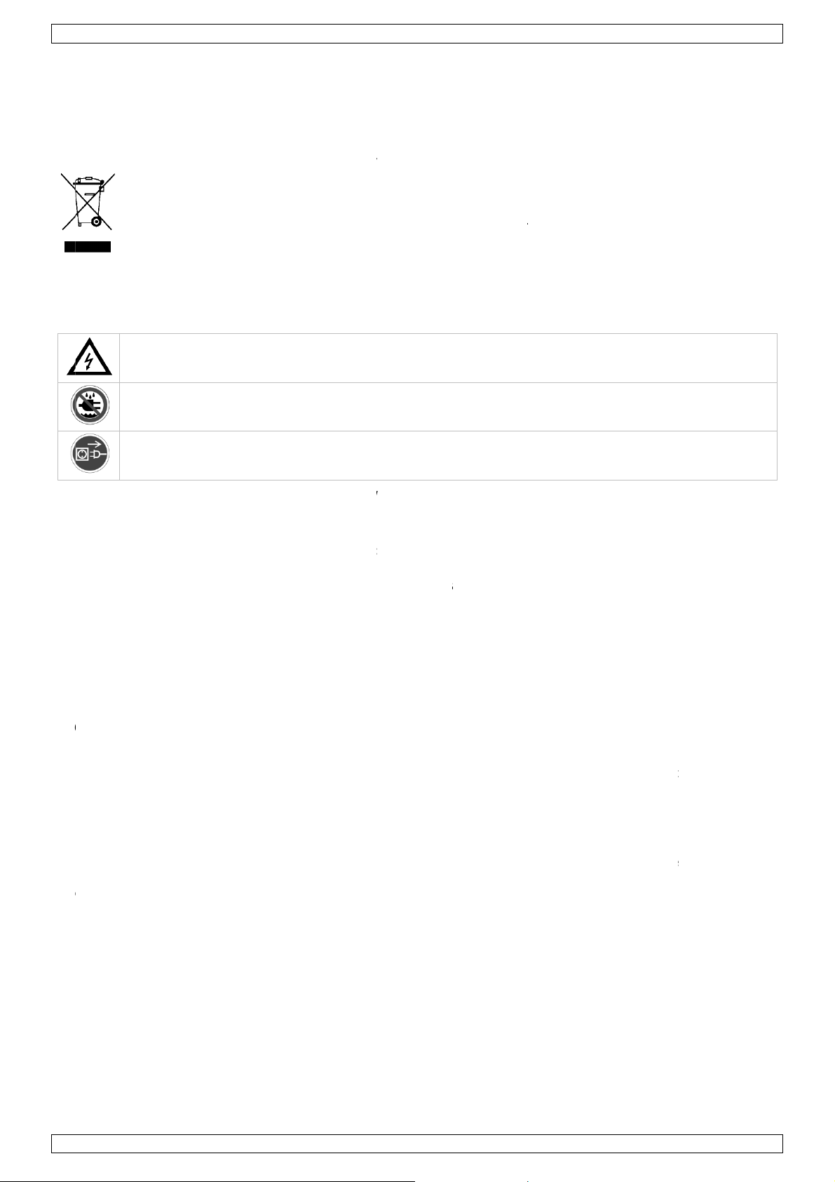
3. TRIM Control
The TRIM control adjusts the input sensitivity (channel gain) of the MIC and LINE inputs
on the mono input channels. This control can be adjusted to accommodate input signals
from a wide variety of sources, from the high outputs from keyboards or drum machines
to the small signal outputs of microphones. This wide range eliminates the need for MIC /
LINE switching. The best S/N balance and dynamic range will be achieved if you adjust
the TRIM control on each channel separately so that the PEAK LED (7) for that channel
lights occasionally.
Note: This control should always be turned fully anticlockwise whenever you connect or
disconnect a signal source to one of the inputs.
4. EQUALIZER Controls
All mono input channels are fitted with three-band EQ. The upper (HIGH) and lower
(LOW) shelving controls have their frequencies fixed at 12 kHz and 80 Hz respectively.
The midrange control has a peaking response, with Q fixed at 2 octaves and the
frequency at 2.5 kHz. All three bands have up to 15 dB of cut and boost with a centre
detent for “off”.
5. AUX / EFF SEND Control
The AUX / EFF controls are mono and post-EQ and post-fader. The signal level sent to
the AUX / EFF bus will be affected by the channel fader setting. The AUX configuration is
ideal for almost all monitoring purpose e.g. for a separate stage monitor mix in live
performances or a studio room monitor in recording applications, such as for a
headphone cue system. The EFF controls the adjustment of level sent by each channel to
the internal DSP (Digital Sound Processor).
6. PAN Control
The channel PAN positions the output of the channel in the stereo field of the Master Mix.
Its constant-power design ensures there are no level discrepancies whether a signal is
hard-panned, centre-stage or somewhere in-between.
7. PEAK Indicator
The PEAK LED illuminates when a channel is going into overload. It detects the peak level
after the EQ and will light at 3 dB before clipping to warn that the signal is approaching
overload. You do not want the PEAK LED to light except very intermittently during a take
or a mix. If it does light persistently, reduce input gain with the TRIM control (3).
8. CHANNEL GAIN Control
The channel GAIN controls determine the output signal level to the master mix bus.
There is no PFL function on the mixer. In order to audition any single channel for proper
gain, you can turn off the gain control of all the other channels (fully anticlockwise) and
set both the auditioned channel and MASTER MIX control (29) to unity gain (0 dB). The
LED OUTPUT meter (21) should read around 0 dB.
STEREO Input Channel (fig. 2)
4. EQUALIZER Controls
The stereo channel EQs operate in the same manner as those in the mono channels. The
left and right signals will be affected equally. A stereo equalizer is generally preferable to
using two mono equalizers when equalizing a stereo signal as it avoids possible
discrepancies between the left and right settings.
5.AUX / EFF SEND Control
These are the same as for the mono channels. Note that a mono sum is taken from the
stereo input.
8. CHANNEL GAIN CONTROL
The channel GAIN controls determine the output signal level to the MASTER MIX bus.
There is no PFL function on the mixer. In order to audition any single channel for proper
gain you can turn off the gain control of all the other channels (fully anticlockwise) and
set both the auditioned channel and MASTER MIX control (29) to unity gain (0 dB). The
LED OUTPUT meter (21) should read around 0 dB.
V. 01 – 30/10/2012 3 ©Velleman nv
Page 4
PROMIX66N/PROMIX88N
9. LINE IN
Each stereo channel has two balanced line level inputs on 1/4" TRS jacks for left and right channels (tip =
positive (+), ring = negative (-), sleeve = ground). If only the connector marked “L” (left) is used, the channel
operates in mono. The stereo channels are designed to handle typical line level signals. The input signals to
these jacks can be either balanced or unbalanced.
10. BAL Control
For a mono input to the L (MONO) input the function of the control is the same as the PAN controls (6) of the
mono channels. However, when a channel is run in stereo, this control functions as a BALANCE control,
determining the relative balance of the left and right channel signals being sent to the left and right MASTER
MIX buses. For example, with the BALANCE control turned fully clockwise, only the right portion of the
channel’s stereo signal will be routed to the MASTER MIX.
MASTER Section (fig. 3 & 4)
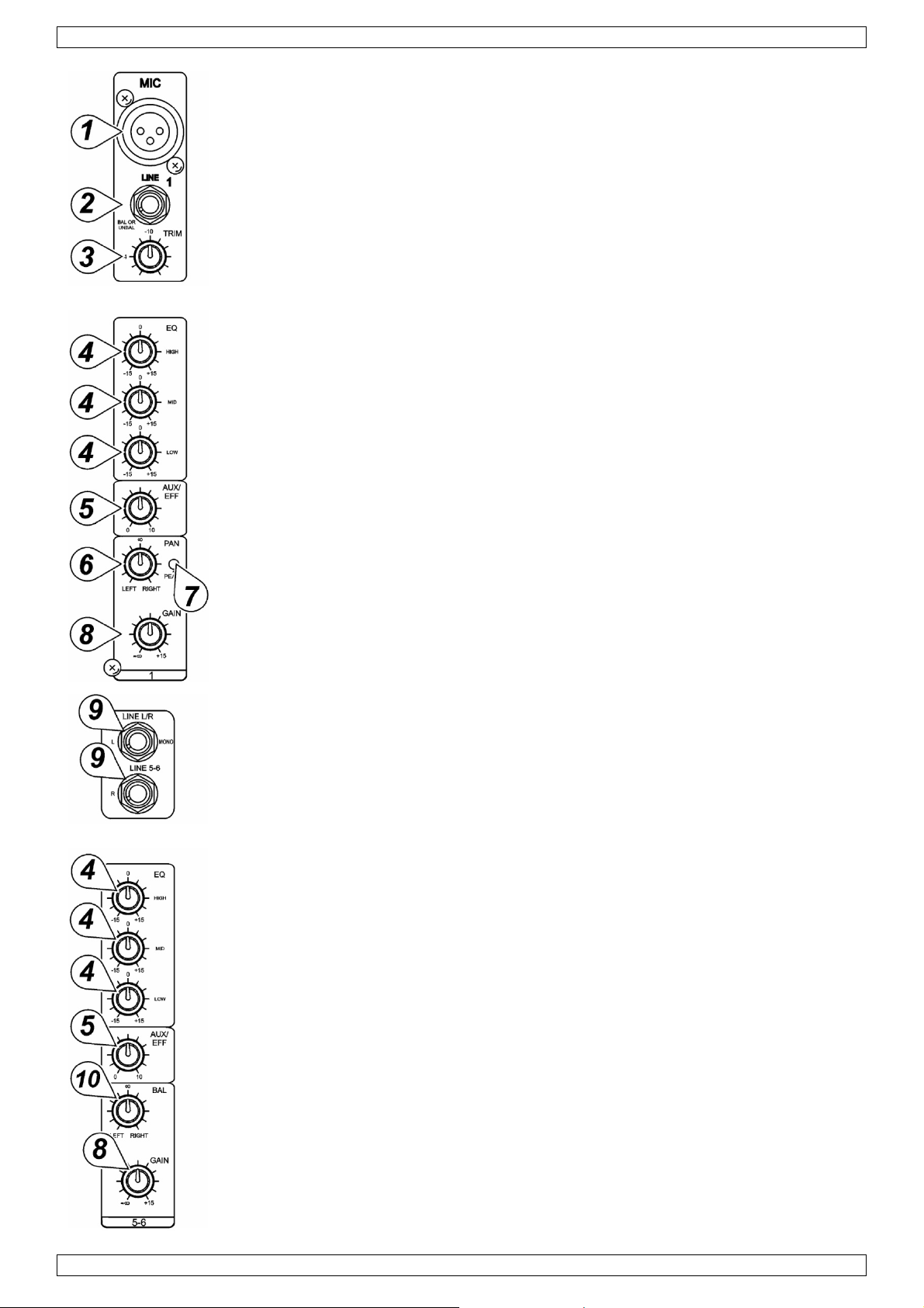
11. STEREO AUX RETURNS (LEFT / MONO, RIGHT)
The AUX RETURN jacks are the mono or stereo returns for AUX SEND. If you connect a signal to the LEFT /
MONO RETURN jack only, the AUX RETURN will operate in mono and the signal will be routed to the AUX
RETURN control (19) and then mixed into the left and right MASTER MIX stereo outputs (13). The separate left
and right return jacks are provided for use with stereo signals such as those from the output of a stereo effects
processor. The left and right return signals will be routed to the AUX RETURN level control (19) and mixed into
the left and right STEREO OUT (13) while maintaining stereo separation.
12. AUX SEND
The AUX SEND is the output for the signal sent from the channel AUX / EFF controls (5) and by the AUX SEND
controls (18) control. They are 1/4" unbalanced phone jacks (tip = positive (+), sleeve = ground). AUX SEND is
a post-fader. These signals can be sent to the input of an effects processor, multi-track recorder, or used for
any other line-level auxiliary purpose.
13. STEREO Outputs
Use these jacks to connect to an external power amplifier if extra output power for a larger PA system is
required. The stereo outputs are left (L) and right (R) unbalanced 1/4" phone jacks, wired as tip = positive (+),
sleeve = ground.
14. TAPE Inputs
These jacks will accept the signal from an external device with a stereo output such as a cassette recorder.
15. REC Outputs
The REC outputs also provide an output of the MASTER MIX. These outputs are RCA jacks and designed
primarily for inputs to tape recorders etc.
16. L-R Control Room Outputs
The L-R control room outputs can be connected to an amp to power stereo control room (or other) monitor
speakers and are 1/4" unbalanced phone jacks, wired as tip = positive (+), sleeve = ground.
V. 01 – 30/10/2012 4 ©Velleman nv
Page 5
PROMIX66N/PROMIX88N
17. PHONES Output
The PHONES output will feed headphones and is a 1/4" TRS jack, wired as tip = left signal, ring = right signal,
sleeve = ground.
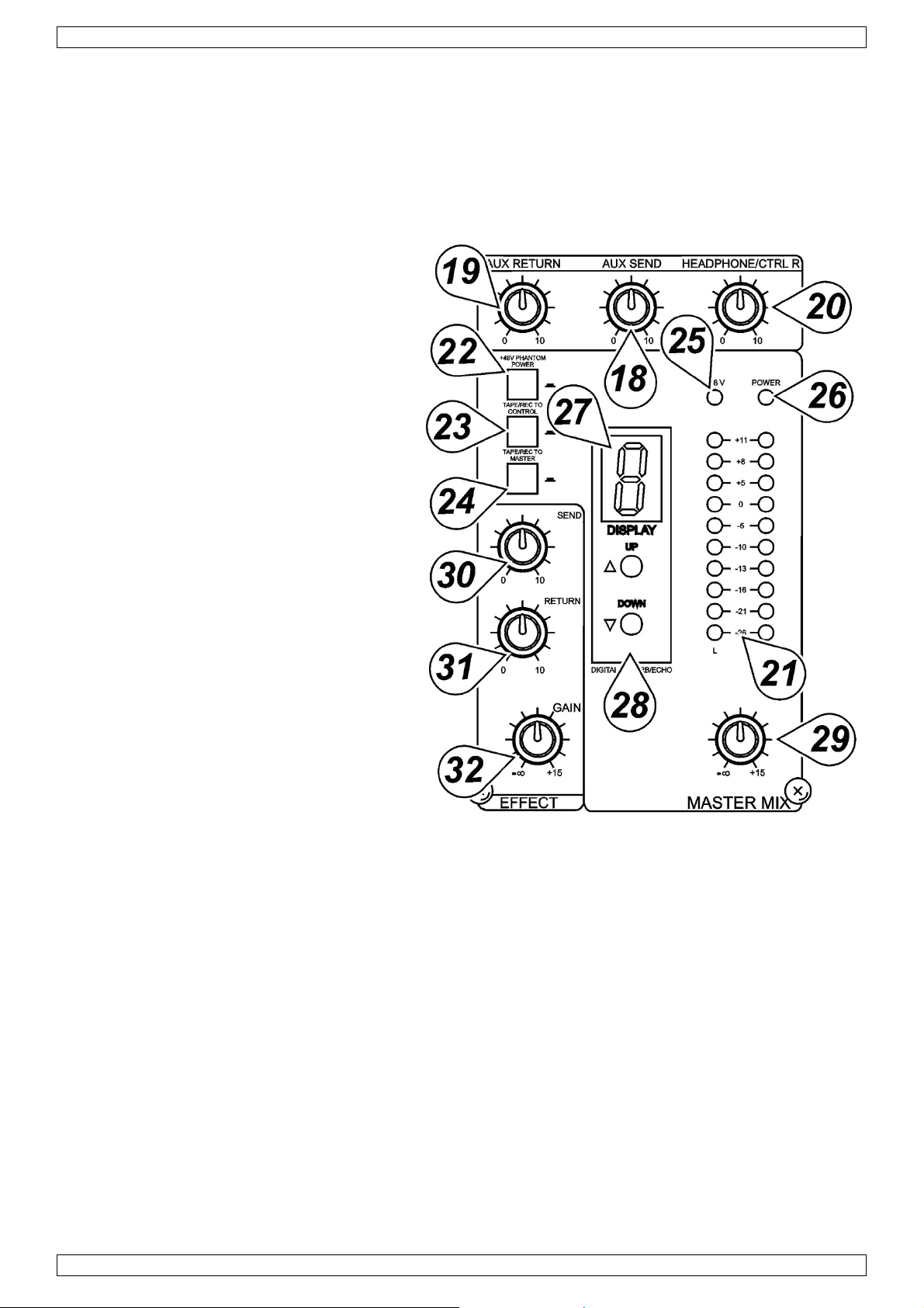
18. AUX SEND
This is a master control that adjusts the output signal level at the AUX SEND (12) jack.
19. AUX RETURN Control
The left and right return signals will be routed to the AUX RETURN level control and mixed into the left and right
stereo OUT (13) while maintaining stereo separation.
20. PHONES/CONTROL ROOM CONTROL
The mixer allows you to monitor the MASTER
MIX. The signal level is adjusted with the
PHONES / CONTROL ROOM control and routed to
both the CONTROL ROOM (16) and
HEADPHONES (17) outputs.
21. LED OUTPUT Meter
The 10-stage LED OUTPUT meter displays the
MASTER MIX output level.
22. PHANTOM POWER ON/OFF Switch
When using condenser microphones, +48 VDC
can be switched globally on or off to the XLR
MIC inputs for all mono channels. When this
switch is in the “ON” position, the PHANTOM
POWER ON LED (25) will light and +48 VDC will
be provided between pins 2 and 3 on all the
mono MIC input XLR connectors. If you do not
need phantom power, be sure to turn this switch
to the “OFF” position.
Note: It is safe to connect balanced dynamic
microphones or line-level devices even if this
switch is on, but connecting unbalanced devices
or devices whose transformers are centregrounded will cause hum or malfunctions.
Shorting the +48 VDC can also damage your
mixer. Also, mute the monitor or PA speakers
first when turning the phantom power on or off.
23. TAPE / REC TO CONTROL ROOM Switch
Use the TAPE / REC TO CONTOL ROOM switch to route signals from the TAPE input (14) to the PHONES /
CONTROL ROOM control (20).
24 TAPE / REC TO MASTER Switch
Use the TAPE / ECHO TO MASTER switch to route signals from the TAPE input (14) to the MASTER MIX GAIN
control (29).
25. PHANTOM POWER LED
The red +48V LED lights up when the phantom power is turned on.
26. POWER ON LED
The red LED indicates that the console is powered on.
DIGITAL EFFECTS Section
27. EFFECTS Display
Press either ECHO effect buttons to scroll in either direction through the 16 presets. The numeric effects display
will indicate which of the 16 effect presets has been selected.
28. ECHO EFFECT SELECT Buttons
The built-in DSP (Digital Sound Processor) offers 16 different preset level and echo intervals selectable by the
echo effect UP / DOWN buttons. The DSP processes the signal on the EFFECTS bus, which is the sum of the
mono and stereo channel inputs controlled by the EFF control (5).
V. 01 – 30/10/2012 5 ©Velleman nv
Page 6
PROMIX66N/PROMIX88N
29. MASTER MIX GAIN Control
The output level routed to the stereo outputs and REC outputs is determined ultimately by the setting of the
MASTER MIX GAIN control.
30. EFFECT SEND
The EFFECT SEND control adjusts the level of the signal on the EFFECTS bus fed to the DSP.
31. EFFECT (ECHO) RETURN
The EFFECT (ECHO) RETURN control adjusts the number of repeats of the echo effect selected with the UP /
DOWN buttons (28).
32. EFFECT GAIN
The EFFECTS GAIN fader controls the signal level sent to the MASTER MIX buses.
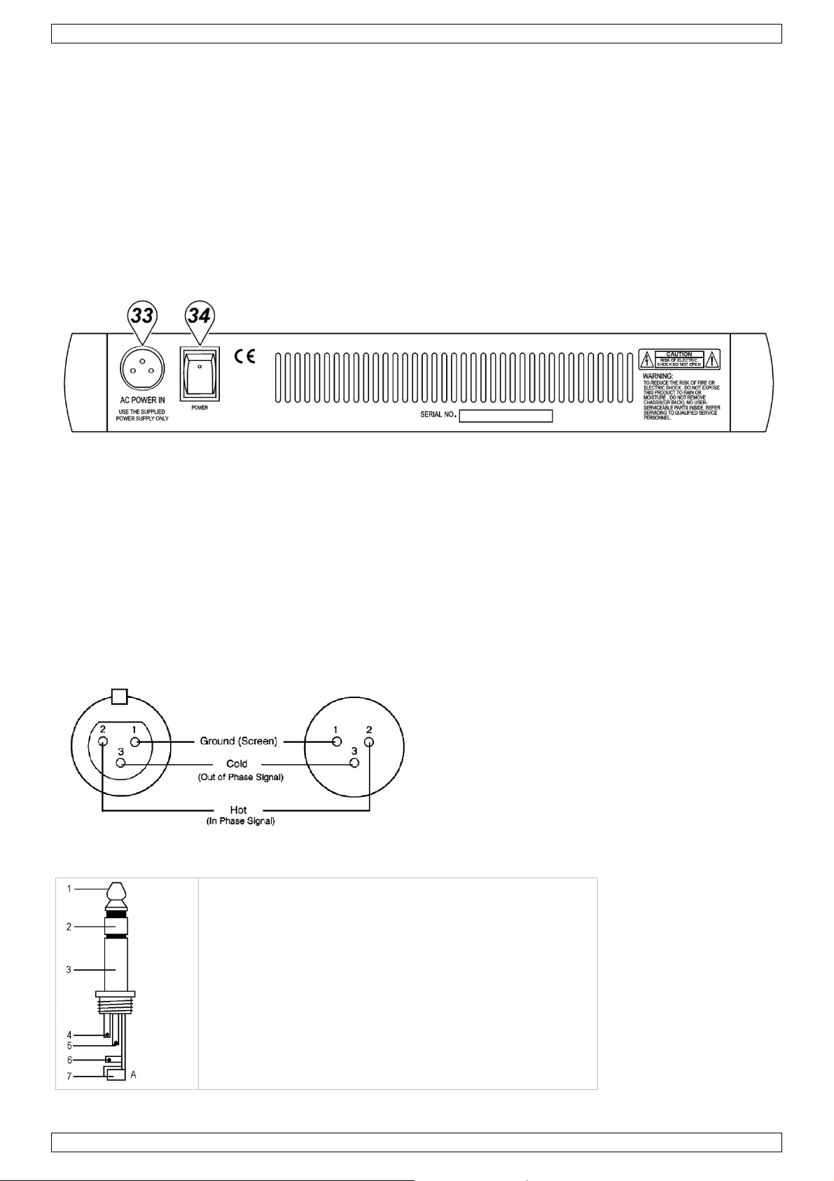
Rear Panel (fig. 5)
33. AC POWER IN Socket
Connect the enclosed power supply to the 3-pin mains connector on the rear of the console. Use the included
adapter to connect the console to the mains.
34. MAIN POWER Switch
This switches the mixer ON or OFF.
Note: Be sure to switch on the power to your mixer before switching on the amplification system.
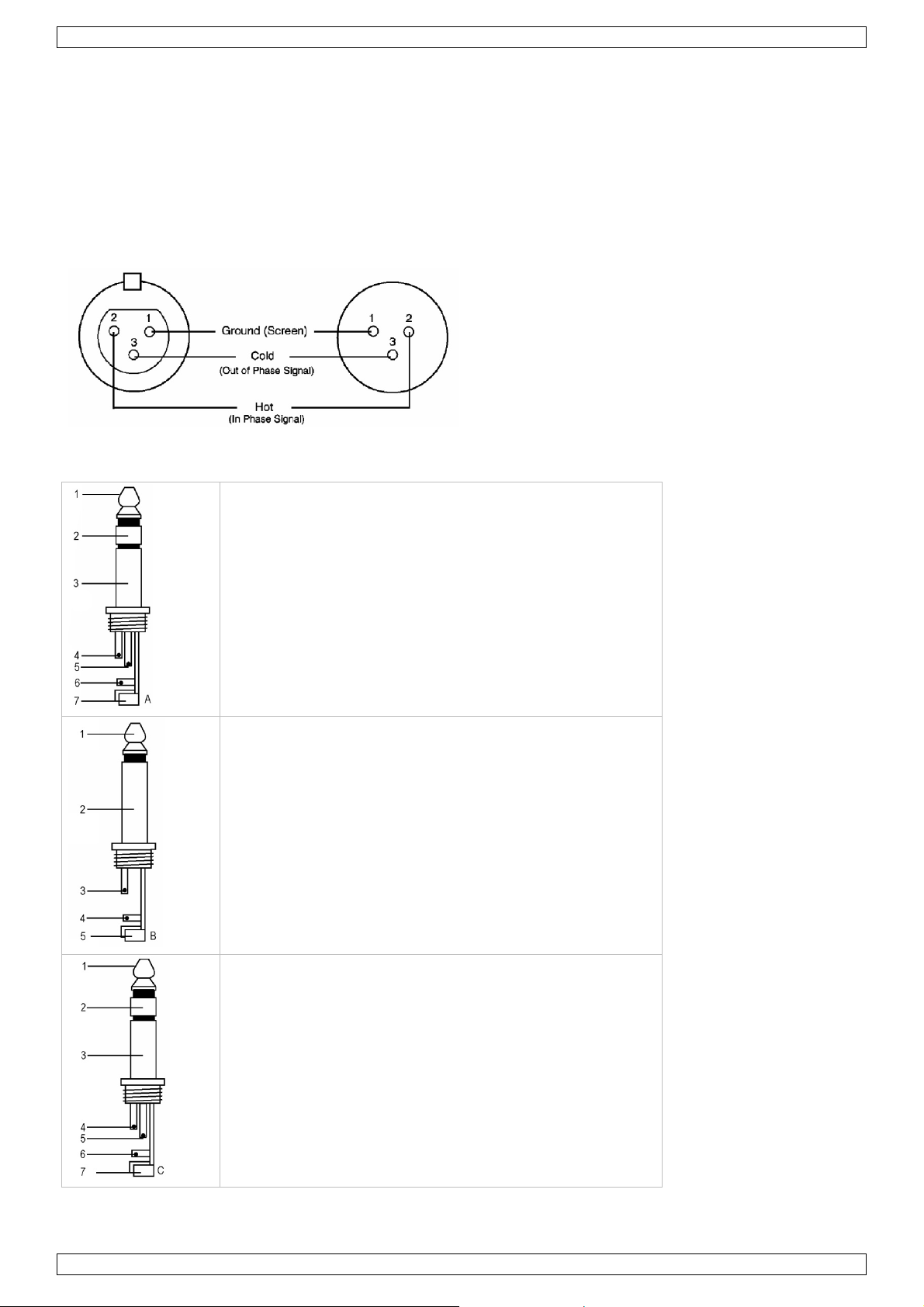
4. Connections
Unbalanced equipment may be connected to balanced inputs/outputs. Either use mono 1/4" jacks or connect
the ring and sleeve of TRS jacks. Never use unbalanced XLR connectors on the MIC input connectors when
using the phantom power supply.
Microphone input Group & mix outputs
Socket (female) Plug (male)
Headphones
1. Tip = left signal
2. Ring = right signal
3. Sleeve = ground
4. Tip
5. Ring
6. Sleeve
7. Strain relief clamp
V. 01 – 30/10/2012 6 ©Velleman nv
Page 7
PROMIX66N/PROMIX88N
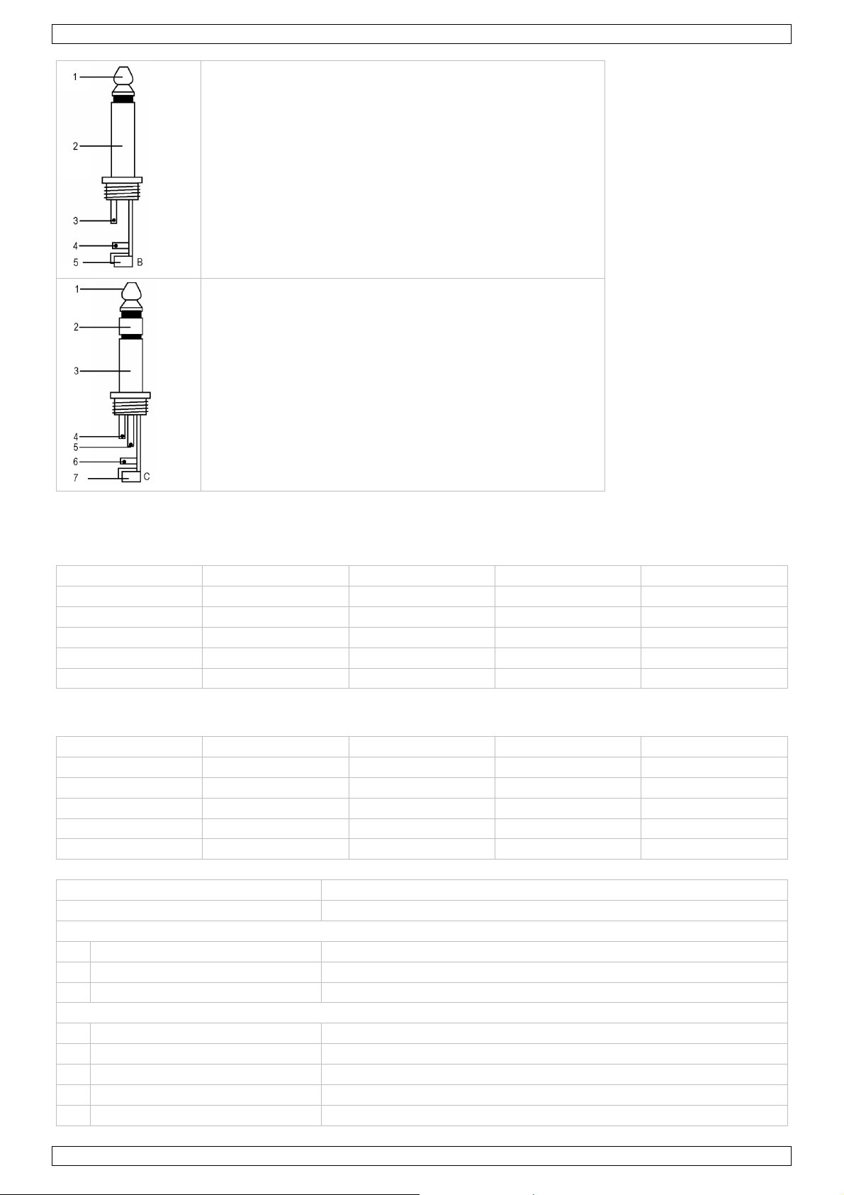
Unbalanced use of mono 1/4" plugs
1. Tip = signal
2. Sleeve = ground
3. Tip
4. Sleeve
5. Strain relief clamp
Balanced use of stereo 1/4" plugs
1. Tip = hot (+)
2. Ring = cold (-)
3. Sleeve = ground
4. Tip
5. Ring
6. Sleeve
7. Strain relief clamp
5. Technical Specifications
Input
Input Connector Input Impedance Nominal Level Max. Level
MONO CH MIC XLR > 1.3 kohm +2 dBm +14 dBm
MONO CH LINE ¼" TRS > 10 kohm +4 dBm +22 dBm
STEREO CH LINE ¼" TRS > 10 kohm +4 dBm +22 dBm
TAPE IN RCA PIN JACKS > 10 kohm +2 dBm +22 dBm
AUX RETURNS ¼" TRS > 10 kohm +4 dBm +22 dBm
Output
Output Connector Input Impedance Nominal Level Max. Level
STEREO OUT L/R ¼" TRS 120 ohm +4 ~ 6 dBm +22 dBm
AUX SEND ¼" TRS 120 ohm +4 ~ 6 dBm +20 dBm
CTRL R OUT ¼" TRS 120 ohm +4 ~ 6 dBm +22 dBm
REC OUT RCA PIN JACKS 1 kohm +4 ~ 6 dBm +22 dBm
PHONES ¼" TRS 100 ohm – 40 mW * 2
Frequency Response 20 Hz to 20 kHz
THD 0.02 %, 20 Hz ~ 20 kHz @ 1 kHz, 0 dBm
Input Channel Equalization
High 12 kHz, +/- 15 dB, Q fixed at 2 octaves
Mid 2.5 kHz, +/- 15 dB, Q fixed at 1 octave
Low 80 Hz, +/- 15 dB, Q fixed at 2 octaves
Gain Control Range
Input Channel Trim Control stop to stop, MIC +10 dB ~ +60 dB; LINE +10 dB ~ +40 dB
Channel/Master/Effect Faders -∞ to +15 dB
Aux Send/Aux Master Send OFF to +15 dB
Aux Return OFF to +20 dB
Channel and Master Effects Send OFF to +15 dB
V. 01 – 30/10/2012 7 ©Velleman nv
Page 8
oHu
U
oDim
e
sof FowwTh
ThNowit
.
aBe
eDa
.
e
n
e
6
8
6
8
r
o
e
t
H
i
e
m
y
g
e
c
g
w
d
g
s
t
r
g
V
s
n
a
a
r
h
b
o
c
e
n
g
a
u
®
s
m
d
s
w
,
h
R
p
r
f
h
n
e
a
h
a
a
i
e
c
X
~
2
t
m
m
m
C
3
9
y
t
c
l
d
R
t
k
e
e
e
g
d
k
=
2
n
h
r
N
a
a
a
g
t
r
a
t
t
e
a
t
w
D
u
e
e
d
a
o
e
a
e
p
r
t
v
o
c
e
w
k
s
d
t
t
i
t
w
v
e
c
e
d
t
g
n
n
i
w
Cr
sstalk @ 1
m and Nois
Equivale
Residual
V
Meters
Ph
antom Pow
Po
wer Supply
C
nsumption
ensions
PROMIX
PROMIX
W
ight
PROMIX
PROMIX
e this devi
U
damage o
r more inf
w.hqpow
e informa
©
COPYRIG
e copyrigh
part of this
hout the pr
kHz
t Input Noi
Output Nois
r
6N
8N
6N
8N
ce with ori
injury res
concerni
r.eu.
ion in this
T NOTICE
t to this m
manual ma
or written c
e
e
ginal acce
ulting fro
g this pro
manual is
nual is o
y be copied
onsent of t
PROMI
-78 dB
20 Hz –
sensitivi
-129 dB
< 90 dB
10-seg
+48 VD
120 VAC
25 W
253 x 2
253 x 2
1.72 kg
2 kg
sories onl
(incorrec
uct and th
ubject to
ned by Ve
reproduce
e copyright
66N/PRO
-68 dB
0 kHz, Rs
y at -60 dB
ent LED x 2
/ 60 Hz or
6 x 55 mm
0 x 55 mm
. Vellema
) use of t
e latest ve
hange wit
leman nv.
, translated
holder.
MIX88N
150 ohm,
30 VAC / 5
nv canno
is device.
sion of thi
hout prior
All world
or reduced
input TRIM
0 Hz select
be held r
s manual,
notice.
ide rights
to any elec
@ 0 dB,
ble
sponsible
lease visi
eserved.
ronic mediu
n the eve
our webs
m or other
t
te
ise
1
Inlei
A
n alle ing
langrijke
H
bt u vrage
nk u voor u
be
schadigd tij
2
Veili
Ra
adpleeg de
Dit s
weg
batt
tere
bren
Wee
elek
Geb
vloei
Trek
niet
ding
zetenen v
ilieu-info
mbool op
eworpen, d
rijen) niet
htkomen v
en. Respe
n, contact
aankoop!
ens het tra
heidsi
voorzichti
roshocks te
uik het toes
stoffen. Pla
de stekker
ebruikt.
elleman
GEB
n de Euro
matie bet
et toestel o
it toestel sc
ij het gewo
or recyclag
teer de pla
er dan de
Lees deze
nsport, inst
structie
bij de inst
vermijden.
tel enkel b
ts geen obj
it het stop
service- e
UIKE
ese Unie
effende di
de verpak
ade kan to
e huishoud
. U moet di
tselijke mili
plaatselijk
andleiding
lleer het da
s
llatie: raak
nnenshuis
cten gevul
ontact (tre
n kwaliteit
SHA
product
ing geeft a
brengen a
elijke afval;
t toestel na
uwetgevin
autoritei
rondig voo
n niet en ra
geen kabels
. Bescherm
met vloeis
niet aan d
sgarantie
DLEI
n dat, als h
n het milie
het moet bi
r uw verdel
.
en betreff
u het toest
dpleeg uw
aan die on
egen regen
of op of na
kabel!) vo
chteraan d
ING
et na zijn le
. Gooi dit t
j een gespe
er of naar e
nd de ver
l in gebrui
dealer.
er stroom
, vochtighei
st het toes
rdat u het
ze handleid
enscyclus
estel (en e
ialiseerd b
n lokaal re
ijdering.
neemt. W
taan om do
en opspat
el.
oestel reini
ing.
ordt
entuele
drijf
yclagepunt
rd het toest
elijke
ende
t en als u h
el
et
V.
01 – 30/10/2
012
8
©Vellema
nv
Page 9

PROMIX66N/PROMIX88N
• De garantie geldt niet voor schade door het negeren van bepaalde richtlijnen in deze handleiding en uw
dealer zal de verantwoordelijkheid afwijzen voor defecten of problemen die hier rechtstreeks verband mee
houden.
• Laat dit toestel installeren en onderhouden door een geschoolde technicus.
• Om beschadiging te vermijden, zet u het toestel best niet aan onmiddellijk nadat het werd blootgesteld aan
temperatuurschommelingen. Wacht tot het toestel op kamertemperatuur gekomen is.
• Houd het toestel uit de buurt van vloeistoffen en plaats geen drank op het mengpaneel.
• Schade door wijzigingen die de gebruiker heeft aangebracht aan het toestel vallen niet onder de garantie.
• Houd dit toestel uit de buurt van kinderen en onbevoegden.
3. Omschrijving
MONO ingangskanaal (zie fig. 1)
1. MIC-ingang
Elk mono ingangskanaal bestaat uit een gebalanceerde microfooningang via de XLR-aansluiting en beschikt
over een schakelende fantoomvoeding (+48 V) voor condensatormicrofoons. De XLR jack-aansluiting is
geconfigureerd voor pin 1 (aarding), pin 2 (positief (+)) en pin 3 (negatief (-)).
2. LINE IN
De LINE-ingang is ontworpen om gebalanceerde en niet-gebalanceerde line-signalen te ontvangen zoals die van
een keyboard, drumcomputer of sampler. Er is voldoende versterking aanwezig op de line-ingang om zelfs
zwakkere signalen zoals die van een ongebalanceerde microfoon of een gitaarsignaal te ontvangen. Wenst u
een gebalanceerd signaal aan de line-ingang te sluiten, bedraad een 1/4" TRS (stereo) plug als volgt: tip
(positief (+)), de ring (negatief (-)) en de huls (aarding).
OPMERKING: U kunt of de MIC-ingang of de LINE-ingang aansluiten. Sluit nooit beide tegelijkertijd op
eenzelfde kanaal.
3. TRIM-regeling
Met de TRIM-regeling regelt u de ingangsgevoeligheid (kanaalversterking) van de MIC-ingang en de LINEingang van de mono ingangskanalen. Regel deze knop zodat u het ingangssignaal van verscheidene bronnen
kunt ontvangen, van de sterke uitgangssignalen ven een keyboard of drumcomputer tot de zwakke signalen
van een microfoon. Het grote bereik maakt MIC / LINE-schakeling overbodig. De beste S/R-verhouding en
dynamisch bereik verkrijgt u wanneer u de TRIM-regeling op elk kanaal afzonderlijk regelt zodanig dat de PEAK
LED (7) maar af en toe oplicht.
OPMERKING: Draai deze regelknop volledig naar links voordat u een signaal aansluit of ontkoppelt.
4. EQUALIZER
Alle mono ingangskanalen beschikken over een driebands equalizer. De bovenste (HIGH) en onderste (LOW)
potmeters hebben een frequentie van 12 kHz respectievelijk 80 Hz. De regelknop voor de middentonen heeft
een piekrespons met een Q van 2 octaven en een frequentie van 2.5 kHz. Alle drie banden hebben tot 15 dB
versterking of verzwakking met een centernok voor “off”.
5. AUX / EFF SEND
De AUX / EFF-regelknoppen zijn mono, post-EQ en post-fader. Het signaalniveau dat naar de AUX / EFF-bus
wordt gezonden, zal beïnvloed worden door de instelling van de fader. De AUX-configuratie is ideaal voor bijna
elke monitoring, bvb. een afzonderlijke geluidsregeling van de podiummonitor tijdens een live-optreden of een
geluidsregeling in een studio tijdens een opname zoals voor een hoofdtelefoon. De EFF regelt het niveau dat
elke kanaal naar de interne DSP (Digital Sound Processor) zendt.
6. PAN-regeling
De PAN-regeling plaatst de uitgang van een kanaal in het stereobeeld van de mix. Het toestel zorgt ervoor dat
er zich geen discrepanties in het niveau voorkomen, of een signaal nu langs een kant, centraal of ergens
tussenin staat.
7. PEAK-aanduiding
De PEAK-aanduiding licht op wanneer een kanaal overstuurt. Het toestel neemt een piek waar na de EQ, licht
op 3 dB voor de vervorming en waarschuwt u wanneer het signaal wordt overstuurd. Zorg dat de PEAKaanduiding niet oplicht uitgenomen af en toe tijdens een mix. Licht de aanduiding op een constante basis,
verminder de ingangsversterking door middel van de TRIM-regeling (3).
8. CHANNEL GAIN-regeling
De GAIN-regeling bepaalt het niveau van het uitgangssignaal naar de master mix bus. De mengtafel is niet
voorzien van een PFL-functie. Om elk apart kanaal op versterking te testen, draai de gain-knop van alle andere
V. 01 – 30/10/2012 9 ©Velleman nv
Page 10

PROMIX66N/PROMIX88N
kanalen toe (naar links) en stel de regelknop van zowel het gewenste kanaal als die van de MASTER MIX (29)
op nulversterking (0 dB). De LED-meter (21) zou 0 dB moeten aanwijzen.
STEREO ingangskanaal (fig. 2)
4. EQUALIZER
De equalizer van de stereo kanalen werken zoals de equalizer van de mono kanalen. De linkse en de rechtse
signalen worden op dezelfde manier beïnvloed. Gebruik eerder een stereo equalizer dan twee mono equalizers
wanneer u een stereo signaal wenst te mixen. Zo vermijdt u mogelijke discrepanties tussen de linkse en de
rechtse instellingen.
5. AUX / EFF SEND
Identiek als de mono kanalen. Een mono som wordt van de stereo ingang genomen.
8. CHANNEL GAIN-regeling
De GAIN-regeling bepaalt het niveau van het uitgangssignaal naar de master mix bus. De mengtafel is niet
voorzien van een PFL-functie. Om elk apart kanaal op versterking te testen, draai de gain-knop van alle andere
kanalen toe (naar links) en stel de regelknop van zowel het gewenste kanaal als die van de MASTER MIX (29)
op nulversterking (0 dB). De LED-meter (21) zou 0 dB moeten aanwijzen.
9. LINE IN
Elk stereokanaal beschikt over twee gebalanceerde LINE-ingangen langs 1/4" TRS jack-aansluitingen voor het
linkse en het rechtse kanaal (tip = positief (+), ring = negatief (-), huls = aarding). Gebruikt u enkel de
aansluiting “L” (links), dan werkt het kanaal in mono. De stereokanalen zijn ontworpen om typische signalen
aan te pakken. De ingangssignalen naar deze jack-aansluitingen kunnen gebalanceerd of niet-gebalanceerd
zijn.
10. BAL-regeling
Deze regeling werkt op dezelfde manier als de PAN-regeling (6) voor een mono-ingang naar de L (MONO)
ingang. Wanneer een kanaal echter in stereo functioneert, dan werkt deze knop als een balansregeling tussen
het linker- en rechterkanaal. Voorbeeld: Draai de BAL-regeling volledig naar rechts om enkel het rechtse
gedeelte van een stereosignaal hoorbaar te maken.
MASTER-gedeelte (zie fig. 3 & 4)
11. STEREO AUX RETURNS (LEFT / MONO, RIGHT)
De AUX RETURN-aansluitingen zijn de mono of stereo retours voor de AUX SEND. Wanneer u een signaal enkel
koppelt aan de LEFT / MONO RETURN-aansluiting, dan zal de AUX RETURN in mono functioneren en het signaal
naar de AUX RETURN-regeling (19) gestuurd worden waarna het wordt gemixt in de links en rechtse MASTER
MIX stereo-uitgangen (13). De afzonderlijke linkse en rechtse retouraansluitingen zijn meegeleverd zodat u
stereosignalen zoals deze van een stereo effectprocessor kunt gebruiken. De linkse en rechtse signalen worden
naar de AUX RETURN-regeling (19) gestuurd en gemixt in de linkse en rechtse STEREO OUT (13) terwijl er nog
steeds stereoscheiding aanwezig is.
12. AUX SEND
De AUX SEND is een uitgang voor het signaal afkomstig van de AUX / EFF-regeling (5) en gezonden door de
AUX SEND-regeling (18). Deze zijn niet-gebalanceerde 1/4" phone-pluggen (tip = positief (+), huls = aarding).
AUX SEND is een post fader. Deze signalen kunnen worden gezonden naar de ingang van een effectprocessor,
multi-track recorder of gebruikt worden met een aangesloten line-level toestel.
13. STEREO-uitgangen
Gebruik deze jackaansluitingen om de externe versterker aan te sluiten wanneer u extra vermogen nodig hebt
voor een groter PA-systeem. De stereo uitgangen zijn links (L) en rechts (R) niet-gebalanceerde 1/4" Phonepluggen, met tip = positief (+), huls = aarding.
14. TAPE-ingangen
Deze jacks ontvangen het signaal van een externe toestel met stereo uitgang zoals een cassetterecorder.
15. REC-uitgangen
De REC-uitgangen leveren een uitgang voor de MASTER MIX. Deze uitgangen zijn van het RCA-type en zijn
ontworpen als ingangen voor bandrecorders enz.
16. L-R Control Room
Deze uitgangen kunnen aan een versterker worden aangesloten om stereo monitors (of andere) te voeden. De
uitgangen zijn niet-gebalanceerde 1/4" phone-pluggen met tip = positief (+), huls = aarding.
17. PHONES
De PHONES-uitgang voedt de hoofdtelefoon en is een 1/4" TRS jack, met tip = links signaal, ring = rechts
signaal, huls = aarding.
V. 01 – 30/10/2012 10 ©Velleman nv
Page 11

PROMIX66N/PROMIX88N
18. AUX SEND
Dit is een master-regeling waarmee u het niveau van het uitgangssignaal kunt regelen aan de AUX SEND (12)
jack.
19. AUX RETURN
De linkse en rechtse retoursignalen worden naar de AUX RETURN gezonden en gemixt in een links en een
rechts STEREO OUT (13) terwijl er nog steeds stereoscheiding aanwezig is.
20. PHONES/CONTROL ROOM CONTROL
Met de mengtafel kunt u de MASTER MIX controleren. Het signaalniveau wordt met PHONES / CONTROL ROOM
geregeld en verzonden naar zowel de CONTROL ROOM (16) en de HEADPHONES (17).
21. LED OUTPUT
De 10-traps LED OUTPUT-meter geeft het uitgangsniveau van de MASTER MIX weer.
22. FANTOOMVOEDING ON/OFF
Gebruikt u condensatormicrofoons, dan kunt u +48 VDC in- of uitschakelen. Wanneer de schakelaar op “ON”
staat, dan licht de LED van de FANTOOMVOEDING (25) op en pinnen 2 en 3 van alle mono XLR
microfooningangen worden voorzien van een spanning van +48 VDC. Hebt u geen fantoomvoeding nodig,
plaats de schakelaar dan op “OFF”.
OPMERKING: U kunt gerust gebalanceerde dynamische microfoons of line level toestellen aansluiten, ook al
staat deze schakelaar op “ON”. Sluit u niet-gebalanceerde toestellen of toestellen met een transformator met
centrale aarding aan, dan kan dit brom of een slechte werking veroorzaken. Een kortsluiting van de +48 VDC
kan eveneens uw mengtafel beschadigen. Demp eerst de monitors of de PA-luidsprekers alvorens de
fantoomvoeding van uw mengtafel aan of uit te schakelen.
23. TAPE / REC TO CONTROL ROOM
Gebruik deze schakelaar om de signalen van de TAPE-uitgang (14) naar de PHONES / CONTROL ROOM (20) te
zenden.
24. TAPE / REC TO MASTER
Gebruik deze schakelaar om de signalen van de TAPE-ingang (14) naar de MASTER MIX GAIN (29) te zenden.
25. FANTOOM VOEDINGLED
De rode LED licht op wanneer de fantoomvoeding in- of uitgeschakeld wordt.
26. VOEDINGLED
De rode LED geeft weer of de tafel in- of uitgeschakeld is.
DIGITALE EFFECTEN
27. EFFECT-weergave
Druk op een ECHO effectknop om door de 16 voorkeuzeprogramma’s te rollen. De numerieke display geeft
weer welke van de 16 voorkeuzeprogramma’s is geselecteerd.
28. ECHO EFFECT keuzeknoppen
De ingebouwde DSP (Digital Sound Processor) biedt 16 verschillende echo-instellingen die met de UP / DOWNknoppen kunnen worden geselecteerd. De DSP verwerkt het signaal op de EFFECTS-bus, het geheel van de
mono en stereo-ingangen, die door EFF (5) kan bijgeregeld worden.
29. MASTER MIX GAIN
Het uitgangsniveau dat naar de stereo uitgangen en REC-uitgangen is verzonden, wordt uiteindelijk bepaald
door de regeling van MASTER MIX GAIN.
30. EFFECT SEND
Hiermee regelt u het signaalniveau op de EFFECT-bus naar de DSP.
31. EFFECT (ECHO) RETURN
De EFFECT (ECHO) RETURN regelt het aantal herhalingen van de echo die u met de UP / DOWN-knoppen (28)
heeft geselecteerd.
32. EFFECT GAIN
Met de EFFECTS GAIN fader regelt u het signaalniveau naar de MASTER MIX-bussen.
Achterpaneel (zie fig. 5)
33. AC-voedingsingang
Verbind de meegeleverde voeding met de 3-pin aansluiting achteraan het toestel. Gebruik enkel de
meegeleverde adapter.
V. 01 – 30/10/2012 11 ©Velleman nv
Page 12
PROMIX66N/PROMIX88N
34. VOEDINGSSCHAKELAAR
Schakel de mengtafel in- of uit.
OPMERKING: Schakel eerst uw mengtafel in alvorens de luidsprekers in te schakelen.
4. Aansluitingen
U mag niet-gebalanceerde toestellen met de gebalanceerde in- of uitgangen verbinden. Gebruik mono 1/4"
jack-aansluitingen of verbind de ring en de huls van de TRS jack-aansluitingen. Gebruik nooit nietgebalanceerde XLR-aansluitingen met de MIC-ingangen wanneer u de fantoomvoeding gebruikt.
Microfooningang Groep- & mixuitgangen
Doos (vrouwelijk) Plug (mannelijk)
Hoofdtelefoon
1. Tip = signaal links
2. Ring = signaal rechts
3. Huls = aarding
4. Tip
5. Ring
6. Huls
7. Snoerontlastingsklem
Niet-gebalanceerde mono 1/4" pluggen
1. Tip = signaal
2. Huls = aarding
3. Tip
4. Huls
5. Snoerontlastingsklem
Gebalanceerde stereo 1/4" pluggen
1. Tip = hot (+)
2. Ring = cold (-)
3. Huls = aarding
4. Tip
5. Ring
6. Huls
7. Snoerontlastingsklem
V. 01 – 30/10/2012 12 ©Velleman nv
Page 13

PROMIX66N/PROMIX88N
5. Technische specificaties
Ingang
Ingang Connector Ingangsimpedantie Nominaal niveau Max. niveau
MONO CH MIC XLR > 1.3 kohm +2 dBm +14 dBm
MONO CH LINE ¼" TRS > 10 kohm +4 dBm +22 dBm
STEREO CH LINE ¼" TRS > 10 kohm +4 dBm +22 dBm
TAPE IN RCA PIN JACKS > 10 kohm +2 dBm +22 dBm
AUX RETURNS ¼" TRS > 10 kohm +4 dBm +22 dBm
Uitgang
Uitgang Connector Ingangsimpedantie Nominaal niveau Max. niveau
STEREO OUT L/R ¼" TRS 120 ohm +4 ~ 6 dBm +22 dBm
AUX SEND ¼" TRS 120 ohm +4 ~ 6 dBm +20 dBm
CTRL R OUT ¼" TRS 120 ohm +4 ~ 6 dBm +22 dBm
REC OUT RCA PIN JACKS 1 kohm +4 ~ 6 dBm +22 dBm
PHONES ¼" TRS 100 ohm – 40 mW * 2
Frequentierespons 20 Hz tot 20 kHz
THD 0.02 %, 20 Hz ~ 20 kHz @ 1 kHz, 0 dBm
Equalizer ingangskanaal
High 12 kHz, +/- 15 dB, Q vast op 2 octaven
Mid 2.5 kHz, +/- 15 dB, Q vast op 1 octaaf
Low 80 Hz, +/- 15 dB, Q vast op 2 octaven
Versterkingsbereik
Trim-regeling ingangskanaal stop tot stop, MIC +10 dB ~ +60 dB; LINE +10 dB ~ +40 dB
Channel/Master/Effect Faders -∞ to +15 dB
Aux Send/Aux Master Send OFF tot +15 dB
Aux Return OFF tot +20 dB
Channel en Master Effects Send OFF tot +15 dB
Crosstalk @ 1 kHz -78 dB ~ -68 dB
Brom en ruis 20 Hz – 20 kHz, Rs = 150 ohm, input TRIM @ 0 dB,
gevoeligheid @ -60 dB
Equivalent ingangsruis -129 dBm
Uitgangsruis < 90 dBm
VU-meters 10-segment LED x 2
Fantoomvoeding +48 VDC
Voeding 120 VAC / 60 Hz of 230 VAC / 50 Hz selecteerbaar
Verbruik 25 W
Afmetingen
PROMIX66N 253 x 236 x 55 mm
PROMIX88N 253 x 290 x 55 mm
Gewicht
PROMIX66N 1.72 kg
PROMIX88N 2 kg
Gebruik dit toestel enkel met originele accessoires. Velleman nv is niet aansprakelijk voor schade of
kwetsuren bij (verkeerd) gebruik van dit toestel.
Voor meer informatie over dit product en de laatste versie van deze handleiding, zie
www.hqpower.eu.
De informatie in deze handleiding kan te allen tijde worden gewijzigd zonder voorafgaande
kennisgeving.
V. 01 – 30/10/2012 13 ©Velleman nv
Page 14

VeHe
c
.
uDe
n
o
p
.
.
a
Ch
s
n2. L’eceu
b
n(poRE
R
g
o
e
o
s
t
y
e
o
e
e
m
a
s
e
t
s
u
r
e
n
e
u
É
x
t
c
t
C
d
m
a
s
a
a
o
n
o
n
s
e
n
v
t
e
o
r
s
p
p
d
q
n
t
a
u
a
o
6
N
n
b
e
o
a
t
g
e
h
e
r
n
p
x
s
a
t
m
j
e
e
e
q
e
X
e
e
a
p
t
t
r
X
e
d
E
a
e
v
s
c
t
j
n
é
é
é
a
e
i
e
m
u
e
n
n
m
â
’
i
n
M
e
e
t
u
c
t
l
t
n
n
o
n
r
a
a
d
p
(
é
a
c
E
e
v
d
p
n
é
c
e
o
e
i
p
e
l
é
o
l
s
n
h
y
e
1
p
k
r
t
c
u
u
p
q
u
m
’
f
o
m
o
m
e
s
e
r
e
c
e
c
t
s
d
o
i
o
q
t
u
a
n
e
s
o
n
s
t
s
e
©
AUTEURS
lleman nv
t is niet toe
be
werken en
re
hthebbend
ECHT
heeft het
estaan om
p te slaan
.
uteursrec
deze handl
p een elekt
PROMI
t voor dez
iding of ge
onisch med
66N/PRO
handleid
eelten erva
ium zonder
MIX88N
ng. Alle w
over te ne
oorafgaan
reldwijde
men, te ko
e schriftelij
rechten v
iëren, te ve
e toestem
orbehoud
talen, te
ing van de
n.
1
Intr
A
x résident
s informa
E
cas de qu
N
us vous re
l’a
pareil. Si l’
2
Con
Se
référer à la
•
La garanti
votre reve
•
Confiez l'i
•
Ne branch
attendez j
vitez d’e
•
l’appareil.
Les domm
•
Gardez vo
•
Ce s
pollu
parm
Renv
resp
Soy
mor
Utili
d’ea
Déb
l'app
duction
de l'Unio
ions envir
mbole sur l'
r l'environ
i les déchet
yer les équ
cter la régl
stions, co
ercions de
ppareil a é
ignes d
z prudent l
els.
er cet appa
. Ne jamai
ancher l’ap
areil ; non
garantie
ne s'appli
ndeur décli
stallation e
z pas l'app
squ’à ce q
poser l’app
ages occasi
re PROMIX
europée
nnementa
appareil ou
ement. Ne
municipau
ipements u
mentation l
tacter les
otre achat
é endomm
sécuri
rs de l'insta
eil unique
placer d’ob
areil s’il n’e
as le câble.
e service
ue pas aux
era toute r
l’entretien
reil après
e l'appareil
reil à des li
nnés par d
6N/PROMI
MOD
ne
les import
l'emballage
as jeter un
non sujets
agés à votr
ocale relati
autorités l
! Lire la pré
gé pendant
é
llation : tou
ent à l'in
et contena
st pas utilis
t de qualit
dommages
sponsabilit
à un person
xposition à
ait atteint l
uides et v
s modificat
88N hors d
D’E
ntes conc
indique que
appareil él
au tri sélec
fournisse
e à la prote
ocales pou
ente notice
le transpor
her un câb
érieur. Pro
t un liquide
ou pour le
Vellema
survenus e
pour les pr
nel qualifié.
des variatio
températu
illez à ne pl
ons à l'app
la portée
PLOI
rnant ce
l’éliminatio
ctrique ou
if ; une dé
r ou à un s
tion de l’en
r éliminati
attentivem
, ne pas l’in
e sous tens
éger de la
sur l’appar
nettoyer. Ti
® en fin de
négligeant
blèmes et
s de temp
e ambiante
cer aucun
reil par le c
e personne
roduit
d’un appa
lectronique
hèterie trai
rvice de re
vironnemen
n.
nt avant la
staller et co
on peut ca
luie, de l’h
il.
rer la fiche
notice.
certaines di
es défauts
rature. Afin
avant de l'
bjet conten
ient, ne to
non qualifi
eil en fin d
(et des pile
era l’appar
yclage local
t.
mise en se
nsulter votr
ser des éle
midité et d
our débran
rectives de
ui en résul
d’éviter de
tiliser.
ant un liqui
bent pas s
ées et de je
vie peut
éventuelle
il en questi
. Il convient
vice de
revendeur
trochocs
s projectio
cher
ette notice
ent.
dommage
e sur
us la garan
nes enfant
)
n.
de
.
s
et
,
ie.
.
3
Des
C
nal d’en
1.
Entrée MI
aque canal
di
pose d’une
co
figurée co
LINE IN
ntrée LINE
x d’un clav
y
rancher de
co
necter un
sitif (+)), l
MARQUE :
de
ux canaux s
V.
01 – 30/10/2
ription
rée MO
’entrée mo
alimentatio
me suit :
été conçu
ier, d’un m
faibles sign
ignal symé
bague (né
Ne connect
imultanéme
012
O (voir i
no offre un
fantôme d
roche 1 (m
pour acce
dule de bat
ux comme
rique à l’en
atif (-)) et
z que l’ent
nt.
ll. 1)
entrée sy
+48 V po
sse), broch
ter des sig
erie électro
ceux d’un
rée LINE, c
le manche (
ée MIC ou l
étrique pou
r des micro
2 (positif
aux à nivea
ique ou d’
icrophone
blez une fi
masse).
entrée LIN
14
r microphon
hones à co
+)) et broc
u en ligne s
chantillonn
symétrique
he TRS de
d’un canal.
e à partir d
densateur.
e 3 (négati
métriques
urs. Il y a s
ou d’une gu
/4" TRS co
Ne connect
une connex
La connexi
(-)).
u asymétri
uffisammen
itare. Si vo
me suit : l
ez jamais le
on XLR et
n XLR est
ues comm
de gain po
s désirez
pointe
s deux aux
©Vellema
ur
nv
Page 15

PROMIX66N/PROMIX88N
3. Réglage TRIM
Le réglage TRIM ajuste la sensibilité à l’entrée (le gain du canal) des entrées MIC et LINE sur les canaux
d’entrée mono. Il est possible de régler de telle façon à accepter des signaux d’entrée de sources diverses, du
signal fort d’un clavier ou d’un module de batterie électronique au signal faible d’un microphone. Cette étendue
élimine la commutation MIC / LINE. Vous obtiendrez le meilleur rapport S/B et étendue dynamique en réglant le
TRIM de chaque canal séparément de manière à ce que la LED DE SURCHARGE (« PEAK ») (7) du canal ne
s’illumine que occasionnellement.
REMARQUE : Positionnez ce réglage complètement à gauche lors de la (dé)connexion d’une source de signal.
4. Les ÉGALISEURS
Tous les canaux d’entrée mono sont munis d’une égalisation 3 bandes. Les potentiomètres supérieur (HIGH) et
inférieur (LOW) on tune fréquence de 12 kHz et de 80 Hz respectivement. Le potentiomètre des moyens a une
réponse en crête, avec un Q fixé à 2 octaves et une fréquence de 2.5 kHz. Les trois bandes ont une intensité
d’augmentation et de diminution jusqu’à 15 dB avec un déclic central pour « off ».
5. AUX / EFF SEND
Les potentiomètres AUX / EFF sont des réglages mono et post-EQ et post-fader. Le niveau du signal envoyé au
bus AUX / EFF sera influencé par le réglage du fader du canal. La configuration AUX est idéale pour la balance
de p.ex. les retours de scène lors d’un concert en direct ou d’un retour de studio lors d’un enregistrement en
studio comme des écouteurs. L’EFF règle le niveau envoyé par chaque canal vers le DSP (Digital Sound
Processor, c.à.d. le processeur de traitement des signaux audionumériques) interne.
6. PAN
Le PAN positionne le signal de sortie du canal dans le champ stéréo du mixage général. Ses spécifications
éliminent les décalages de niveau de volume, qu’il soit situé sur un côté, au centre ou entre-deux.
7. LED de SURCHARGE (PEAK)
La LED de SURCHARGE (PEAK) s’illumine dès que le canal atteint la surcharge. Il détecte le niveau de crête
après l’EQ et la LED s’illumine à partir de 3 dB avant la saturation pour avertir que le signal approche la
surcharge. Veillez à ce que la LED ne s’illumine pas excepté de manière intermittente pendant une prise ou le
mixage. Si la LED s’illumine régulièrement, diminuez le gain d’entrée avec le potentiomètre TRIM (3).
8. GAIN du canal
Le potentiomètre du GAIN détermine le niveau du signal de sortie vers le bus de mixage maître. La table de
mixage n’est pas munie de la fonction PFL. Pour régler le gain de chaque canal, tournez le gain de tous les
autres canaux complètement vers la gauche et placez le canal et le MASTER MIX (29) à gain unitaire (0 dB).
L’échelle à LED (21) doit afficher aux alentours de 0 dB.
Canal d’entrée STÉRÉO (voir ill. 2)
4. Les ÉGALISEURS
Les égaliseurs du canal stéréo fonctionnent identiquement à ceux du canal mono. Les signaux de gauche et de
droite seront influencés de manière égale. Il est préférable d’utiliser une égalisation stéréo à deux égalisations
mono lors de l’égalisation d’un signal stéréo pour éviter des décalages entre le réglage gauche et celui de
droite.
5. AUX / EFF SEND
Identique à ceux du canal mono. Une somme mono est reprise à partir de l’entrée stéréo.
8. GAIN du canal
Le potentiomètre du GAIN détermine le niveau du signal de sortie vers le bus de mixage maître. La table de
mixage n’est pas munie de la fonction PFL. Pour régler le gain de chaque canal, tournez le gain de tous les
autres canaux complètement vers la gauche et placez le canal et le MASTER MIX (29) à gain unitaire (0 dB).
L’échelle à LED (21) doit afficher aux alentours de 0 dB.
9. LINE IN
Chaque canal stéréo est muni de deux entrées à niveau en ligne symétriques en forme de prise TRS 1/4" pour
les canaux de gauche et de droite (la pointe = positif (+), la bague = négatif (-), le manche = masse). Si vous
n’utilisez que la connexion marquée « L » (left ou gauche), le canal opère en mono. Les canaux stéréo ont été
conçus pour accepter des signaux à niveau en ligne typiques. Les signaux d’entrée sont soit symétriques soit
asymétriques.
10. BAL
Cette fonction est identique aux réglages PAN (6) des canaux mono si vous connecter un signal mono à l’entrée
L (MONO). Cependant, si un canal fonctionne en stéréo, ce réglage fonctionne de manière identique au réglage
BALANCE, déterminant la balance relative entre les signaux de gauche et de droite routés vers les bus MASTER
de gauche et de droite. Exemple : avec le réglage BALANCE complètement vers la droite vous routerez
uniquement la partie de droite d’un signal stéréo vers le MASTER MIX.
V. 01 – 30/10/2012 15 ©Velleman nv
Page 16

PROMIX66N/PROMIX88N
Section MASTER (voir ill. 3 & 4)
11. STEREO AUX RETURNS (LEFT / MONO, RIGHT)
Les connexions AUX RETURN sont les retours mono ou stéréo des AUX SEND. En connectant un signal au LEFT /
MONO uniquement, le AUX RETURN fonctionnera en mono et le signal sera routé vers le réglage AUX RETURN
(19) et mixé dans les sorties stéréo MASTER MIX de gauche et de gauche (13). Utilisez les retours de gauche et
de droite avec des signaux stéréo comme ceux d’un processeur d’effets. Le signal de gauche et de droite seront
routés vers le réglage AUX RETURN (19) et mixés dans les sorties STEREO OUT (13) de gauche et de droite
tout en maintenant la séparation stéréo.
12. AUX SEND
La sortie AUX SEND est la sortie pour le signal provenant de AUX / EFF (5) et de AUX SEND (18). De sont des
embases 1/4" asymétriques (pointe = positif (+), manche = masse). AUX SEND est un post-fader. Ces signaux
peuvent être routés vers l’entrée d’un processeur d‘effets, un enregistreur multivoie, ou utilisés pour brancher
n’importe quel appareil de niveau ligne auxiliaire.
13. Sorties STÉRÉO
Utilisez ces sorties pour y brancher un amplificateur externe si de la puissance supplémentaire est nécessaire,
p.ex. pour alimenter un système de sono de façade. Les sorties stéréo sont des sorties 1/4" asymétriques,
câblées comme suit : la pointe = positif (+), la manche = masse.
14. Entrées TAPE
Ces entrées acceptent le signal d’un appareil externe à sortie stéréo comme p.ex. un magnétophone à
cassettes.
15. Sorties REC
Les sorties REC vous procurent une sortie MASTER MIX. Ces sorties sont des sorties RCA et ont été conçues
pour des entrées de magnétoscope à cassettes etc.
16. Sorties L-R Control Room
Les sorties peuvent être connectées à un amplificateur alimentant des enceintes. Ce sont des sorties 1/4"
asymétriques, câblées comme suit : la pointe = positif (+), la manche = masse.
17. Sorties PHONES
Cette sortie alimente le casque d’écoute et est câblée comme suit : la pointe = signal de gauche, la bague =
signal de droite, la manche = masse.
18. AUX SEND
Un régulateur général réglant le signal de sortie du AUX SEND (12).
19. AUX RETURN
Les signaux de gauche et de droite sont routés vers le AUX RETURN et mixés dans le signal stéréo OUT (13)
gauche et droite (13) toute en maintenant la séparation stéréo.
20. PHONES/CONTROL ROOM
La table de mixage permet le monitorage du MASTER MIX. Le niveau de signal est réglé à l’aide du réglage
PHONES / CONTROL ROOM et routé vers le CONTROL ROOM (16) comme les sorties HEADPHONES (17).
21. NIVEAU DE SORTIE à LED
Le niveau de sortie à LED 10 segments indique le niveau de sortie du MASTER MIX.
22. Commutateur « ON/OFF » pour l’ALIMENTATION FANTÔME
Si vous utilisez des microphones à condensateur, il est possible d’activer ou de désactiver +48VCC des entrées
XLR de tous les canaux mono. Si le commutateur est en position « ON », la LED de l’ALIMENTATION FANTÔME
(25) s’allume et les broches 2 et 3 de toutes les entrées XLR mono seront alimentées de +48 VCC. Si vous
n’utilisez pas l’alimentation fantôme, désactiver le commutateur en le positionnant sur « OFF ».
REMARQUE : Bien que cela ne pose guère de problème de brancher des microphones dynamiques symétriques
ou des appareils de niveau de ligne lorsque le commutateur est positionné sur « ON », la connexion de matériel
asymétriques ou d’appareils dont le transformateur a une masse au centre risque d’être source de ronflement
ou de dysfonctionnement. Un court-circuit de l’alimentation 48 VCC peut également endommager la table de
mixage. Lors de la (dés)activation, veillez à d’abord étouffer les retours de scènes ou les enceintes.
23. TAPE / REC TO CONTROL ROOM
Utilisez le poussoir TAPE / REC TO CONTOL ROOM pour router le signal provenant de l’entrée TAPE (14) vers le
réglage PHONES / CONTROL ROOM (20).
24. TAPE / REC TO MASTER
Utilisez le poussoir TAPE / ECHO TO MASTER pour router le signal provenant de l’entrée TAPE (14) vers le
réglage MASTER MIX GAIN (29).
V. 01 – 30/10/2012 16 ©Velleman nv
Page 17

PROMIX66N/PROMIX88N
25. LED D’ALIMENTATION FANTÔME
La LED rouge +48V s’illumine lors de l’activation de l’alimentation fantôme.
26. LED D’ALIMENTATION
La LED rouge indique la mise en marche de la table de mixage.
Section EFFETS NUMÉRIQUES
27. Afficheur EFFECTS
Enfoncez un des deux poussoirs ECHO pour pouvoir défiler à travers les 16 présélections. L’afficheur des effets
numériques indique quelle des 16 présélections a été choisie.
28. Poussoirs ECHO EFFECT SELECT
LE DSP (Digital Sound Processor) incorporé vous offre 16 niveaux de volume et intervalles d’écho
préprogrammés, sélectionnables avec les poussoirs UP / DOWN. Le DSP traite le signal sur le bus des EFFETS,
ce qui est la somme des entrées mono et stéréo contrôlées par l’EFF (5).
29. MASTER MIX GAIN
Le niveau de sortie routé vers les sorties stéréo et les sorties REC est déterminé par le réglage du MASTER MIX
GAIN.
30. EFFECT SEND
Le potentiomètre EFFECT SEND ajuste le niveau du signal sur le bus des EFFETS envoyé vers le DSP.
31. EFFECT (ECHO) RETURN
Le potentiomètre EFFECT (ECHO) RETURN ajuste le nombre de répétitions de l’écho sélectionné à l’aide des
poussoirs UP / DOWN (28).
32. EFFECT GAIN
Le fader des EFFECTS GAIN contrôle le niveau du signal envoyé vers les bus MASTER MIX.
Panneau arrière (voir ill. 5)
33. Raccordement d’ALIMENTATION CA
Connectez l’adaptateur d’alimentation à l’entrée à 3 points située à l’arrière de l’appareil. N’utilisez que
l’adaptateur fourni avec votre table de mixage.
34. INTERRUPTEUR D’ALIMENTATION
Mise en tension ou hors tension de la table de mixage.
REMARQUE : Allumez d’abord la table de mixage avant d’allumer le système d’amplification.
4. Connexions
Il est possible de brancher des appareils asymétriques aux entrées/sorties symétriques. Connectez-les à l’aide
de fiches mono 1/4" ou connectez la bague et le manche des fiches TRS. Ne branchez jamais des connecteurs
XLR asymétriques aux entrées MIC si vous utilisez l’alimentation fantôme.
Entrée microphone Sorties groupe & mix
Embase (femelle) Fiche (mâle)
V. 01 – 30/10/2012 17 ©Velleman nv
Page 18

PROMIX66N/PROMIX88N
Casque d’écoute
1. Pointe = signal de gauche
2. Bague = signal de droite
3. Manche = masse
4. Pointe
5. Bague
6. Manche
7. Étrier de retenue de câble
Fiches mono 1/4" asymétriques
1. Pointe = signal
2. Manche = masse
3. Pointe
4. Manche
5. Étrier de retenue de câble
Fiche stéréo 1/4" symétriques
1. Pointe = point chaud (+)
2. Bague = point froid (-)
3. Manche = masse
4. Pointe
5. Bague
6. Manche
7. Étrier de retenue de câble
5. Spécifications techniques
Entrée
Entrée Connecteur Impédance entrée Niveau nominal Niveau max.
MONO CH MIC XLR > 1.3 kohm +2 dBm +14 dBm
MONO CH LINE ¼" TRS > 10 kohm +4 dBm +22 dBm
STEREO CH LINE ¼" TRS > 10 kohm +4 dBm +22 dBm
TAPE IN RCA PIN JACKS > 10 kohm +2 dBm +22 dBm
AUX RETURNS ¼" TRS > 10 kohm +4 dBm +22 dBm
Sortie
Sortie Connecteur Impédance entrée Niveau nominal Niveau max.
STEREO OUT L/R ¼" TRS 120 ohm +4 ~ 6 dBm +22 dBm
AUX SEND ¼" TRS 120 ohm +4 ~ 6 dBm +20 dBm
CTRL R OUT ¼" TRS 120 ohm +4 ~ 6 dBm +22 dBm
REC OUT RCA PIN JACKS 1 kohm +4 ~ 6 dBm +22 dBm
PHONES ¼" TRS 100 ohm – 40 mW * 2
V. 01 – 30/10/2012 18 ©Velleman nv
Page 19

H
a
oRo
U
oDim
e
oPo
t
o
SA
o
.
lImSi
é
n
R
t
d
e
a
n
6
8
6
8
c
u
n
w
f
c
r
o
a
e
c
a
’
c
f
l
t
n
r
s
t
c
o
n
U
o
r
s
e
e
t
e
n
e
d
o
q
A
p
o
p
e
u
X
2
+
t
5
1
2
1
~
2
t
m
m
s
C
3
9
o
e
t
t
,
L
m
a
h
e
n
Q
0
=
2
e
n
e
c
u
d
U
o
u
a
s
m
r
c
a
5
V
e
o
e
e
d
c
R
e
s
m
1
M
e
n
s
d
o
b
0
n
s
u
p
e
c
n
r
t
s
q
t
a
Ré
ponse en fr
T
D
Eg
alisation ca
High
Mid
Low
G
in Control
Réglage
Channel/
Aux Sen
Aux Retu
Channel
Cr
sstalk @ 1
nflement et
Parasites
Parasites
V
-mètres
Ali
mentation f
Ali
mentation
C
nsommatio
ensions
PROMIX
PROMIX
Po
ids
PROMIX
PROMIX
N’
mployer
co
nforme au
p
uvant rés
ur plus d’i
si
e web ww
T
utes les in
pr
éalable.
©
DROITS D’
Velleman
To
ute reprodu
pr
cédé ou su
quence
al d’entrée
ange
rim canal d
Master/Effe
/Aux Maste
rn
t Master E
kHz
parasites
à l’entrée
à la sortie
ntôme
6N
8N
6N
8N
et apparei
droit appli
lter de l’u
formatio
.hqpowe
ormation
AUTEUR
est l’ayan
tion, tradu
tout supp
entrée
t Faders
r Send
fects Send
qu’avec d
cable être
ilisation d
concerna
.eu.
présenté
droit des
tion, copie
rt électroni
PROMI
20 Hz à
0.02 %,
12 kHz,
2.5 kHz,
80 Hz, +
stop à s
-∞ à +1
OFF à +
OFF à +
OFF à +
-78 dB
20 Hz –
sensibili
-129 dB
< 90 dB
LED 10
+48 VD
120 VAC
25 W
253 x 2
253 x 2
1.72 kg
2 kg
s accesso
enue resp
cet appar
t cet articl
s dans cet
roits d’au
u diffusion
ue que se s
66N/PRO
0 kHz
20 Hz ~ 20
/- 15 dB,
+/- 15 dB,
/- 15 dB, Q
op, MIC +1
dB
5 dB
0 dB
5 dB
-68 dB
0 kHz, Rs
é @ -60 dB
egments x
/ 60 Hz ou
6 x 55 mm
0 x 55 mm
ires d’origi
nsable d
il.
e et la der
e notice p
eur pour
intégrale o
oit est inter
MIX88N
kHz @ 1 kH
fixé à 2 oc
Q fixé à 1 o
fixé à 2 oct
dB ~ +60
150 ohm,
230 VAC /
ne. La SA
s dommag
ière versi
uvent êtr
ette notic
partielle,
ite sans l’a
z, 0 dBm
taves
tave
ves
dB; LINE +
entrée TRI
0 Hz sélecti
elleman n
s ou lésio
n de cette
modifiée
. Tous droi
u contenu
cord préala
0 dB ~ +4
@ 0 dB,
onnable
peut, da
s (directs
notice, vi
sans notif
ts mondia
e cette noti
ble écrit de
dB
s la mesu
ou indirec
iter notre
ication
x réservé
ce par quel
l’ayant droi
e
s)
.
ue
.
M
NUA
1
Intr
A
os ciudad
portantes
tiene dud
V.
01 – 30/10/2
Este
el m
No ti
espe
Resp
ducció
nos de la
informaci
símbolo en
dio ambien
re este apa
ializada en
ete las leye
s, contact
012
nión Euro
nes sobre
este aparat
te.
ato (ni las
reciclaje. D
locales en
con las a
ea
el medio a
o el embal
ilas, si las
vuelva est
relación co
toridades
DEL
biente c
je indica q
ubiera) en l
aparato a
el medio a
locales pa
19
SUA
ncernient
e, si tira la
basura do
u distribuid
biente.
a residuos
IO
a este pr
muestras i
éstica; de
or o a la uni
.
ducto
nservibles,
e ir a una
dad de reci
odrían dañ
mpresa
laje local.
©Vellema
r
nv
Page 20

s
.
.
a
g2.
óp.e
b
n
O
CoLINfue
n(7)NO4.
5cen5. Losnivaju
a
o
r
a
c
c
o
c
e
e
g
c
I
p
e
N
t
f
e
t
I
T
n
g
u
s
L
a
r
e
u
a
r
e
o
t
m
e
e
n
m
o
o
(
i
n
i
e
t
t
e
e
M
n
o
a
o
t
n
a
p
M
d
g
ó
t
p
a
n
d
a
o
m
y
8
a
a
o
a
t
n
d
e
d
a
n
t
s
t
a
n
X
R
ñ
u
t
o
a
m
o
e
a
t
e
1
q
a
S
t
L
e
o
M
z
f
m
e
e
n
i
e
u
r
a
u
p
o
p
o
e
a
s
r
n
l
c
a
m
u
O
(
c
e
A
r
m
o
a
a
p
g
t
e
e
a
e
o
n
o
q
s
a
i
í
e
a
d
d
c
c
s
ó
a
m
e
s
n
o
e
a
o
e
c
u
r
m
o
i
e
s
f
d
o
n
i
a
c
u
a
t
g
á
a
e
G
t
u
B
n
n
e
a
y
a
e
g
c
e
u
¡G
racias por h
an
tes de usarl
di
tribuidor.
2
Inst
Cuid
cone
Utili
salpi
ber compr
. Si el apa
uccione
do durante
ctado a la r
e el aparat
cadura o go
do el PRO
ato ha sufri
s de se
la instalaci
d eléctrica.
sólo en in
eo. Nunca
PROMI
IX66N/P
o algún da
uridad
n: puede s
eriores. N
onga un ob
66N/PRO
OMIX88N!
o en el tra
frir una pel
exponga
jeto con líq
MIX88N
Lea atenta
sporte no l
grosa desc
ste equipo
ido en el a
ente las in
instale y p
rga eléctric
lluvia, hu
arato.
trucciones
ngase en c
al tocar u
edad ni a n
del manual
ntacto con
cable
ngún tipo d
su
Vé
•
•
•
•
•
•
3
C
1.
Ca
ali
si
La
m
ca
fu
N
mi
3.
mi
di
To
su
po
2.
ase la Gara
Daños cau
distribuid
La instala
No conect
aparato ll
No expon
Los daños
Mantenga
Des
nal de e
Entrada M
da canal de
mentación
uiente man
LINE IN
entrada LI
dulo de ba
j. un micró
lee un con
da (masa).
TA: Conec
smo canal.
Ajuste TR
n el ajuste
E de los ca
ntes difere
crófono. El
ámico al aj
del canal s
TA: Gire e
Los ECUA
dos los can
periores (HI
tenciómetro
kHz. Las t
tral (centr
AUX / EFF
potencióm
el de la señ
ste del vol
onecte sie
Des
limpi
arlo. Tire si
ntía de ser
sados por d
r no será re
ión y el ma
el aparato
gue a la te
a el aparat
causados p
la PROMIX6
ripción
ntrada M
C
entrada mo
hantom de
ra: polo 1
E ha sido d
ería electró
ono no equ
ctor TRS d
e sólo la en
M
RIM puede
nales de en
tes, de la s
ran rango
star el TRI
ólo se ilumi
te ajuste c
IZADORES
les de entr
GH) e inferi
de los med
es bandas
detent) ce
SEND
etros AUX /
al enviada
men por se
pre el apar
mpre del e
vicio y cali
scuido de l
sponsable d
tenimiento
si ha estad
peratura a
a líquidos
r modificac
6N/PROMIX
ONO (vé
no tiene un
+48 V para
masa), pol
señada par
ico o mues
librado o u
1/4" TRS
rada MIC o
regular la s
rada mono.
ñal fuerte
limina la co
de cada c
a de vez e
mpletamen
da mono e
res (LOW)
ios tiene un
ienen una i
tral para «
EFF son aju
l bus AUX /
arado de u
to si no va
chufe para
ad Velle
s instrucci
e ningún da
deben ser r
expuesto
biente.
asegúrese
iones no au
8N lejos d
se fig.
entrada e
des micrófo
2 (positivo
recibir señ
rarios. Hay
a guitarra.
e la siguien
la entrada
nsibilidad
Regula el b
e un teclad
nmutación
nal por sep
cuando.
e hacia la i
tán equipad
ienen una
repuesta
tensidad d
off ».
stes mono,
EFF. La con
n monitor d
usarlo dur
desconecta
an ® al fin
nes de seg
ño u otros
alizados p
grandes ca
de que no
orizadas, n
l alcance d
)
uilibrada p
nos conden
(+)) y polo
les equilib
bastante ga
i quiere co
e manera:
INE de un
n la entrad
tón de tal
o o un mód
IC / LINE.
arado de tal
quierda al
os con un e
recuencia d
áxima, con
subida y di
post-EQ y p
figuración
escena du
ante un lar
el cable de
l de este m
ridad de es
roblemas r
r personal
mbios de te
onga bebid
están cubi
personas n
ra micrófon
ador. La co
3 (negativ
adas o no e
nancia para
ectar una
a punta (po
anal. Nunc
(la gananc
anera que
lo de bater
btendrá la
manera qu
des)conect
ualizador d
12 kHz y
una Q fija
sminución (
ost-fader. E
UX es ideal
ante una a
o período d
red, nunca
anual del u
e manual i
sultantes.
specializad
mperatura.
s encima d
rtos por la
o capacitad
por una c
exión XLR
(-)).
uilibradas
recibir incl
eñal equilib
sitiva (+)),
conecte a
a del canal)
pueda recib
a electrónic
mejor relac
el LED DE
r una fuent
e 3 bandas.
e 80 Hz res
e 2 octavo
ut & boost)
l ajuste del
para casi cu
tuación en
tiempo o
del propio
uario.
validarán s
.
Espere hast
l aparato.
garantía.
s y niños.
nexión XLR
stá configu
omo las de
so las señal
ada a la en
el anillo (ne
bas simult
de las entr
ir señales d
o a la señal
ión señal/ru
SOBRECAR
de señal.
Los potenci
pectivamen
y una frec
hasta 15 d
ader del ca
alquier cont
irecto o un
ntes de
able.
garantía y
que el
y posee un
rada de la
un teclado,
es débiles d
rada LINE,
ativo (-))
neamente
das MIC y
entrada d
débil de un
ido y el ran
A (« PEAK
ómetros
e. El
encia de
con mues
al influirá
rol de p.ej.
ajuste del
su
un
e
la
l
o
»)
a
l
n
V.
01 – 30/10/2
012
20
©Vellema
nv
Page 21

PROMIX66N/PROMIX88N
volumen en un estudio durante una grabación como auriculares. EFF ajusta el nivel enviado por cada canal al
DSP (Digital Sound Processor, procesador digital de señales) interno.
6. PAN
El ajuste PAN posiciona la señal de salida del canal en el campo estéreo de la mezcla general. Sus
especificaciones eliminan las discrepancias de nivel de volumen, sea que se encuentre en el lado, sea en el
medio o entre los dos.
7. LED de SOBRECARGA (PEAK)
El LED de SOBRECARGA (PEAK) se ilumina en cuanto el canal alcance la sobrecarga. Detecta el nivel de cresta
después EQ y el LED se ilumina a partir de 3 dB antes de la saturación para avisar que la señal alcanza la
sobrecarga. Asegúrese de que el LED no se ilumina salvo de manera intermitente durante una grabación o una
mezcla. Si el LED se ilumina regularmente, disminuya la ganancia de entrada con el potenciómetro TRIM (3).
8. GAIN del canal
El potenciómetro de GAIN determina el nivel de la señal de salida al bus de mezcla maestro. La mesa de
mezclas no está equipada con la función PFL. Para ajustar la ganancia de cada canal, gire la ganancia de todos
los otros canales completamente hacia la izquierda y ponga el canal y el MASTER MIX (29) en la posición de
ganancia unitaria (0 dB). La escala de LEDs (21) tendrá que visualizar aproximadamente 0 dB.
Canal de entrada ESTÉREO (véase fig. 2)
4. Los ECUALIZADORES
Los ecualizadores del canal estéreo funcionan de manera idéntica a los del canal mono. Las señales izquierdas y
derechas se influirán de la misma manera. Es aconsejable utilizar un ecualizador estéreo en lugar de dos
ecualizadores mono si quiere mezclar una señal estéreo para evitar discrepancias entre el ajuste izquierdo y el
ajuste derecho.
5. AUX / EFF SEND
Idéntico a los canales mono. Una suma mono se toma de la entrada estéreo.
8. GAIN del canal
El potenciómetro du GAIN determina el nivel de la señal de salida al bus de mezcla maestro. La mesa de
mezclas no está equipada con la función PFL. Para ajustar la ganancia de cada canal, gire la ganancia de todos
los otros canales completamente hacia la izquierda y ponga el canal y el MASTER MIX (29) en la posición de
ganancia unitaria (0 dB). La escala de LEDs (21) tendrá que visualizar aproximadamente.
9. LINE IN
Cada canal estéreo está equipado con dos entradas LINE equilibradas por conexiones jack TRS 1/4" para el
canal izquierdo y derecho (la punta = positiva (+), el anillo = negativo (-), la funda = masa). Si utiliza sólo la
conexión « L » (left o izquierda), el canal funcionará en mono. Los canales estéreo han sido diseñados para
aceptar señales típicas. Las señales de entrada pueden ser equilibradas o no equilibradas.
10. BAL
Esta función equivale a los ajustes PAN (6) de los canales mono si conecta una señal mono a la entrada L
(MONO). Sin embargo, si un canal funciona en estéreo, este ajuste funcionará como ajuste de balance entre el
canal izquierdo y el canal derecho. Ejemplo: gire el ajuste BALANCE completamente hacia la derecha para que
oiga sólo la parte derecha de la señal estéreo.
Sección MASTER (véase fig. 3 & 4)
11. STEREO AUX RETURNS (LEFT / MONO, RIGHT)
Las conexiones AUX RETURN son las vueltas mono o estéreo de AUX SEND. Al conectar una señal sólo a LEFT /
MONO, AUX RETURN funcionará en mono y la señal se enviará al ajuste AUX RETURN (19) y luego se mezclará
en las salidas estéreo MASTER MIX izquierda y derecha (13). Utilice las conexiones ‘return’ izquierda y derecha
con señales estéreo como las de un procesador de efectos. La señal izquierda y derecha se enviarán al ajuste
AUX RETURN (19) y se mezclarán en las salidas STEREO OUT (13) izquierda y derecha mientras se guarda la
separación estéreo.
12. AUX SEND
La salida AUX SEND es la salida para la señal procedente del ajuste AUX / EFF (5) y enviada por AUX SEND
(18). Son conexiones no equilibradas de 1/4" (punta = positiva (+), funda = masa). AUX SEND es un postfader. Es posible enviar estas señales a la entrada de un procesador de efectos, una grabador multi-track, o
utilizarlas para conectar cualquier aparato de nivel línea.
13. Salidas ESTÉREO
Utilice estas salidas para conectar un amplificador externo si fuera necesaria una potencia adicional, p.ej. para
alimentar un sistema PA. Las salidas estéreo son salidas equilibradas de 1/4", cableadas de la manera
siguiente: la punta = positiva (+), la funda = masa.
V. 01 – 30/10/2012 21 ©Velleman nv
Page 22

PROMIX66N/PROMIX88N
14. Entradas TAPE
Estas entradas aceptan la señal de un aparato externo con salida estéreo como p.ej. un casete.
15. Salidas REC
Las salidas REC suministran una salida MASTER MIX. Estas salidas son salidas RCA y han sido diseñadas para
entradas de casetes, etc.
16. Salidas L-R Control Room
Es posible conectar estas salidas a un amplificador alimentando cajas acústicas, etc. son salidas equilibradas de
1/4", cableadas de la manera siguiente: la punta = positiva (+), la funda = masa.
17. Salidas PHONES
Esta salida alimenta los auriculares y está cableada de la manera siguiente: la punta = señal izquierda, el anillo
= señal derecha, la funda = masa.
18. AUX SEND
Un regulador general que ajusta la señal de salida de AUX SEND (12).
19. AUX RETURN
Las señales izquierda y derecha se envían a AUX RETURN y se mezclan en la señal estéreo OUT (13) izquierda y
derecha (13) mientras se guarda la separación estéreo.
20. PHONES/CONTROL ROOM
La mesa de mezclas permite controlar el MASTER MIX. El nivel de la señal se regula con el ajuste PHONES /
CONTROL ROOM y se envía a CONTROL ROOM (16) y HEADPHONES (17).
21. NIVEL DE SALIDA con LED
El nivel de salida con LED de 10 segmentos indica el nivel de salida de MASTER MIX.
22. Conmutador « ON/OFF » para la ALIMENTACIÓN PHANTOM
Al utilizar micrófonos condensador, es posible activar o desactivar +48 VCC de las entradas XLR de todos los
canales mono. Si el conmutador está en la posición « ON », el LED de la ALIMENTACIÓN PHANTOM (25) se
ilumina y los polos 2 y 3 de todas las entradas XLR mono se alimentarán con +48 VCC. Si no utiliza la
alimentación phantom, desactive el conmutador al ponerlo en « OFF ».
NOTA: Es posible conectar micrófonos dinámicos equilibrados o aparatos de nivel de línea si el conmutador
está en la posición « ON ». Al conectar aparatos no equilibrados o aparatos cuyo transformador tiene una masa
central, esto podría causar interferencias o un mal funcionamiento. Un cortocircuito de la alimentación 48 VCC
podría dañar también la mesa de mezclas. Primero, atenúe los monitores o los altavoces PA antes de
(des)activar la alimentación phantom.
23. TAPE / REC TO CONTROL ROOM
Utilice el pulsador TAPE / REC TO CONTOL ROOM para enviar la señal de la entrada TAPE (14) al ajuste
PHONES / CONTROL ROOM (20).
24. TAPE / REC TO MASTER
Utilice el pulsador TAPE / ECHO TO MASTER para enviar la señal de la entrada TAPE (14) al ajuste MASTER MIX
GAIN (29).
25. LED DE ALIMENTACIÓN PHANTOM
El LED rojo +48V se ilumina al activar la alimentación phantom.
26. LED DE ALIMENTACIÓN
El LED rojo indica la puesta en marcha de la mesa de mezclas.
Sección EFECTOS DIGITALES
27. Pantalla EFFECTS
Pulse uno de los dos pulsadores ECHO para desplazarse en las 16 preselecciones. La pantalla de efectos
digitales indica la preselección seleccionada.
28. Pulsadores ECHO EFFECT SELECT
El DSP (Digital Sound Processor) incorporado ofrece 16 niveles de volumen y ajustes eco preprogramados que
se pueden seleccionar con los pulsadores UP / DOWN. El DSP trata la señal en el bus EFFETS, lo que es la suma
de las entradas mono y estéreo controlados por EFF (5).
29. MASTER MIX GAIN
El nivel de salida enviado a las salidas estéreo y las salidas REC se determina por el ajuste MASTER MIX GAIN.
30. EFFECT SEND
El potenciómetro EFFECT SEND ajuste el nivel de la señal en el bus EFFETS envidado al DSP.
V. 01 – 30/10/2012 22 ©Velleman nv
Page 23

PROMIX66N/PROMIX88N
31. EFFECT (ECHO) RETURN
El potenciómetro EFFECT (ECHO) RETURN ajuste el número de repeticiones del eco seleccionado con los
pulsadores UP / DOWN (28).
32. EFFECT GAIN
El fader EFFECTS GAIN controla el nivel de la señal enviada al bus MASTER MIX.
Panel trasero (véase fig. 5)
33. Conexión de ALIMENTACIÓN CA
Conecte el adaptador de alimentación a la entrada de 3 puntos de la parte trasera del aparato. Utilice sólo el
adaptador incluido.
34. INTERRUPTOR DE ALIMENTACIÓN
Activar o desactivar la mesa de mezclas.
NOTA: Primero active la mesa de mezclas antes de activar el sistema de amplificación.
4. Conexiones
Es posible conectar aparatos no equilibrados a las entradas/salidas no equilibradas. Conéctelos con los
conectores mono 1/4" o conecte el anillo y la funda de los conectores TRS. Nunca conecte conectores XLR no
equilibrados a las entradas MIC si utiliza la alimentación phantom.
Entrada micrófono Salidas grupo & mezcla
Base (hembra) Conector (macho)
Auriculares
1. Punta = señal izquierda
2. Anillo = señal derecha
3. Funda = masa
4. Punta
5. Anillo
6. Funda
7. Abrazadera pasacables
Conectores mono 1/4" no equilibrados
1. Punta = señal
2. Funda = masa
3. Punta
4. Funda
5. Abrazadera pasacables
V. 01 – 30/10/2012 23 ©Velleman nv
Page 24

PROMIX66N/PROMIX88N
Conector estéreo 1/4" equilibrado
1. Punta = punta caliente (+)
2. Anillo = punta fría (-)
3. Funda = masa
4. Punta
5. Anillo
6. Funda
7. Abrazadera pasacables
5. Especificaciones
Entrada
Entrada
Conector
MONO CH MIC XLR > 1.3 kohm +2 dBm +14 dBm
MONO CH LINE ¼" TRS > 10 kohm +4 dBm +22 dBm
STEREO CH LINE ¼" TRS > 10 kohm +4 dBm +22 dBm
TAPE IN RCA PIN JACKS > 10 kohm +2 dBm +22 dBm
AUX RETURNS ¼" TRS > 10 kohm +4 dBm +22 dBm
Salida
Salida
Conector
STEREO OUT L/R ¼" TRS 120 ohm +4 ~ 6 dBm +22 dBm
AUX SEND ¼" TRS 120 ohm +4 ~ 6 dBm +20 dBm
CTRL R OUT ¼" TRS 120 ohm +4 ~ 6 dBm +22 dBm
REC OUT RCA PIN JACKS 1 kohm +4 ~ 6 dBm +22 dBm
PHONES ¼" TRS 100 ohm – 40 mW * 2
Respuesta en frecuencia de 20 Hz a 20 kHz
THD 0.02 %, 20 Hz ~ 20 kHz @ 1 kHz, 0 dBm
Ecualizador canal de entrada
High 12 kHz, +/- 15 dB, Q fija de 2 octavos
Mid 2.5 kHz, +/- 15 dB, Q fija de 1 octavo
Low 80 Hz, +/- 15 dB, Q fija de 2 octavos
Rango control de ganancia
Ajuste trim canal de entrada stop a stop, MIC +10 dB ~ +60 dB; LINE +10 dB ~ +40 dB
Channel/Master/Effect Faders -∞ a +15 dB
Aux Send/Aux Master Send OFF a +15 dB
Aux Return OFF a +20 dB
Channel y Master Effects Send OFF a +15 dB
Crosstalk @ 1 kHz -78 dB ~ -68 dB
Interferencias 20 Hz – 20 kHz, Rs = 150 ohm, entrada TRIM @ 0 dB,
sensibilidad @ -60 dB
Interferencias a la entrada -129 dBm
Interferencias a la salida < 90 dBm
VUmetros LED 10 segmentos x 2
Alimentación phantom +48 VDC
Alimentación 120 VAC / 60 Hz o 230 VAC / 50 Hz seleccionable
Impedancia de
entrada
Impedancia de
entrada
Nivel nominal Nivel máx.
Nivel nominal Nivel máx.
V. 01 – 30/10/2012 24 ©Velleman nv
Page 25

oDim
t
s
avisSe
VemuEst
o
.
nWi
a
b
.
e
6
8
6
8
s
o
a
S
e
ü
o
w
e
e
l
e
m
e
e
n
e
w
e
s
a
e
n
e
u
e
e
n
o
u
w
s
R
e
c
E
m
u
e
t
r
e
n
n
n
d
e
d
e
h
r
ä
a
S
ä
e
c
e
p
w
a
h
c
e
D
e
b
u
e
r
c
e
R
r
e
u
k
h
a
h
u
m
k
e
s
n
e
X
3
9
e
l
o
t
N
P
c
e
w
e
E
/
c
G
e
n
n
n
e
n
e
o
t
s
v
V
t
m
o
e
a
N
g
g
c
8
r
e
c
n
e
e
c
e
d
a
d
r
U
g
e
n
S
o
G
u
z
d
u
n
h
t
S
n
r
p
a
s
e
w
D
e
r
d
e
o
t
e
n
a
e
s
f
e
e
l
o
a
e
r
f
r
r
c
i
n
n
e
e
C
nsumo
ensiones
PROMIX
PROMIX
Pe
so
PROMIX
PROMIX
ilice este a
U
le
iones cau
P
ra más inf
ite nuestr
pueden m
©
DERECHO
lleman NV
ndiales r
á estrictam
ell
sin previo
6N
8N
6N
8N
parato sól
ados por
rmación s
página w
odificar la
DE AUTO
dispone d
servados.
ente prohibi
permiso es
con los a
n uso (ind
obre este
w.hqpo
especific
los derec
do reprodu
rito del der
PROMI
25 W
253 x 2
253 x 2
1.72 kg
2 kg
cesorios o
bido) de
roducto y
er.eu.
ciones y e
os de aut
ir, traducir,
cho habien
66N/PRO
6 x 55 mm
0 x 55 mm
riginales.
ste apara
la versión
contenid
r para est
copiar, edit
e.
MIX88N
elleman N
o.
ás recien
de este m
manual
r y guarda
V no será
te de este
nual sin
el usuario.
este manu
esponsabl
manual de
revio avis
Todos los
l del usuari
de daños
usuario,
.
derechos
o o partes d
ni
e
1
Einf
A
alle Einw
chtige Um
F
lls Zweifel
Wi
r bedanken
In
etriebnah
ve
rwenden Si
2
Sich
Diese
nach
verw
müss
Händ
Umw
Seie
steh
Ver
Stell
hrung
hner der
eltinfor
s Symbol a
seinem Leb
ndeten Bat
n von eine
er oder ein
ltvorschrift
bestehen,
uns für den
e sorgfältig
das Gerät
rheitsh
Sie währe
nden Leitu
enden Sie
n Sie kein
BE
uropäisch
ationen ü
f dem Prod
nszyklus d
erien) nicht
spezialisie
örtliches Re
n.
wenden Si
Kauf des P
durch. Übe
icht und w
inweise
d der Insta
gen könnte
as Gerät n
mit Flüssig
IENU
n Union
er dieses
kt oder der
r Umwelt S
als unsorti
ten Firma z
ycling-Unt
sich für
OMIX66N
prüfen Sie,
nden Sie si
llation des
zu lebensg
r im Inne
eit befüllte
GSA
rodukt
Verpackun
haden zufü
rtes Hausm
ecks Recy
rnehmen re
ntsorgung
PROMIX8
ob Transpo
h an Ihren
erätes sehr
fährlichen
bereich. S
Gegenstä
LEIT
zeigt an, d
en kann. E
üll; die Einh
ling entsor
tourniert w
srichtlinie
N! Lesen
tschäden v
Händler.
vorsichtig:
lektrischen
hützen Sie
de auf das
NG
ass die Ent
ntsorgen Si
eit oder ver
t werden.
rden. Resp
an Ihre ö
ie diese Be
rliegen. Sol
das Berühr
Schlägen fü
das Gerät v
erät.
orgung dies
die Einheit
endeten B
iese Einheit
ktieren Sie
tliche Beh
ienungsanl
lte dies der
n von unte
hren.
r Regen un
es Produkte
(oder
tterien
muss an de
die örtliche
rde.
itung vor
Fall sein,
Spannung
d Feuchte.
s
n
nen Sie das
Tren
Netz
Si
•
•
•
•
V.
he Vellem
Bei Schäd
Garantiea
Lassen Si
Das Gerät
Beschädig
Stellen Si
eine Flüssi
bevor Sie
Garantiea
01 – 30/10/2
tecker an
n® Servic
n, die durc
spruch. Fü
dieses Ger
bei Temper
ng, indem
keine Getr
gkeit in das
s erneut v
spruch.
012
Gerät bei N
er Grifffläc
- und Qu
Nichtbeac
daraus res
t von eine
turschwan
ie es ausg
nke auf da
Gehäuse ei
rwenden. B
ichtbenutzu
e an und zi
litätsgara
tung der B
ltierende F
qualifiziert
ungen nich
schaltet las
Gerät oder
dringt. Las
i Schäden
g und vor j
hen Sie nie
tie am End
dienungsan
lgeschäden
en Technik
sofort eins
sen bis es a
in der Näh
en Sie das
erursacht
25
eder Reinig
an der Net
dieser Be
leitung ver
übernimmt
r installiere
halten. Sc
kklimatisier
. Trennen
Gerät durch
urch ein Ei
ng vom Ne
leitung.
ienungsanl
rsacht werd
der Herstell
und warte
ützen Sie d
ist (Zimm
ie sofort da
einen quali
dringen ein
z. Fassen S
itung.
en, erlischt
er keine Ha
.
s Gerät vo
rtemperatu
Gerät vom
izierten Te
r Flüssigke
ie dazu den
der
tung.
erreicht ha
Netz wenn
hniker wart
t erlischt d
©Vellema
t).
n
r
nv
Page 26

PROMIX66N/PROMIX88N
• Bei Schäden verursacht durch eigenmächtige Änderungen erlischt der Garantieanspruch.
• Das Gerät von Kindern und Unbefugten fern halten.
3. Beschreibung
MONO-Eingangskanal (Abb. 1)
1. MIC-Eingang
Jeder Mono-Eingangskanal besteht aus einem symmetrischen Mikrofoneingang über den XLR-Anschluss und
verfügt über eine schaltende Phantomspeisung (+48 V) für Kondensatormikrofone. Der XLR-Anschluss ist
konfiguriert für Pin 1 (Erdung), Pin 2 (positiv (+)) und Pin 3 (negativ (-)).
2. LINE IN
Der LINE-Eingang ist entworfen um symmetrische und unsymmetrische Line-Signale, wie die eines Keyboards,
eines Drumcomputers oder Samplers, zu empfangen. Es gibt eine ausreichende Verstärkung auf dem LineEingang um sogar schwächere Signale, wie die eines unsymmetrischen Mikrofons oder einer Gitarre, zu
empfangen. Möchten Sie ein symmetrisches Signal an den Line-Eingang anschließen, bekabeln Sie einen 1/4"
TRS (Stereo)-Stecker wie folgt: Spitze (positiv (+)), Ring (negativ (-)) und Hülse (Erdung).
BEMERKUNG: Sie können den MIC-Eingang oder den LINE-Eingang anschließen. Schließen Sie nie die beiden
zur gleichen Zeit an denselben Kanal an.
3. TRIMM-Regler
Mit dem TRIMM-Regler regeln Sie die Eingangsempfindlichkeit (Kanalverstärkung) des MIC-Eingangs und der
Mono-Eingangskanäle. Regeln Sie diesen Knopf, damit Sie das Eingangssignal verschiedener Quellen (sowohl
die starken Ausgangssignale eines Keyboards oder Drumcomputers, als auch die schwachen Ausgangssignale
eines Mikrofons) empfangen können. Der große Bereich macht MIC / LINE-Schaltung überflüssig. Das beste
Signal/Rauschabstandverhältnis und den besten dynamischen Bereich bekommen Sie wenn Sie den TRIMMRegler bei jedem Kanal separat regeln, sodass die PEAK LED (7) nur ab und zu leuchtet.
BEMERKUNG: Drehen Sie diesen Regelschalter ganz nach links bevor Sie ein Signal anschließen oder trennen.
4. EQUALIZER
Alle Mono-Eingangskanäle verfügen über einen 3-Band-Equalizer. Die obere (HIGH) und untere (LOW)
Potentiometer haben eine Frequenz von 12 kHz, beziehungsweise 80 Hz. Der Regelschalter für die Mitteltöne
hat eine Spitzenansprechempfindlichkeit mit Q von 2 Oktaven und einer Frequenz von 2.5 kHz. Alle Bänder
haben bis 15 dB Cut und Boost mit einer Mittellage für „off“.
5. AUX / EFF SEND
Die AUX / EFF-Regler sind Mono, Post-EQ und Post-Fader. Der Signalpegel, der zum AUX / EFF-Bus gesendet
wird, wird durch die Einstellung des Faders beeinflusst werden. Die AUX-Konfiguration ist ideal für fast jedes
Monitoring, z.B. eine separate Tonregelung des Bühnenmonitors während einer Live-Vorstellung oder eine
Tonregelung in einem Studio während einer Aufnahme wie für ein Kopfhörer. EFF regelt den Pegel, den jeder
Kanal an den internen DSP (Digital Sound Processor) sendet.
6. PAN-Regler
Der PAN-Regler setzt den Ausgang eines Kanals in das Stereobild des Master Mix. Das Gerät sorgt dafür, dass
sich keine Diskrepanzen im Pegel ergeben, egal ob sich ein Signal an einer Seite, zentral oder zwischendrin
befindet.
7. PEAK-Anzeige
Die PEAK-Anzeige leuchtet auf wenn sich ein Kanal übersteuert. Das Gerät stellt eine Spitze nach EQ fest,
leuchtet 3 dB vor der Verformung auf und warnt Sie wenn das Signal übersteuert wird. Sorgen Sie dafür, dass
die PEAK-Anzeige nicht aufleuchtet, mit Ausnahme von einigen Malen bei einem Mix. Wenn die Anzeige
konstant aufleuchtet, mindern Sie die Eingangsverstärkung mithilfe des TRIMM-Reglers.
8. CHANNEL GAIN-Regler
Der GAIN-Regler bestimmt den Pegel des Ausgangssignals zum Master Mix Bus. Das Mischpult hat eine PFLFunktion. Um jeden Kanal auf Verstärkung zu prüfen, drehen Sie den Gain-Knopf aller anderen Kanäle zu (nach
links) und stellen Sie den Regler des gewünschten Kanals und den des MASTER MIX (29) auf Nullverstärkung
ein (0 dB). Das LED-Meter (21) sollte 0 dB anzeigen.
STEREO-Eingangskanal (Abb. 2)
4. EQUALIZER
Der Equalizer der Stereo-Kanäle funktioniert wie der Equalizer der Mono-Kanäle. Die linken und die rechten
Signale werden auf dieselbe Art und Weise beeinflusst. Verwenden Sie eher einen Stereo-Equalizer anstatt zwei
V. 01 – 30/10/2012 26 ©Velleman nv
Page 27

PROMIX66N/PROMIX88N
Mono-Equalizer wenn Sie ein Stereo-Signal mischen wollen. So vermeiden Sie mögliche Diskrepanzen zwischen
den linken und den rechten Einstellungen.
5. AUX / EFF SEND
Identisch mit den Mono-Kanälen. Eine Mono-Summe wird vom Stereo-Eingang genommen.
8. CHANNEL GAIN-Regler
Der GAIN-Regler bestimmt den Pegel des Ausgangssignals zum Master Mix Bus. Das Mischpult hat keine PFLFunktion. Um jeden Kanal separat auf Verstärkung zu prüfen, drehen Sie den Gain-Knopf aller anderen Kanäle
zu (nach links) und stellen Sie den Regler des gewünschten Kanals und den des MASTER MIX (29) auf
Nullverstärkung ein (0 dB). Das LED-Meter (21) sollte 0 dB anzeigen.
9. LINE IN
Jeder Stereokanal verfügt über zwei LINE-Eingänge über 1/4" TRS-Anschlüsse für den linken und den rechten
Kanal (Spitze = positiv (+), Ring = negativ (-), Hülse = Erdung). Verwenden Sie nur den Anschluss „L“ (links),
dann funktioniert der Kanal im Mono-Betrieb. Die Stereo-Kanäle wurden zum Bewältigen typischer Signale
entworfen. Die Eingangssignale zu diesen Eingangsbuchsen können symmetrisch oder unsymmetrisch sein.
10. BAL-Regler
Dieser Regler funktioniert wie die PAN-Regelung (6) für einen Mono-Eingang zum L (MONO) Eingang. Wenn ein
Kanal aber in stereo funktioniert, dann funktioniert dieser Knopf wie eine Balance-Regelung zwischen dem
linken und rechten Kanal. Beispiel: drehen Sie den BAL-Regler ganz nach rechts um nur den rechten Teil eines
Stereokanals hörbar zu machen.
MASTER-Teil (siehe Abb. 3 & 4)
11. STEREO AUX RETURNS (LEFT / MONO, RIGHT)
Die AUX RETURN-Anschlüsse sind die Mono oder Stereo Retours für AUX SEND. Wenn Sie ein Signal nur an den
LEFT / MONO RETURN-Anschluss anschließen, dann wird AUX RETURN mono funktionieren und wird das Signal
zum AUX RETURN-Regler (19) gesendet werden, wonach es in den linken und den rechten MASTER MIX StereoAusgänge (13) gemischt wird. Die separaten linken und rechten Retouranschlüsse sind mitgeliefert, damit Sie
Stereosignale wie diese eines Stereo-Effektprozessors verwenden können. Die linken und die rechten Signale
werden zum AUX RETURN-Regler (19) geschickt und in dem linken und rechten STEREO OUT (13) gemischt
während es noch immer eine Stereotrennung gibt.
12. AUX SEND
Der AUX SEND ist ein Ausgang für das Signal vom AUX / EFF-Regler (5) und gesendet vom AUX SEND-Regler
(18). Diese sind unsymmetrische 1/4" Telefonbuchsen (Spitze = positiv (+), Hülse = Erdung). AUX SEND ist ein
Post Fader. Diese Signale können zum Eingang eines Effektprozessors, eines Multi-Track-Recorders gesendet
werden oder mit einem angeschlossenen Line-Level-Gerät verwendet werden.
13. STEREO-Ausgänge
Verwenden Sie diese Anschlüsse um den externen Verstärker wieder anzuschließen wenn Sie zusätzliche
Leistung für ein größeres PA-System brauchen. Die Stereo-Ausgänge sind links (L) und rechts (R)
unsymmetrische 1/4" Telefonbuchsen mit Spitze = positiv (+), Hülse = Erdung.
14. TAPE-Eingänge
Diese Buchsen empfangen das Signal eines externen Gerätes mit Stereo-Ausgang wie eines
Kassettenrecorders.
15. REC-Ausgänge
Die REC-Ausgänge liefern einen Ausgang für den MASTER MIX. Diese Ausgänge sind des Cinch-Typs und sind
geeignet als Eingänge für Tonbandgeräte usw.
16. L-R Control Room
Diese Ausgänge können an einen Verstärker angeschlossen werden um Stereo-Monitore (oder andere) mit
Strom zu versorgen. Die Ausgänge sind unsymmetrische 1/4" Telefonbuchsen mit Spitze = positiv (+), Hülse =
Erdung.
17. PHONES
Der PHONES-Ausgang versorgt den Kopfhörer mit Strom und ist eine 1/4" TRS-Buchse mit Spitze = Signal links
= Signal rechts, Hülse = Erdung.
18. AUX SEND
Ist ein Master-Regler, mit dem Sie den Pegel des Ausgangssignals an der AUX SEND (12)-Buchse regeln
können.
19. AUX RETURN
Die linken und rechten Retoursignale werden an AUX RETURN geschickt und in einem linken und rechten
STEREO OUT (13) gemischt während es noch immer eine Stereotrennung gibt.
V. 01 – 30/10/2012 27 ©Velleman nv
Page 28

PROMIX66N/PROMIX88N
20. PHONES/CONTROL ROOM CONTROL
Mit dem Mischpult können Sie den MASTER MIX steuern. Der Signalpegel wird mit PHONES / CONTROL ROOM
geregelt und sowohl an CONTROL ROOM (16) und HEADPHONES (17) geschickt.
21. LED OUTPUT
Das 10-stufige LED OUTPUT-Meter zeigt den Ausgangspegel des MASTER MIX an.
22. PHANTOMSPEISUNG ON/OFF
Wenn Sie Kondensatormikrofone verwenden, dann können Sie +48 VDC ein- oder ausschalten. Wenn der
Schalter auf „ON“ steht, leuchtet die LED der PHANTOMSPEISUNG (25) auf und die Pins 2 und 3 aller Mono
XLR-Mikrofoneingänge werden mit einer Spannung von +48 VDC versehen. Wenn Sie keine Phantomspeisung
brauchen, stellen Sie den Schalter auf „OFF“.
BEMERKUNG: Sie können symmetrische dynamische Mikrofone oder Line-Level Geräte anschließen, auch wenn
der Schalter auf „ON“ steht. Wenn Sie unsymmetrische Geräte oder Geräte mit einem Transformator mit
zentraler Erdung anschließen, kann ein Brummton oder ein slechter Betrieb verursacht werden. Ein Kurzschluss
der +48 VDC Stromversorgung kann das Mischpult beschädigen. Dämpfen Sie zuerst die Monitore oder die PALautsprecher bevor Sie die Phantomspeisung des Mischpultes ein- oder ausschalten.
23. TAPE / REC TO CONTROL ROOM
Verwenden Sie diesen Schalter um die Signale des TAPE-Ausgangs (14) an PHONES / CONTROL ROOM (20) zu
senden.
24. TAPE / REC TO MASTER
Verwenden Sie diesen Schalter um die Signale des TAPE-Eingangs (14) an MASTER MIX GAIN (29) zu senden.
25. LED PHANTOMSPEISUNG
Die rote LED leuchtet auf wenn die Phantomspeisung ein- oder ausgeschaltet wird.
26. STROMVERSORGUNGSLED
Die rote LED zeigt an, ob das Mischpult ein- oder ausgeschaltet ist.
DIGITALE EFFEKTE
27. EFFECT-Wiedergabe
Drücken Sie die ECHO-Effekttaste um durch die 16 Voreinstellungen zu blättern. Das numerische Display zeigt
an, welche Voreinstellung selektiert ist.
28. ECHO EFFECT-Wahltasten
Der eingebaute DSP (Digital Sound Processor) bietet 16 verschiedene Echo-Einstellungen, die mit den UP /
DOWN-Tasten selektiert werden können. Der DSP verarbeitet das Signal auf dem EFFECTS-Bus, die Gesamtheit
der Mono und Stereo-Eingänge, die über EFF (5) feinabgestimmt werden können.
29. MASTER MIX GAIN
Der Ausgangspegel, der an die Stereo-Ausgänge und REC-Ausgänge gesendet wurde, wird schließlich durch die
Regelung des MASTER MIX GAIN bestimmt.
30. EFFECT SEND
So regeln Sie den Signalpegel auf dem EFFECT-Bus an DSP.
31. EFFECT (ECHO) RETURN
Der EFFECT (ECHO) RETURN regelt die Anzahl Echo-Wiederholungen, die Sie mit den UP / DOWN-Tasten (28)
selektiert haben.
32. EFFECT GAIN
Mit dem EFFECTS GAIN Fader regeln Sie den Signalpegel zu den MASTER MIX-Bussen.
Rückplatte (siehe Abb. 5)
33. AC-EINSPEISUNG
Schließen Sie die mitgelieferte Stromversorgung an den 3-poligen Anschluss an der Rückseite des Gerätes an.
Verwenden Sie nur das mitgelieferte Netzgerät.
34. STROMVERSORGUNGSSCHALTER
Schalten Sie das Mischpult ein oder aus.
BEMERKUNG: Schalten Sie zuerst das Mischpult ein bevor Sie die Lautsprecher einschalten.
V. 01 – 30/10/2012 28 ©Velleman nv
Page 29

PROMIX66N/PROMIX88N
4. Anschlüsse
Sie dürfen unsymmetrische Geräte mit den symmetrischen Ein- oder Ausgängen verbinden. Verwenden Sie
Mono 1/4"-Anschlüsse oder verbinden Sie den Ring oder die Hülse der TRS-Anschlüsse. Verwenden Sie nie
unsymmetrische XLR-Anschlüsse mit den MIC-Eingängen wenn Sie die Phantomspeisung verwenden.
Mikrofoneingänge Gruppen- & Mixausgänge
Buchse Stecker
Kopfhörer
1. Spitze = Signal links
2. Ring = Signal rechts
3. Hülse = Erdung
4. Spitze
5. Ring
6. Hülse
7. Zugentlastungsklemme
Unsymmetrische Mono 1/4" Stecker
1. Spitze = Signal
2. Hülse = Erdung
3. Spitze
4. Hülse
5. Zugentlastungsklemme
Symmetrische Stereo-1/4" Stecker
1. Spitze = heiß (+)
2. Ring = kalt (-)
3. Hülse = Erdung
4. Spitze
5. Ring
6. Hülse
7. Zugentlastungsklemme
V. 01 – 30/10/2012 29 ©Velleman nv
Page 30

PROMIX66N/PROMIX88N
5. Technische Daten
Eingang
Eingang Anschluss Eingangsimpedanz Nominalpegel Max. Pegel
MONO CH MIC XLR > 1.3 kohm +2 dBm +14 dBm
MONO CH LINE ¼" TRS > 10 kohm +4 dBm +22 dBm
STEREO CH LINE ¼" TRS > 10 kohm +4 dBm +22 dBm
TAPE IN RCA PIN JACKS > 10 kohm +2 dBm +22 dBm
AUX RETURNS ¼" TRS > 10 kohm +4 dBm +22 dBm
Ausgang
Ausgang Anschluss Eingangsimpedanz Nominalpegel Max. Pegel
STEREO OUT L/R ¼" TRS 120 ohm +4 ~ 6 dBm +22 dBm
AUX SEND ¼" TRS 120 ohm +4 ~ 6 dBm +20 dBm
CTRL R OUT ¼" TRS 120 ohm +4 ~ 6 dBm +22 dBm
REC OUT RCA PIN JACKS 1 kohm +4 ~ 6 dBm +22 dBm
PHONES ¼" TRS 100 ohm – 40 mW * 2
Frequenzbereich 20 Hz bis 20 kHz
THD 0.02 %, 20 Hz ~ 20 kHz @ 1 kHz, 0 dBm
Equalizer Eingangskanal
High 12 kHz, +/- 15 dB, Q fest auf 2 Oktaven
Mid 2.5 kHz, +/- 15 dB, Q fest auf eine 1 Oktave
Low 80 Hz, +/- 15 dB, Q fest auf 2 Oktaven
Verstärkungsbereich
Trimm-Regelung Eingangskanal Stopp bis Stopp, MIC +10 dB ~ +60 dB; LINE +10 dB ~ +40 dB
Kanal/Master/Effekt Faders -∞ bis +15 dB
Aux Send/Aux Master Send OFF bis +15 dB
Aux Return OFF bis +20 dB
Kanal und Master Effects Send OFF bis +15 dB
Crosstalk @ 1 kHz -78 dB ~ -68 dB
Brummton und Geräusch 20 Hz – 20 kHz, Rs = 150 Ohm, Eingang TRIM @ 0 dB,
Empfindlichkeit @ -60 dB
Äquivalent Eingangsrauschen -129 dBm
Ausgangsrauschen < 90 dBm
VU-Meter 10-Segment LED x 2
Phantomspeisung +48 VDC
Stromversorgung 120 VAC / 60 Hz oder 230 VAC / 50 Hz wählbar
Stromaufnahme 25 W
Abmessungen
PROMIX66N 253 x 236 x 55 mm
PROMIX88N 253 x 290 x 55 mm
Gewicht
PROMIX66N 1.72 kg
PROMIX88N 2 kg
Verwenden Sie dieses Gerät nur mit originellen Zubehörteilen. Velleman NV übernimmt keine
Haftung für Schaden oder Verletzungen bei (falscher) Anwendung dieses Gerätes.
Für mehr Informationen zu diesem Produkt und die neueste Version dieser Bedienungsanleitung,
siehe www.hqpower.eu.
Alle Änderungen ohne vorherige Ankündigung vorbehalten.
V. 01 – 30/10/2012 30 ©Velleman nv
Page 31

VevoOh
.
arec
zużysko
.
oins
.
O
L2.
ymoasy
c
R
ę
a
m
m
w
ą
P
ą
a
r
z
m
ą
a
c
d
a
a
a
a
z
u
w
a
e
c
)
n
s
e
z
c
z
o
c
o
s
d
z
z
e
ć
ą
u
c
r
o
i
a
n
a
a
t
t
m
o
i
e
p
s
I
c
e
u
N
n
o
r
w
t
r
V
k
e
t
w
a
y
o
ć
o
t
e
o
.
o
V
)
e
t
n
X
e
K
s
ą
z
n
o
e
ą
r
c
d
z
s
ę
e
ś
d
ę
a
z
e
e
m
o
w
y
u
z
O
a
b
o
ą
k
o
a
z
t
b
u
m
m
ć
k
(
o
y
u
t
n
z
k
r
ś
a
z
y
n
m
ą
o
e
ż
u
o
e
e
c
J
a
s
e
p
c
m
u
m
ó
y
e
.
c
n
n
e
n
m
e
m
e
R
n
k
l
u
e
g
i
z
e
n
e
o
t
w
n
ś
g
m
n
n
z
ą
d
,
ą
©
URHEBER
lleman NV
rbehalten.
ne vorherig
od
er in Teilen
1
Wst
Pr
zeznaczon
żne infor
W
Ten sy
szkodli
specjal
zajmuj
yklingiem.
Je
śli masz w
D
iękujemy z
ciem. Jeśli
ntaktowani
ECHT
besitzt da
e schriftlich
zu reproduz
p
dla mies
acje doty
bol umies
e dla środ
nie przezna
cą się recy
ostępuj zg
tpliwości
wybór pro
urządzenie
e się ze spr
Urheberr
Genehmig
ieren, zu ko
I
kańców U
zące środ
czony na u
wiska. Nie
zonych do
klingiem. U
dnie z zasa
kontaktuj
uktu firmy
ostało usz
edawcą.
PROMI
cht für di
ng des Urh
pieren, zu ü
STRU
ii Europej
wiska.
ządzeniu b
yrzucaj ur
ego pojem
ządzenie m
dami bezpi
się z firm
elleman! P
odzone pod
66N/PRO
se Bedien
ebers ist es
bersetzen,
CJA
kiej.
dź opakow
ądzenia lu
ików na urz
żesz oddać
czeństwa d
zajmując
osimy o do
zas transp
MIX88N
ngsanleit
nicht gesta
u bearbeite
BSŁU
niu wskazuj
baterii do
ądzenia ele
dystrybuto
tyczącymi
się utyliz
ładne zapo
rtu prosim
ng. Alle w
tet, diese B
oder zu s
GI
e, że wyrzu
biorczego ś
troniczne l
owi lub fir
rodowiska.
cją odpad
nanie się z
o nie korz
eltweiten
dienungsa
eichern.
enie produ
ietnika, ty
b skontakt
ie zajmując
w.
instrukcją o
stanie z nie
echte
leitung gan
tu może by
ko do
j się z firm
j się
bsługi prze
o i
ć
2
Inst
Pr
szę zapozn
trukcji.
•
Wszelkie s
sprzedawc
Montaż or
•
Nie włącz
•
odczekać,
Nie naraż
•
żadne nac
Wszelkie s
•
Chronić pr
•
3
Opis
Pros
ele
Wył
kont
Odłą
urzą
ukcje b
ę zachowa
entów będ
cznie do
ktem z cie
z urządzen
zenia od p
ć się z info
zkody spow
a nie ponos
z naprawy
ć urządzeni
aż urządze
ć urządzeni
ynia z płyn
zkody pows
zed dziećmi
produk
zpiecz
wszelką os
cych pod na
żytku we
zami.
ie od prądu
ądu, trzym
rmacjami w
dowane uż
za nie odp
powinny by
, gdy było
ie osiągnie
na działan
mi mogący
ałe na skut
oraz użytk
u.
ństwa
rożność po
pięciem gro
nętrznego
na czas czy
j za wtyczk
części Vell
tkowaniem
wiedzialno
przeprowa
no narażon
emperatur
ie cieczy. N
mi zalać ur
k samodzi
wnikami ni
czas instal
i porażenie
. Chronić pr
zczenia, a
, nie za ka
man® usł
niezgodny
ci.
zone przez
e na duże z
otoczenia.
leży zadba
ądzenie.
lnej modyfi
autoryzowa
cji urządze
m wysokim
ed deszcze
akże na cza
el.
gi i gwara
z niniejsz
wykwalifik
iany temp
, aby powy
acji przez
nymi.
ia. Bezpośr
napięciem.
, wilgocią,
s nieużytku
ncja jakoś
instrukcją
wany perso
ratury. Prz
ej urządze
żytkownika
dnie dotkn
oblaniem o
Przy odłąc
i na końcu
ie są objęt
el technicz
d włączeni
ia nie znajd
nie są obję
ęcie
az innym
aniu
niniejszej
gwarancją
y.
m należy
wały się
e gwarancj
a
.
M
NO Inp
1.
MIC Input
Ka
żdy kanał
gn
iazdo XLR z
X
R: Pin 1 (m
LINE IN w
Ka
żde wejście
as
metryczny
żesz podłą
metryczne
po
dłączyć syg
Ja
k 6,3 mm:
V.
01 – 30/10/2
t Chane
– wejście
ejścia MIC
funkcje zas
sa), Pin 2 (
jście liniow
linowe mon
takie jak n
zyć nawet
. Wejście L
ał symetry
końcówka -
012
l.
ikrofonowe
feruje mon
lania +48
dodatni (+)
.
ofoniczne j
. instrumen
ygnały o ba
NE wykona
zny. W tym
dodatni (+)
foniczne sy
DC phanto
, Pin 3 (uje
st tak zapr
y klawiszo
rdzo niskim
e w formie
celu należ
, pierścień -
metryczne
dla mikrof
mne (-)).
jektowane,
e, automat
poziomie ja
gniazda 6,3
użyć trójpo
ujemne (-)
31
zrównoważ
nów pojem
że akceptuj
perkusyjn
k mikrofon
mm typu „
lowy wtyk J
tuleja (ma
ne) wejście
nościowych.
sygnał sy
czy sampl
zy gitara (
ack“. Do w
ck 6,3 mm
a ).
mikrofono
Rozkład pi
etryczny ja
ry. Do wej
ogą być sy
jścia LINE
. Rozkład pi
e przez
ów gniazda
k również
cia linioweg
nały
ożna
ów wtyku
©Vellema
o
nv
Page 32

PROMIX66N/PROMIX88N
UWAGA: W danej chwili można używać jedynie albo wejścia mikrofonowego MIC albo wejścia LINE, ale nigdy
obu jednocześnie.
3. TRIM Control – regulacja czułości wejść MIC / LINE.
Regulator TRIM reguluje czułość wejść MIC / LINE dla każdego kanału monofonicznego. Dzięki funkcji TRIM z
łatwością można dopasować każde źródło sygnału od tych z wysokim poziomem np. instrumenty klawiszowe,
automaty perkusyjne czy samplery po źródła dostarczające niski poziom sygnału jak mikrofony. Szeroki zakres
regulacji eliminuje potrzebę przełączania wejść MIC / LINE. Najlepszy odstęp sygnału od szumu S/N oraz
wysoki poziom dynamiki zostanie osiągnięty wtedy, gdy regulacja TRIM będzie przeprowadzona dla każdego
kanału osobno, zwracając uwagę, aby dioda PEAK LED (7) zapalała się sporadycznie.
UWAGA: Zawsze, gdy podłączasz lub odłą
skręcony do oporu w lewo.
4. EQUALIZER Controls – regulacja barwy dźwięku.
Wszystkie monofoniczne wejścia wyposażone są w trzypasmową regulacje barwy dźwięku, która pozwala na
podbicie lub stłumienie sygnału +/- 15 dB. W pozycji środkowej korektor jest neutralny 0 dB. Częstotliwość
graniczna korektora górnego pasma (HIGH ) wynosi 12 kHz, natomiast dolnego 80 Hz.
5. AUX / EFF SEND Control
Regulator AUX / EFF kontroluje poziom sygnału, który jest pobierany za equalizerem i regulatorem CHANNEL
GAIN Control (8). Konfiguracja wyjścia AUX daje szereg możliwości monitorowania dźwięku w studiu
nagraniowym czy na scenie. Regulatory EFF kontrolują poziom każdego sygnału wychodzącego z kanałów
miksera, które są wysyłane na wewnętrzną magistralę do wbudowanego procesora sygnałowego DSP (Digital
Sound Processor).
6. PAN Control – regulacja położenia sygnału.
Regulacja PAN określa położenie sygnał
charakteryzuje się tym, iż sygnał posiada stałą moc i poziom w panoramie przestrzeni stereo niezależnie od
jego przesunięcia.
7. PEAK Indicator – wskaźnik poziomu sygnału.
Dioda LED sygnalizuje zbyt wysoki poziom sygnału po wyjściu z equalizera. Dioda zapala się, gdy poziom
sygnału jest na poziomie -3 dB przed przesterowaniem. Dioda może się zapalać okazjonalnie, jednak, gdy
świeci cały czas lub niemal cały czas należy zmniejszyć poziom sygnału regulatorem TRIM Control (3).
8. CHANNEL GAIN Control – regulator poziomu sygnału.
Regulator kontroluje poziom sygnału kanału MIC/LINE wchodzącego na MASTER MIX. Mikser nie posiada funkcji
PFL, a zatem, aby odsłuchać dźwięk z kanału MIC/LINE należy pozostałe regulatory LEVEL innych kanałów
skręcić maksymalnie w lewo. Regulator LEVEL oraz MASTER MIX (29) należy ustawić w pozycji środkowej 0 dB.
Diodowy miernik poziomu sygnału (21) powinien wskazywać poziom 0 dB LEVEL.
czasz źródło sygnału od wejść MIC / LINE regulator TRIM musi byś
u wejścia MIC/LINE w panoramie przestrzeni stereo. Regulacja ta
STEREO Input Channel (rysunek 2).
4. EQUALIZER Controls.
Regulacja barwy dźwięku działa w identyczny sposób jak w torze monofonicznym. Wszystkie regulacje
odbywają się współbieżnie dla kanału lewego i prawego. Preferuje się stosowanie korektora stereo zamiast
dwóch mono ponieważ w ten sposób unika się rozbieżności podczas regulacji pomiędzy kanałami.
5. AUX / EFF SEND Control.
Posiada dokładnie taką samą funkcjonalność jak w torze monofonicznym.
8. CHANNEL GAIN CONTROL – regulator poziomu sygnału.
Regulator kontroluje poziom sygnału kanału MIC/LINE wchodzącego na MASTER MIX. Mikser nie posiada funkcji
PFL, a zatem aby odsłuchać dźwięk z kanału MIC/LINE należy pozostałe regulatory LEVEL innych kanałów
skręcić maksymalnie w lewo. Regulator CHANNEL GAIN Control (8) oraz MASTER MIX (21) należy ustawić w
pozycji środkowej 0 dB. Diodowy miernik poziomu sygnału (21) powinien wskazywać poziom 0 dB LEVEL.
9. LINE IN – wejście liniowe.
Każde stereofoniczne wejście linowe monofoniczne ma dwa symetryczne wejścia wykonane w formie gniazda
6,3 mm typu „jack“. Dla ka
oznaczone jako „L”, kanał pracuje jako monofoniczny. Kanały stereofoniczne przystosowane są do pracy z
sygnałami o poziomie LINE. Oba gniazda mogą pracować symetrycznie lub asymetrycznie. Sygnał symetryczny
doprowadza się według schematu: Rozkład pinów wtyku Jack 6,3 mm: końcówka - dodatni (+), pierścień ujemne (-), tuleja (masa ).
10. BAL Control – regulacja balansu.
W przypadku, gdy sygnał doprowadzony jest tylko do lewego kanału regulator BAL (9) przyjmuje funkcję PAN
(5). Jednak gdy kanał pracuje w trybie stereofonicznym wtedy regulator BAL (9) ustala względny udział
żdego kanału lewego i prawego oddzielnie. Jeżeli używane jest tylko gniazdo
V. 01 – 30/10/2012 32 ©Velleman nv
Page 33

PROMIX66N/PROMIX88N
pomiędzy lewym, a prawym sygnałem wejścia liniowego przed doprowadzeniem sygnałów na szyny sygnałowe
MASTER MIX. Jeżeli regulator BAL (9) zostanie maksymalnie skręcony w prawo to tylko sygnał z kanału
prawego zostanie skierowany na szynę sygnału MASTER MIX.
PANEL GŁÓWNY (rysunek 3 & 4)
11. STEREO AUX RETURNS (LEFT / MONO, RIGHT) – wejścia sygnałów efektowych.
Gniazda typu Jack 6,3mm AUX RETURN można użyć jako mono lub stereo do podłączenia sygnału z wyjścia
efektów AUX SEND lub dodatkowego źródła z wyjściem liniowym. Jeżeli tylko podłączysz sygnał do LEFT /
MONO RETURN to AUX RETURN będzie działać w trybie mono i sygnał będzie przesyłany do regulatora AUX
RETURN (19). Następnie zmiksowany pomiędzy kanałami lewym, a prawym w Master Mix i skierowany na
wyjścia stereo (13). Jeżeli jednak podłączysz sygnał stereo do obu wejść kanału lewego i prawego to sygnały
zostaną przesłane regulatora AUX RETURN (19), a następnie zmiksowane pomiędzy kanałami lewym, a prawym
w Master Mix i skierowany na wyjścia stereo (13) z zachowaniem pełnej separacji kanałów.
12. AUX SEND - wyjście sygnału.
Wyjście AUX SEND do wysyłające sygnał do urzą
kontrolowany przez regulatory AUX / EFF controls (5) oraz AUX SEND controls (18). Wyjście AUX SEND
wykonane jest jako gniazd monofoniczne ( asymetrycznych) typu Jack 6,3 mm. Wyprowadzenia sygnału w
gniazdach: końcówka - dodatni (+), tuleja (masa ). Sygnał może wykorzystany przez urządzenia typu: procesor
efektów, rejestrator wielościeżkowy lub wiele innych urządzeń akceptujących sygnał o poziomie LINE.
13. STEREO Outputs – wyjście stereofoniczne.
Wyjście to wyprowadza sygnał główny do zewnętrznego wzmacniacza mocy. Wyjście stereofoniczne STREO
OUTPUT wykonane jest jako para gniazd monofonicznych ( asymetrycznych) typu Jack 6,3 mm. Wyprowadzenia
sygnału w gniazdach: końcówka - dodatni (+), tuleja (masa ).
14. TAPE Inputs – wejście magnetofonowe.
Wejście magnetofonowe TAPE INPUT służy do przyłączenia zewnętrznego źródła w postaci magnetofonu. Wyście
wykonane jest jako para gniazd RCA.
15. REC Outputs – wyjście magnetofonowe.
Wyjście magnetofonowe REC OUTPUT wyprowadza stereofoniczny sygnał MASTER MIX. Wyjścia to służy do
podłączenia urządzeń rejestrujących d
16. L-R Control Room Outputs – wyjście do monitora.
Wyjście L-R control room outputs służy do podłączania wzmacniacza systemu odsłuchowego lub innego
systemu monitorującego. Wykonane jest jako podwójne gniazdo monofoniczne typu Jack 6,3 mm.
Wyprowadzenia sygnału w gnieździe: końcówka sygnał, tuleja (masa )
17. PHONES Output – wyjście słuchawkowe.
Wyjście słuchawkowe służy do podsłuchu za MASTER MIX. Wykonane jest jako gniazdo typu Jack 6,3 mm.
Wyprowadzenia sygnału w gnieździe: końcówka kanał lewy, pierścień kanał prawy, tuleja (masa ).
18. AUX SEND - regulacja poziomu sygnału wysyłanego na efekt.
Regulacja poziomu sygnału dostępnego na złączu typu jack 6,3mm AUX SEND (12).
19. AUX RETURN Control - regulacja poziomu sygnału wyjściowego.
Regulacja poziomu sygnału dostępnego na złączach typu jack 6,3 mm STEREO OUT (13).
20. PHONES/CONTROL ROOM CONTROL- regulacja głośności na wyjś
(16) oraz HEADPHONES (17).
21. LED OUTPUT Meter - 10-cio segmentowy diodowy LED wskaźnik poziomu sygnału MASTER MIX.
22. PHANTOM POWER ON/OFF Switch – włącznik zasilana phantom +48 VDC.
Kiedy używasz mikrofonu pojemnościowego wymagane jest włączenie napięcia zasilania +48 VDC. Zasilanie
phantomowe włącza się przy pomocy włącznika PHANTOM POWER ON/OFF, co jest sygnalizowane świeceniem
diody LED PHANTOM POWER ON LED (25). Zasilanie +48 VDC pojawia się na obu kanałach mono MIC XLR na
pinie 3. Jeżeli nie potrzebujesz zasilania phantom zawsze wyłącz zasilanie.
UWAGA: Przy włączonym zasilaniu 48VDC nie ma ryzyka uszkodzenia urządzeń z wyjściem symetrycznym.
Jednak w przypadku urządzeń z wyjście niesymetrycznym lub symetrycznym transformatorem na wyjściu
istnieje ryzyko ich uszkodzenia, a głośniku może pojawić się brzęczenie. Zwarcie +48 VDC może uszkodzić
mikser. Aby zapobiec trzaskowi podczas włączania +48 VDC, należy włączyć zasilanie phantom przy
wyłączonym mikserze lub skręconych na minimum regulatorze MASTER MIX (29) lub regulatorów TRIM (3).
23. TAPE / REC TO CONTROL ROOM Switch.
Jeżeli przycisk TAPE / REC TO CONTOL ROOM jest wciśnięty, sygnał
przełączony na PHONES / CONTROL ROOM (20).
źwięk. Wyjście wykonane jest jako para gniazd RCA.
dzenia efektowego. Poziom sygnał na wyjściu AUX SEND jest
ciach odsłuchowych CONTROL ROOM
z gniazd TAPE input (14) zostanie
V. 01 – 30/10/2012 33 ©Velleman nv
Page 34

PROMIX66N/PROMIX88N
24. TAPE / REC TO MASTER Switch.
Jeżeli przycisk TAPE / ECHO TO MASTER jest wciśnięty, sygnał z gniazd TAPE input (14) zostanie przełączony na
MASTER MIX GAIN (29).
25. PHANTOM POWER LED
Czerwona dioda LED +48V świeci gdy zasilanie phantom jest włączone.
26. POWER ON LED - kontrolka zasilania LED.
Świecenie dioda LED POWER ON LED sygnalizuje, że mikser jest włączony.
DIGITAL EFFECTS Section
27. EFFECTS Display – wyświetlacz numeru efektu dźwiękowego.
Naciskając przyciski wyboru efektu ECHO na wyświetlaczu będzie widoczny numer efektu w zakresie 1 – 16.
28. ECHO EFFECT SELECT Buttons
Wbudowany procesor dźwięku DSP oferuje 16 różnych efektów Echo zróżnicowanych ze względu na poziom
sygnału jak i parametry czasowe. Efekty wybiera się przy pomocy przycisków UP / DOWN. Procesor dźwięku
DSP przetwarza sygnał z szyny EFFECTS BUS, a następnie kieruje na kanały mono i stereo, kontrolowane przez
regulatory EFF (5).
29. MASTER MIX GAIN Control – główny regulator poziomu sygnału wyjściowego z miksera.
Regulator MASTER MIX GAIN Control reguluje poziom sygnału na wyjściach STEREO OUTPUTS oraz REC
OUTPUT.
30. EFFECT SEND – regulator poziomu sygnału do procesora DSP
Regulacja poziomu sygnału wysyłanego na szynę efektów dźwiękowych w procesorze dźwiękowym DSP.
31. EFFECT (ECHO) RETURN – regulator ilości powtórzeń
Regulacja ilości powtórzeń efektu ECHO. Wybór efektu przy pomocy przycisków UP / DOWN (28).
32. EFFECT GAIN
Regulacja poziomu sygnału wychodzącego z procesora DSP, który jest kierowany na szynę MASTER MIX.
Tylna ścianka miksera (rysunek 5)
33. AC POWER IN – gniazdo zasilania miksera
Podłącz 3-pinowy wtyk zasilacza do gniazda zasilania miksera, a następnie zasilacz do sieci energetycznej.
34. MAIN POWER Switch – włącznik zasilania miksera.
Przy pomocy tego włącznika włącza się i wyłącza mikser. Włącznik w pozycji ON załącza zasilanie miksera.
UWAGA: Pamiętaj aby przed włączeniem zasilania miksera był on połączony całkowicie z systemem
nagłaśniającym. (Zaleca się przekręcenie regulatora MASTER MIX maksymalnie w lewą stronę).
4. Złącza.
Do miksera można podłączać urządzenia z sygnałem niesymetrycznym. W tym celu należy stosować
monofoniczne wtyki typu Jack 6,3mm lub w przypadku stosowania wtyków stereofonicznych połączyć pierścień
z tuleją masową wtyczki.
Nigdy nie używać połączeń asymetrycznych przy wejściu MIC w przypadku gdy ma być stosowany mikrofon z
zasilaniem phantom.
Microphone input Group & mix outputs
Gniazdo Wtyk
V. 01 – 30/10/2012 34 ©Velleman nv
Page 35

PROMIX66N/PROMIX88N
Słuchawki
1. Końcówka = sygnał kanału lewego.
2. Pierścień. = sygnał kanału prawego.
3. Tulejka = masa.
4. Końcówka
5. Pierścień.
6. Tulejka
7. Uchwyt przewodu.
Podłączenie sygnału asymetrycznego Jack 6,3mm mono
1. Końcówka = sygnał
2. Tulejka = masa.
3. Końcówka
4. Tulejka
5. Uchwyt przewodu.
Podłączenie sygnału symetrycznego Jack 6,3mm stereo
1. Końcówka = gorący (+)
2. Pierścień. = zimny (-)
3. Tulejka = masa.
4. Końcówka
5. Pierścień.
6. Tulejka
7. Uchwyt przewodu.
5. Specyfikacja techniczna
INPUT - wejścia
Wejście Złącze Impedancja
wejściowa
MONO CH MIC XLR > 1.3 kohm +2 dBm +14 dBm
MONO CH LINE ¼" TRS > 10 kohm +4 dBm +22 dBm
STEREO CH LINE ¼" TRS > 10 kohm +4 dBm +22 dBm
TAPE IN RCA PIN JACKS > 10 kohm +2 dBm +22 dBm
AUX RETURNS ¼" TRS > 10 kohm +4 dBm +22 dBm
OUTPUT – wyjścia
Wejście Złącze Impedancja
wejściowa
STEREO OUT L/R ¼" TRS 120 ohm +4 ~ 6 dBm +22 dBm
AUX SEND ¼v TRS 120 ohm +4 ~ 6 dBm +20 dBm
CTRL R OUT ¼" TRS 120 ohm +4 ~ 6 dBm +22 dBm
REC OUT RCA PIN JACKS 1 kohm +4 ~ 6 dBm +22 dBm
PHONES ¼" TRS 100 ohm – 40 mW * 2
Poziom nominalny Poziom
maksymalny
Poziom nominalny Poziom
maksymalny
V. 01 – 30/10/2012 35 ©Velleman nv
Page 36

PROMIX66N/PROMIX88N
Pasmo przenoszenia 20 Hz to 20 kHz
THD 0.02 %, 20 Hz ~ 20 kHz @ 1 kHz, 0 dBm
Podział equalizera
High - górne 12 kHz, +/- 15 dB, Q 2 oktawy
Mid - żsrodkowe 2.5 kHz, +/- 15 dB, Q 1 octawa
Low - dolne 80 Hz, +/- 15 dB, Q 2 oktawy
Zakresy regulacji poszczególnych elementów
Input Channel Trim Control stop to stop, MIC +10 dB ~ +60 dB; LINE +10 dB ~ +40 dB
Channel/Master/Effect Faders -∞ to +15 dB
Aux Send/Aux Master Send OFF to +15 dB
Aux Return OFF to +20 dB
Channel and Master Effects Send OFF to +15 dB
Przesłuchy @ 1 kHz -78 dB ~ -68 dB
Szumy 20 Hz – 20 kHz, Rs = 150 ohm, input TRIM @ 0 dB, sensitivity
at -60 dB
Poziom szumów na wejściu EIN -129 dBm
Residual Output Noise < 90 dBm
Wskaźnik wysterowania VU 10-segment LED x 2
ZasilaniePhantom +48 VDC
Zasilanie 120 VAC / 60 Hz or 230 VAC / 50 Hz selectable
Pobór mocy 25 W
Wymiary
PROMIX66N 253 x 236 x 55 mm
PROMIX88N 253 x 290 x 55 mm
Waga
PROMIX66N 1.72 kg
PROMIX88N 2 kg
Używaj tylko oryginalnych akcesoriów. Velleman NV nie może być pociągnięty do odpowiedzialności
w przypadku uszkodzenia lub szkody wynikały z (błędne) korzystanie z tego urządzenia.
Aby uzyskać więcej informacji dotyczących tego produktu i najnowsza wersja tej instrukcji, odwiedź
naszą stronę internetową www.velleman.eu.
Informacje zawarte w niniejszej instrukcji obsługi mogą ulec zmianie bez wcześniejszego
powiadomienia.
© INFORMACJA O PRAWACH WŁASNOŚCI
Instrukcja ta jest własnością firmy Velleman NV i jest chroniona prawami autorskimi. Wszystkie
prawa są zastrzeżone na całym świecie. Żadna część tej instrukcji nie może być kopiowana,
przedrukowywana, tłumaczona lub konwertowana na wszelkie nośniki elektronicznych lub w inny sposób, bez
uprzedniej pisemnej zgody właściciela praw autorskich.
V. 01 – 30/10/2012 36 ©Velleman nv
Page 37

Velleman® Service and Quality Warranty
Since its foundation in 1972, Velleman® acquired extensive
experience in the electronics world and currently distributes its
products in over 85 countries.
All our products fulfil strict quality requirements and legal stipulations
in the EU. In order to ensure the quality, our products regularly go
through an extra quality check, both by an internal quality
department and by specialized external organisations. If, all
precautionary measures notwithstanding, problems should occur,
please make appeal to our warranty (see guarantee conditions).
General Warranty Conditions Concerning Consumer Products
(for EU):
• All consumer products are subject to a 24-month warranty on
production flaws and defective material as from the original date of
purchase.
• Velleman® can decide to replace an article with an equivalent
article, or to refund the retail value totally or partially when the
complaint is valid and a free repair or replacement of the article is
impossible, or if the expenses are out of proportion.
You will be delivered a replacing article or a refund at the value of
100% of the purchase price in case of a flaw occurred in the first
year after the date of purchase and delivery, or a replacing article at
50% of the purchase price or a refund at the value of 50% of the
retail value in case of a flaw occurred in the second year after the
date of purchase and delivery.
• Not covered by warranty:
- all direct or indirect damage caused after delivery to the article
(e.g. by oxidation, shocks, falls, dust, dirt, humidity...), and by the
article, as well as its contents (e.g. data loss), compensation for loss
of profits;
- consumable goods, parts or accessories that are subject to an aging
process during normal use, such as batteries (rechargeable, nonrechargeable, built-in or replaceable), lamps, rubber parts, drive
belts... (unlimited list);
- flaws resulting from fire, water damage, lightning, accident, natural
disaster, etc.…;
- flaws caused deliberately, negligently or resulting from improper
handling, negligent maintenance, abusive use or use contrary to the
manufacturer’s instructions;
- damage caused by a commercial, professional or collective use of
the article (the warranty validity will be reduced to six (6) months
when the article is used professionally);
- damage resulting from an inappropriate packing and shipping of the
article;
- all damage caused by modification, repair or alteration performed
by a third party without written permission by Velleman®.
• Articles to be repaired must be delivered to your Velleman® dealer,
solidly packed (preferably in the original packaging), and be
completed with the original receipt of purchase and a clear flaw
description.
• Hint: In order to save on cost and time, please reread the manual
and check if the flaw is caused by obvious causes prior to presenting
the article for repair. Note that returning a non-defective article can
also involve handling costs.
• Repairs occurring after warranty expiration are subject to shipping
costs.
• The above conditions are without prejudice to all commercial
warranties.
The above enumeration is subject to modification according to
the article (see article’s manual).
Velleman® service- en kwaliteitsgarantie
Velleman® heeft sinds zijn oprichting in 1972 een ruime ervaring
opgebouwd in de elektronicawereld en verdeelt op dit moment
producten in meer dan 85 landen. Al onze producten beantwoorden
aan strikte kwaliteitseisen en aan de wettelijke bepalingen geldig in
de EU. Om de kwaliteit te waarborgen, ondergaan onze producten op
regelmatige tijdstippen een extra kwaliteitscontrole, zowel door onze
eigen kwaliteitsafdeling als door externe gespecialiseerde
organisaties. Mocht er ondanks deze voorzorgen toch een probleem
optreden, dan kunt u steeds een beroep doen op onze waarborg (zie
waarborgvoorwaarden).
Algemene waarborgvoorwaarden consumentengoederen
(voor Europese Unie):
• Op alle consumentengoederen geldt een garantieperiode van 24
maanden op productie- en materiaalfouten en dit vanaf de
oorspronkelijke aankoopdatum.
• Indien de klacht gegrond is en een gratis reparatie of vervanging
van een artikel onmogelijk is of indien de kosten hiervoor buiten
verhouding zijn, kan Velleman® beslissen het desbetreffende artikel
te vervangen door een gelijkwaardig artikel of de aankoopsom van
het artikel gedeeltelijk of volledig terug te betalen. In dat geval krijgt
u een vervangend product of terugbetaling ter waarde van 100% van
de aankoopsom bij ontdekking van een gebrek tot één jaar na
aankoop en levering, of een vervangend product tegen 50% van de
kostprijs of terugbetaling van 50 % bij ontdekking na één jaar tot 2
jaar.
• Valt niet onder waarborg:
- alle rechtstreekse of onrechtstreekse schade na de levering
veroorzaakt aan het toestel (bv. door oxidatie, schokken, val, stof,
vuil, vocht...), en door het toestel, alsook zijn inhoud (bv. verlies van
data), vergoeding voor eventuele winstderving.
- verbruiksgoederen, onderdelen of hulpstukken die onderhevig zijn
aan veroudering door normaal gebruik zoals bv. batterijen (zowel
oplaadbare als niet-oplaadbare, ingebouwd of vervangbaar), lampen,
rubberen onderdelen, aandrijfriemen... (onbeperkte lijst).
- defecten ten gevolge van brand, waterschade, bliksem, ongevallen,
natuurrampen, enz.
- defecten veroorzaakt door opzet, nalatigheid of door een
onoordeelkundige behandeling, slecht onderhoud of abnormaal
gebruik of gebruik van het toestel strijdig met de voorschriften van
de fabrikant.
- schade ten gevolge van een commercieel, professioneel of collectief
gebruik van het apparaat (bij professioneel gebruik wordt de
garantieperiode herleid tot 6 maand).
- schade veroorzaakt door onvoldoende bescherming bij transport
van het apparaat.
- alle schade door wijzigingen, reparaties of modificaties uitgevoerd
door derden zonder toestemming van Velleman®.
• Toestellen dienen ter reparatie aangeboden te worden bij uw
Velleman®-verdeler. Het toestel dient vergezeld te zijn van het
oorspronkelijke aankoopbewijs. Zorg voor een degelijke verpakking
(bij voorkeur de originele verpakking) en voeg een duidelijke
foutomschrijving bij.
• Tip: alvorens het toestel voor reparatie aan te bieden, kijk nog
eens na of er geen voor de hand liggende reden is waarom het
toestel niet naar behoren werkt (zie handleiding). Op deze wijze kunt
u kosten en tijd besparen. Denk eraan dat er ook voor niet-defecte
toestellen een kost voor controle aangerekend kan worden.
• Bij reparaties buiten de waarborgperiode zullen transportkosten
aangerekend worden.
• Elke commerciële garantie laat deze rechten onverminderd.
Bovenstaande opsomming kan eventueel aangepast worden
naargelang de aard van het product (zie handleiding van het
betreffende product).
Garantie de service et de qualité Velleman®
Depuis 1972, Velleman® a gagné une vaste expérience dans le
secteur de l’électronique et est actuellement distributeur dans plus de
85 pays.
Tous nos produits répondent à des exigences de qualité rigoureuses
et à des dispositions légales en vigueur dans l’UE. Afin de garantir la
qualité, nous soumettons régulièrement nos produits à des contrôles
de qualité supplémentaires, tant par notre propre service qualité que
par un service qualité externe. Dans le cas improbable d’un défaut
malgré toutes les précautions, il est possible d’invoquer notre
garantie (voir les conditions de garantie).
Conditions générales concernant la garantie sur les produits
grand public (pour l’UE) :
• tout produit grand public est garanti 24 mois contre tout vice de
production ou de matériaux à dater du jour d’acquisition effective ;
• si la plainte est justifiée et que la réparation ou le remplacement
d’un article est jugé impossible, ou lorsque les coûts s’avèrent
disproportionnés, Velleman® s’autorise à remplacer ledit article par
un article équivalent ou à rembourser la totalité ou une partie du prix
d’achat. Le cas échéant, il vous sera consenti un article de
remplacement ou le remboursement complet du prix d’achat lors
d’un défaut dans un délai de 1 an après l’achat et la livraison, ou un
article de remplacement moyennant 50% du prix d’achat ou le
remboursement de 50% du prix d’achat lors d’un défaut après 1 à 2
ans.
• sont par conséquent exclus :
- tout dommage direct ou indirect survenu à l’article après livraison
(p.ex. dommage lié à l’oxydation, choc, chute, poussière, sable,
impureté…) et provoqué par l’appareil, ainsi que son contenu (p.ex.
perte de données) et une indemnisation éventuelle pour perte de
revenus ;
- toute pièce ou accessoire nécessitant un remplacement causé par
un usage normal comme p.ex. piles (rechargeables comme non
rechargeables, intégrées ou remplaçables), ampoules, pièces en
caoutchouc, courroies… (liste illimitée) ;
- tout dommage qui résulte d’un incendie, de la foudre, d’un
accident, d’une catastrophe naturelle, etc. ;
- out dommage provoqué par une négligence, volontaire ou non, une
utilisation ou un entretien incorrect, ou une utilisation de l’appareil
contraire aux prescriptions du fabricant ;
- tout dommage à cause d’une utilisation commerciale,
professionnelle ou collective de l’appareil (la période de garantie sera
réduite à 6 mois lors d’une utilisation professionnelle) ;
- tout dommage à l’appareil qui résulte d’une utilisation incorrecte ou
différente que celle pour laquelle il a été initialement prévu comme
décrit dans la notice ;
- tout dommage engendré par un retour de l’appareil emballé dans
un conditionnement non ou insuffisamment protégé.
- toute réparation ou modification effectuée par une tierce personne
sans l’autorisation explicite de SA Velleman® ; - frais de transport de
et vers Velleman® si l’appareil n’est plus couvert sous la garantie.
• toute réparation sera fournie par l’endroit de l’achat. L’appareil doit
nécessairement être accompagné du bon d’achat d’origine et être
dûment conditionné (de préférence dans l’emballage d’origine avec
mention du défaut) ;
• tuyau : il est conseillé de consulter la notice et de contrôler câbles,
piles, etc. avant de retourner l’appareil. Un appareil retourné jugé
défectueux qui s’avère en bon état de marche pourra faire l’objet
d’une note de frais à charge du consommateur ;
• une réparation effectuée en-dehors de la période de garantie fera
l’objet de frais de transport ;
• toute garantie commerciale ne porte pas atteinte aux conditions
susmentionnées.
La liste susmentionnée peut être sujette à une
complémentation selon le type de l’article et être mentionnée
dans la notice d’emploi.
Garantía de servicio y calidad Velleman®
Desde su fundación en 1972 Velleman® ha adquirido una amplia
experiencia como distribuidor en el sector de la electrónica en más de
85 países. Todos nuestros productos responden a normas de calidad
rigurosas y disposiciones legales vigentes en la UE. Para garantizar la
calidad, sometemos nuestros productos regularmente a controles de
calidad adicionales, tanto a través de nuestro propio servicio de
calidad como de un servicio de calidad externo. En el caso
improbable de que surgieran problemas a pesar de todas las
precauciones, es posible recurrir a nuestra garantía (véase las
condiciones de garantía).
Page 38

Condiciones generales referentes a la garantía sobre
productos de venta al público (para la Unión Europea):
• Todos los productos de venta al público tienen un período de
garantía de 24 meses contra errores de producción o errores en
materiales desde la adquisición original;
• Si la queja está fundada y si la reparación o sustitución de un
artículo no es posible, o si los gastos son desproporcionados,
Velleman® autoriza reemplazar el artículo por un artículo equivalente
o reembolsar la totalidad o una parte del precio de compra. En este
caso, usted recibirá un artículo de recambio o el reembolso completo
del precio de compra si encuentra algún fallo hasta un año después
de la compra y entrega, o un artículo de recambio al 50% del precio
de compra o el reembolso del 50% del precio de compra si encuentra
un fallo después de 1 año y hasta los 2 años después de la compra y
entrega.
Por consiguiente, están excluidos entre otras cosas:
- todos los daños causados directa o indirectamente al aparato (p.ej.
por oxidación, choques, caída,...) y a su contenido (p.ej. pérdida de
datos) después de la entrega y causados por el aparato, y cualquier
indemnización por posible pérdida de ganancias;
- partes o accesorios, que estén expuestos al desgaste causado por
un uso normal, como por ejemplo baterías (tanto recargables como
no recargables, incorporadas o reemplazables), bombillas, partes de
goma, etc. (lista ilimitada);
- defectos causados por un incendio, daños causados por el agua,
rayos, accidentes, catástrofes naturales, etc.;
- defectos causados a conciencia, descuido o por malos tratos, un
mantenimiento inapropiado o un uso anormal del aparato contrario a
las instrucciones del fabricante;
- daños causados por un uso comercial, profesional o colectivo del
aparato (el período de garantía se reducirá a 6 meses con uso
profesional);
- daños causados por un uso incorrecto o un uso ajeno al que está
previsto el producto inicialmente como está descrito en el manual del
usuario;
- daños causados por una protección insuficiente al transportar el
aparato.
- daños causados por reparaciones o modificaciones efectuadas por
una tercera persona sin la autorización explícita de Velleman®;
- se calcula gastos de transporte de y a Velleman® si el aparato ya
no está cubierto por la garantía.
• Cualquier artículo que tenga que ser reparado tendrá que ser
devuelto a su distribuidor Velleman®. Devuelva el aparato con la
factura de compra original y transpórtelo en un embalaje sólido
(preferentemente el embalaje original). Incluya también una buena
descripción del fallo;
• Consejo: Lea el manual del usuario y controle los cables, las pilas,
etc. antes de devolver el aparato. Si no se encuentra un defecto en el
artículo los gastos podrían correr a cargo del cliente;
• Los gastos de transporte correrán a carga del cliente para una
reparación efectuada fuera del período de garantía.
• Cualquier gesto comercial no disminuye estos derechos.
La lista previamente mencionada puede ser adaptada según el
tipo de artículo (véase el manual del usuario del artículo en
cuestión).
Velleman® Service- und Qualitätsgarantie
Seit der Gründung in 1972 hat Velleman® sehr viel Erfahrung als
Verteiler in der Elektronikwelt in über 85 Ländern aufgebaut.
Alle Produkte entsprechen den strengen Qualitätsforderungen und
gesetzlichen Anforderungen in der EU. Um die Qualität zu
gewährleisten werden unsere Produkte regelmäßig einer zusätzlichen
Qualitätskontrolle unterworfen, sowohl von unserer eigenen
Qualitätsabteilung als auch von externen spezialisierten
Organisationen. Sollten, trotz aller Vorsichtsmaßnahmen, Probleme
auftreten, nehmen Sie bitte die Garantie in Anspruch (siehe
Garantiebedingungen).
Allgemeine Garantiebedingungen in Bezug auf Konsumgüter
(für die Europäische Union):
• Alle Produkte haben für Material- oder Herstellungsfehler eine
Garantieperiode von 24 Monaten ab Verkaufsdatum.
• Wenn die Klage berechtigt ist und falls eine kostenlose Reparatur
oder ein Austausch des Gerätes unmöglich ist, oder wenn die Kosten
dafür unverhältnismäßig sind, kann Velleman® sich darüber
entscheiden, dieses Produkt durch ein gleiches Produkt zu ersetzen
oder die Kaufsumme ganz oder teilweise zurückzuzahlen. In diesem
Fall erhalten Sie ein Ersatzprodukt oder eine Rückzahlung im Werte
von 100% der Kaufsumme im Falle eines Defektes bis zu 1 Jahr nach
Kauf oder Lieferung, oder Sie bekommen ein Ersatzprodukt im Werte
von 50% der Kaufsumme oder eine Rückzahlung im Werte von 50 %
im Falle eines Defektes im zweiten Jahr.
• Von der Garantie ausgeschlossen sind:
- alle direkten oder indirekten Schäden, die nach Lieferung am Gerät
und durch das Gerät verursacht werden (z.B. Oxidation, Stöße, Fall,
Staub, Schmutz, Feuchtigkeit, ...), sowie auch der Inhalt (z.B.
Datenverlust), Entschädigung für eventuellen Gewinnausfall.
- Verbrauchsgüter, Teile oder Zubehörteile, die durch normalen
Gebrauch dem Verschleiß ausgesetzt sind, wie z.B. Batterien (nicht
nur aufladbare, sondern auch nicht aufladbare, eingebaute oder
ersetzbare), Lampen, Gummiteile, Treibriemen, usw. (unbeschränkte
Liste).
- Schäden verursacht durch Brandschaden, Wasserschaden, Blitz,
Unfälle, Naturkatastrophen, usw.
- Schäden verursacht durch absichtliche, nachlässige oder
unsachgemäße Anwendung, schlechte Wartung, zweckentfremdete
Anwendung oder Nichtbeachtung von Benutzerhinweisen in der
Bedienungsanleitung.
- Schäden infolge einer kommerziellen, professionellen oder
kollektiven Anwendung des Gerätes (bei gewerblicher Anwendung
wird die Garantieperiode auf 6 Monate zurückgeführt).
- Schäden verursacht durch eine unsachgemäße Verpackung und
unsachgemäßen Transport des Gerätes.
- alle Schäden verursacht durch unautorisierte Änderungen,
Reparaturen oder Modifikationen, die von einem Dritten ohne
Erlaubnis von Velleman® vorgenommen werden.
• Im Fall einer Reparatur, wenden Sie sich an Ihren Velleman®Verteiler. Legen Sie das Produkt ordnungsgemäß verpackt
(vorzugsweise die Originalverpackung) und mit dem OriginalKaufbeleg vor. Fügen Sie eine deutliche Fehlerbeschreibung hinzu.
• Hinweis: Um Kosten und Zeit zu sparen, lesen Sie die
Bedienungsanleitung nochmals und überprüfen Sie, ob es keinen auf
de Hand liegenden Grund gibt, ehe Sie das Gerät zur Reparatur
zurückschicken. Stellt sich bei der Überprüfung des Gerätes heraus,
dass kein Geräteschaden vorliegt, könnte dem Kunden eine
Untersuchungspauschale berechnet.
• Für Reparaturen nach Ablauf der Garantiefrist werden
Transportkosten berechnet.
• Jede kommerzielle Garantie lässt diese Rechte unberührt.
Die oben stehende Aufzählung kann eventuell angepasst
werden gemäß der Art des Produktes (siehe
Bedienungsanleitung des Gerätes).
Velleman ® usługi i gwarancja jakości
Od czasu założenia w 1972, Velleman® zdobył bogate doświadczenie
w dziedzinie światowej elektroniki. Obecnie firma dystrybuuje swoje
produkty w ponad 85 krajach.
Wszystkie nasze produkty spełniają surowe wymagania jakościowe
oraz wypełniają normy i dyrektywy obowiązujące w krajach UE. W
celu zapewnienia najwyższej jakości naszych produktów, przechodzą
one regularne oraz dodatkowo wyrywkowe badania kontroli jakości,
zarówno naszego wewnętrznego działu jakości jak również
wyspecjalizowanych firm zewnętrznych. Pomimo dołożenia wszelkich
starań czasem mogą pojawić się problemy techniczne, prosimy
odwołać się do gwarancji (patrz warunki gwarancji).
Ogólne Warunki dotyczące gwarancji:
• Wszystkie produkty konsumenckie podlegają 24-miesięcznej
gwarancji na wady produkcyjne i materiałowe od daty zakupu.
• W przypadku, gdy usterka jest niemożliwa do usunięcia lub koszt
usunięcia jest nadmiernie wysoki Velleman ® może zdecydować o
wymianie artykuł
kwotę. Zwrot gotówki może jednak nastąpić z uwzględnieniem
poniższych warunków:
- zwrot 100% ceny zakupu w przypadku, gdy wada wystąpiła w ciągu
pierwszego roku od daty zakupu i dostawy
- wymiana wadliwego artykułu na nowy, wolny od wad z odpłatnością
50% ceny detalicznej lub zwrot 50% kwoty ceny nabycia w
przypadku gdy wada wystąpiła w drugim roku od daty zakupu i
dostawy.
u na nowy, wolny od wad lub zwrócić zapłaconą
• Produkt nie podlega naprawie gwarancyjnej:
- gdy wszystkie bezpośrednie lub pośrednie szkody spowodowane są
działaniem czynników środowiskowych lub losowych (np. przez
utlenianie, wstrząsy, upadki, kurz, brud, ...), wilgotności;
- gwarant nie ponosi odpowiedzialności za szkody wynikających z
utraty danych;
- produkty konsumenckie, części zamienne lub akcesoria podatne na
process starzenia, wynikającego z normalnego użytkowania, np:
baterie (ładowalne, nieładowalne, wbudowane lub wymienne),
żarówki, paski napędowe, gumowe elementy napędowe...
(nieograniczona lista);
- usterka wynika z działania pożaru, zalania wszelkimi cieczami,
uderzenia pioruna, upadku lub klęski żywiołowej, itp.;
- usterka wynika z zaniedba
nieumyślne zaniechanie czyszczenia, konserwacji, wymiany
materiałów ekspolatacyjnych, niedbalstwa lub z niewłaściwego
obchodzenia się lub niezgodnego użytkowania z instrukcją
producenta;
- szkody wynikające z nadmiernego użytkowania gdy nie jest do tego
celu przeznaczony tj. działalność komerycjna, zawodowa lub wspólne
użytkowanie przez wiele osób - okres obowiązywania gwarancji
zostanie obniżony do 6 (sześć) miesięcy;
- Szkody wynikające ze źle zabezpieczonej wysyłki produktu;
- Wszelkie szkody spowodowane przez nieautoryzowaną naprawę,
modyfikację, przeróbkę produktu przez osoby trzecie jak również bez
pisemnej zgody firmy Velleman ®.
• Uszkodzony produkt musi zostać dostarczony do sprzedawcy ®
Velleman, solidnie zapakowany (najlepiej w oryginalnym
opakowaniu), wraz z wyposażeniem z jakim produkt został
sprzedany. W przypadku wysyłki towaru w opakowaniu innym niż
oryginalnym ryzyko usterki produktu oraz tego skutki przechodzą na
właściciela produktu. Wraz z niesprawnym produktem należy
dołączyć jasny i szczegółowy opis jego usterki, wady;
• Wskazówka: Aby zaoszczę
szczegółowo zapoznać się z instrukcja obsługi; czy przyczyną wady
są okoliczności techniczne czy też wynikaja wyłącznie z
nieznajomości obsługi produktu. W przypadku wysyłki sprawnego
produktu do serwisu nabywca może zostać obciążony kosztmi obsługi
oraz transportu.
• W przypadku napraw pogwarancyjnych lub odpłatnych klient ponosi
dodatkowo koszt wysyłki produktu do i z serwisu.
wymienione wyżej warunki są bez uszczerbku dla wszystkich
komercyjnych gwarancji.
Powyższe postanowienia mogą podlegać modyfikacji w
zależności od wyrobu (patrz art obsługi).
ń eksploatacyjnych tj. umyślne bądź
dzić na kosztach i czasie, proszę
Legen Heirweg 33, 9890 Gavere, Belgium
Imported by Velleman nv
Made in PRC
www.velleman.eu
 Loading...