

Page 1
PROBE60S
Oscilloscope Probe Kit
Kit Oscilloscope Sonde
IEC-1010
Page 2
ENGLISH
Oscilloscope Probe Kit
Introduction
The PROBE60S is a passive high impedance oscilloscope probe designed and calibrated f or use
on instruments having an input impedance of 1 Mohm shunted by 25pF. However, it may be
compensated for use with instruments having an input capacitance of 10 - 35 pF. The probe
incorporates a two position slide switch in the head which selects attenuation of X1, X10 position.
Maintenance
Before dismantling any part of the probe, make sure it is disconnected from any voltage source.
The probe head can be detached from the cable assembly by unplugging the push fit BNC
connector on the probe head. This permits replacement of the cable or head assembly should
either part become damaged. T he measuring t ip is also replaceable. To replace a brok en tip, hold
the black insulating part of the tip with pliers and pull it away from the probe head. Replace with a
new tip taking care to align with the inner contact .
Compensation Adjustment
In order to obtain the corr ect division ratio with each
oscilloscope, the attenuation network needs to be
adjusted. To compensate the probe to your
oscilloscope, apply a 1kHz square wave to the
probe tip, or connect to the cal socket on the
oscilloscope to display a few cycles of the
waveform.
And adjust the trimmer locat ed in t he BNC connector for a flat- topped square wave.
Specifications
Position x1
Attenuation Ratio 1:1
Bandwidth DC tot 15 MHz
Rise Time 27 ns
Input Resistance 1Mohm (oscilloscope input)
Input Capacitance 46 pF plus oscilloscope capacitance
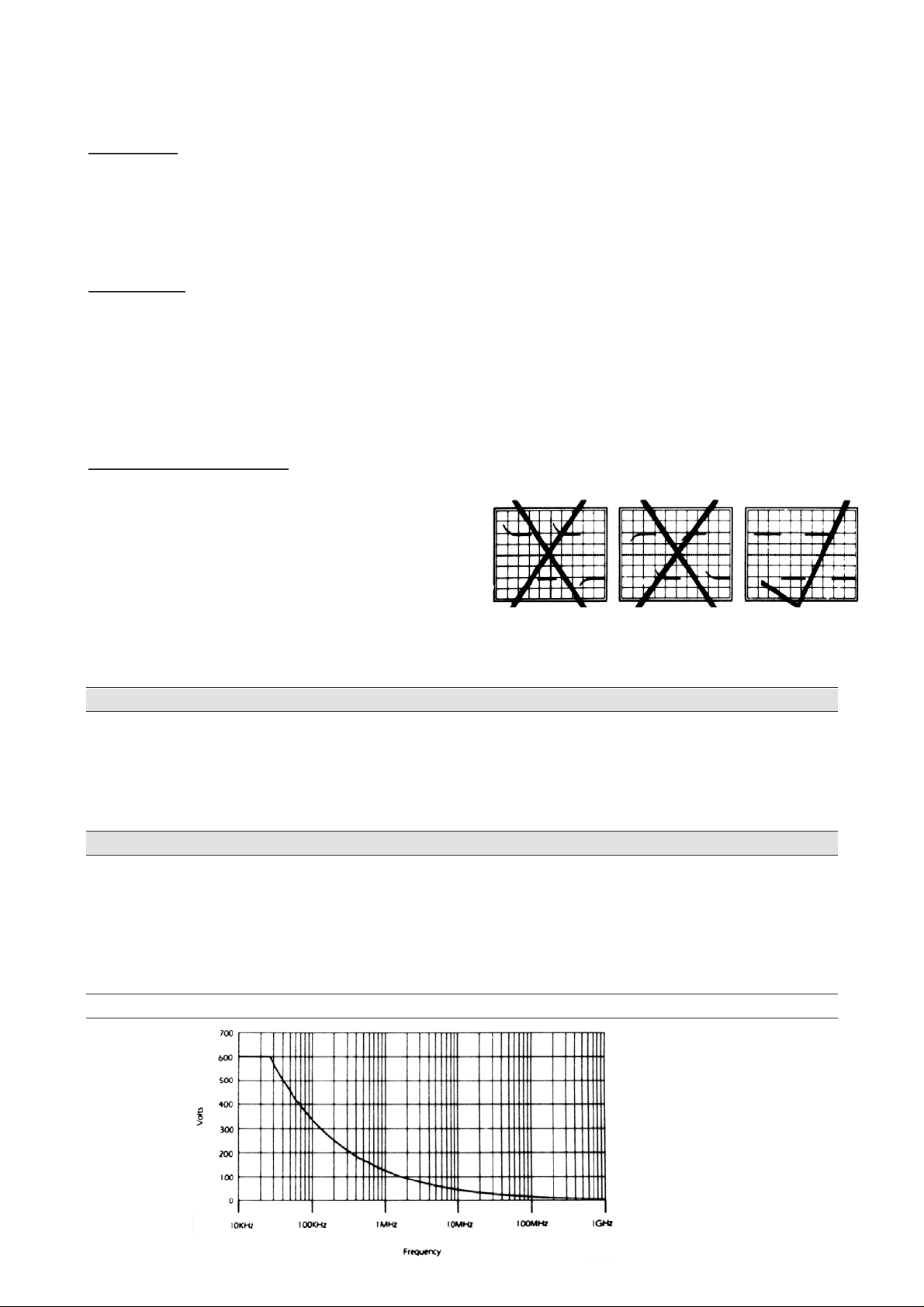
Working Voltage 600 V DC incl. Peak AC derating with f requency
Position x10
Attenuation Ratio 1:10
Bandwidth DC tot 60 MHz
Rise Time 5.5 ns
Input Resistance 10 Mohm when used with oscilloscopes with 1Mohm input
Input Capacitance Approx. 18pF
Compensation Range 10 to 35 pF
Working voltage 600 V DC incl. peak-AC derating with frequency (see Fig. 1)
Cable length ±140 cm
Page 3

NEDERLANDS
Oscilloscope Probe Kit
Inleiding
De PROBE60S is een passieve probe m et hog e impedant ie, ont worpen en geijk t voor gebr uik met
apparaten met een ingangsimpedantie van 1 Mohm en een parallelcapaciteit van 25 pF.
Compensatie is mogelijk voor ing angscapaciteiten tussen 10 en 35 pF. In de kop van de probe
bevindt zich een schakelaar om de verzwakkingsfactor in t e st ellen ( x1 of x10).
Onderhoud
Controleer of de probe niet meer verbonden is met een spanningsbron alvorens ze te
ontmantelen.
De probekop kan gescheiden worden van de kabel door beide delen van de BNC-connector uit
elkaar te trekken. Dit laat toe de probekop of de kabel afzonderlijk te vervangen bij eventuele
beschadiging. Ook de meet -tip is vervangbaar. Met een tangetje kan het zwarte isolerende deel
van de tip vastgenomen worden en voorzichtig uitgetrokken worden. Zorg voor een goed
elektrisch contact met de pr obekop bij het aanbrengen van de nieuwe tip.
Compensatieregeling
Om correcte meetwaarden te verkr ijgen dient het
verzwakkingsnetwerk te worden gecalibreerd. Dit
kan gebeuren met behulp van een 1 KHz
blokgolf, eventueel afkomstig van de
calibreringsuitgang van de scoop.
Regel de trimmer in de BNC connector met een kunststof schroevendraaier zodanig dat de
hoeken van de blokgolf zo weinig mog e lij k afronding vertonen.
Specificaties
Positie x1
Verzwakking 1:1
Bandbreedte DC tot 15 MHz
Stijgtijd 27 ns
Ingangsweerstand 1Mohm (ingang oscilloscoop)
Ingangscapaciteit 46 pF + cap. oscilloscoop
Werkspanning 600 V DC incl. piek-AC vermindert bij stijgende freq.
Positie x10
Verzwakking 1:10
Bandbreedte DC tot 60 MHz
Stijgtijd 5.5 ns
Ingangsweerstand 10 Mohm (indien ingang scoop = 1 Mohm)
Ingangscapaciteit ±18 pF
Compensatiebereik 10 tot 35 pF
Werkspanning 600 V DC incl. piek-AC vermindert bij stijgende freq.
Lengte kabel ±140 cm
Page 4

FRANÇAIS
Kit Oscilloscope Sonde
Introduction
La PROBE60S est une sonde passive de haute impédance, construite et réglée pour un usage
avec des appareils ayant une impédance d’entrée de 1 Mohm et une capacité parallèle de 25 pF.
Une compensation est possible pour des capacités d’ent rée entre 10 et 35 pF. Dans la tête de la
sonde se trouve un interrupteur permett ant de choisir l’atténuation (x1 ou x10).
Entretien
Débranchez la sonde avant de la démonter.
La tête de la sonde peut êt re séparée du câble en t irant les deux parties du connecteur BNC. Ceci
permet de remplacer le câble ou la tête en cas d’endommag ement. La pointe de la sonde est elle
aussi remplaçable. Avec une pince on peut séparer la partie noire (isolante) de la point e. Vérifiez
que il y a un bon contact entre la pointe et la tête.
Réglage de compensation
Pour obtenir des mesures correctes, il est
nécessaire de calibrer le réseau d’atténuation.
Ceci est fait avec des impulsions (1 KHz), qui
viennent éventuellement de la sortie de calibrage
de l’oscilloscope.
Réglez le condensateur ajustable dans le connecteur BNC avec un tournevis en plastic jusqu’à
l’obtention d’un sommet le plus plat possible de la tension.
Données Techniques
Position x1
Atténuation 1:1
Bande passante DC à 15 MHz
Temps de montée 27 ns
Résistance d'entrée 1 Mohm (entrée oscilloscope)
Capacité d'entrée 46 pF + cap. Oscilloscope
Tension max 600 V CC incl. CA max. (réduit avec fréq. ascendante)
Position x10
Atténuation 1:10
Bande passante DC à 60 MHz
Temps de montée 5.5 ns
Résistance d'entrée 10 Mohm (si rés. d'entrée oscilloscope = 1 Mohm)
Capacité d'entrée +/- 18pF
Réglage de compensation 10 to 35 pF
Tension max 600 V CC incl. CA max. (réduit avec fréq. ascendante) (voir Fig. 1)
Câble ±140 cm
 Loading...