

Page 1

12
+
SOLDERLESS
EDUCATIVE STARTERBOX
Demo's on
Page 2

VELLEMAN NV
Legen Heirweg 33
9890 Gavere
Belgium Eur o pe
www.velleman.be
www.velleman-kit.com
Page 3

11 exciting projects which you can actually use.
Projects featured in this box:
LED with push button* ................................................................. Light a LED when a pushbutton is pressed (pag.10)
A transistor as cuurent amplifier
As t ab l e mu ltivi b rato r
** ......................................................................................... Let LEDs flash alternately (pag.14)
Simple bur glar alarm w ith LE D indication and so u nd
Ligh t detector
Polarity tester
Start-Stop circuit
Timer circuit
Ligh t switch
Water alarm
**......................................................................... Switch on a LED when there is sufficient light (pag.18)
* ............................................................................................................Check battery polarity (pag.20)
*** ................................................................................. Control a LED using 2 pushbuttons (pag.22)
*** ............................................................................... Make a LED switch off after a certain time (pag.24)
*** .......................................................................... Make a LED switch on when it becomes dark (pag.26)
** .......................................................................................... Make a liquid level trigger an alarm (pag.28)
Running lig ht with 3 LEDs
Difficulty level
* easy
** normal
*** hard
* .................................................................. Light a LED using a transistor (pag.12)
** .......................... Example of a simple burglar alarm (pag.16)
*** ...................................................... Make 3 LEDs light up shortly in succession (pag.30)
: see "velleman EDU01"
www.vellemanprojects.com
Pag. 3
Page 4
Parts supplied with this kit:
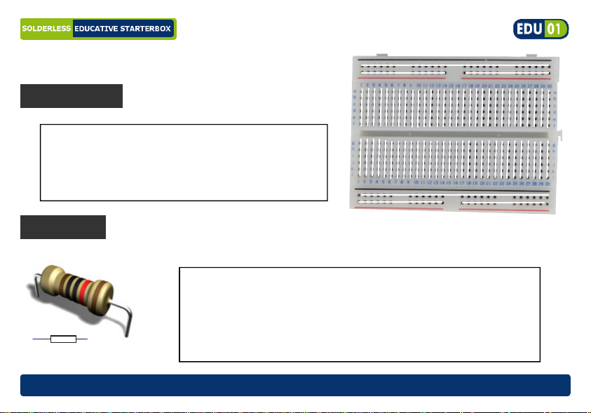
Breadboard
The breadboard will hold all your
experiments. The white lines show how the
holes are electrically connected wit h
eachother
Resistors
R1
100
(Velleman part# SDAD102)
Various resistor values are supplied. They serve as
current limi ters or as voltage div iders. Resistors do not
have a polarity. Resistors values are indicated by
means of coloured rings. The unit of resistance is called
’Ohm’. ( see colour code table in the package)
pag. 4
www.vellemanprojects.com
Page 5
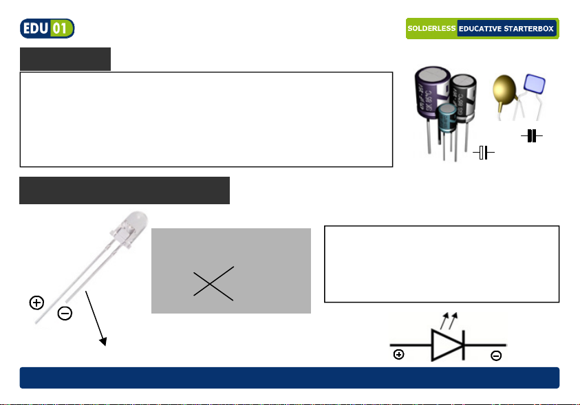
Capacitors
A capacitor is almost lik e a small battery, it can be charged
using a power supply. Mostly used to stabilise or to filt er out
unwanted voltages. The unit is Farad: practi c al v alues are
in µF, nF or pF. The supplied capacitor is an Electrolytic
capacitor of 10µF and has a polarity, the long lead = +
(Velleman part# 10J0E)
Green & red LED
How to bend the leads:
A LED is a Light Emitting Diode, it
can emit light using a small current
(max 20mA with a 1.8V drop).
Watch the polarity, long lead = + !
(Velleman part# L-7104LGD & L-7104LID)
Flat side, shortest lead = (-)
NG
OK
C...
C...
www.vellemanprojects.com
Pag. 5
Page 6
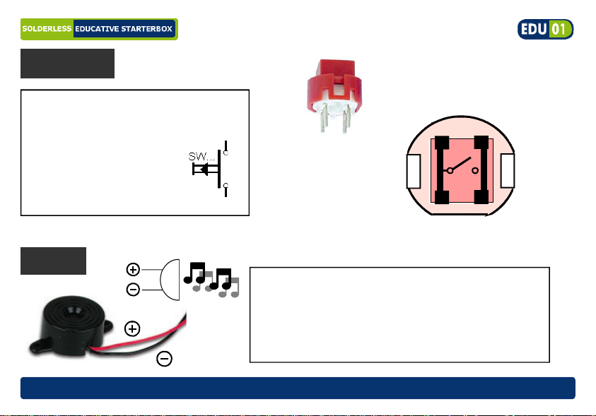
Push button
A push button will conduc t current
when pushed and interr upt the
current when released.
(Velleman part# D6)
Buzzer
pag. 6
Inside connection
The supplied button
has 4 connections, but
only 2 are used.
2 are interconnected.
A buzzer produce a signalling sound to alert
for a dangerous situation, timer confi rmation,
a button is pressed, .. . T he pitch of the buzzer
can't be changed because the frequency of
the oscillat or is fixed.
(Velleman part# SV3)
www.vellemanprojects.com
Page 7
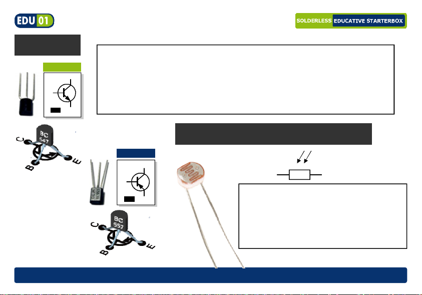
Transistors
C B E
BC547
B
NPN
A transistor is an amplification device. By means of a small
current, a muc h larger current is contr olled. Transistors come i n
C
two flavours, NPN and PNP-types, depending on the polarity.
With this kit, you receive a BC557 (PNP) and a BC547 (NPN)
transistor. A tr ansistor has 3 pins: Base, Emitt er and Collector.
E
(Velleman part# BC557B, BC547B)
LDR (Light Dependent Resistor)
E B C
www.vellemanprojects.com
BC557
B
PNP
C
E
A Light Dependent Resistor behaves
like a resistor. T he resistance v arious
on the amount of light falling on the
device, it decreases with increasing
light intensity.
Velleman part# LDR04)
Pag. 7
Page 8
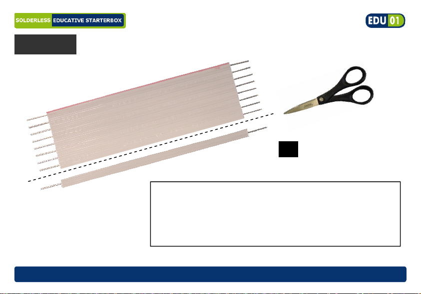
Flatcable
8x
Includi ng in this box you can find a mult i-cor e cable. The
wires must be separated from each other before use.
This can be done using a wire-c utter or pair of scissors.
Use the separate wir es to c onnec t component s (indicated
in the drawing by a thick black line)
Vell e ma n pa r t # FC 8)
pag. 8
www.vellemanprojects.com
Page 9

PROJECTS
PROJECTS
PROJECTS
www.vellemanprojects.com
Pag. 9
Page 10
*
*Not included
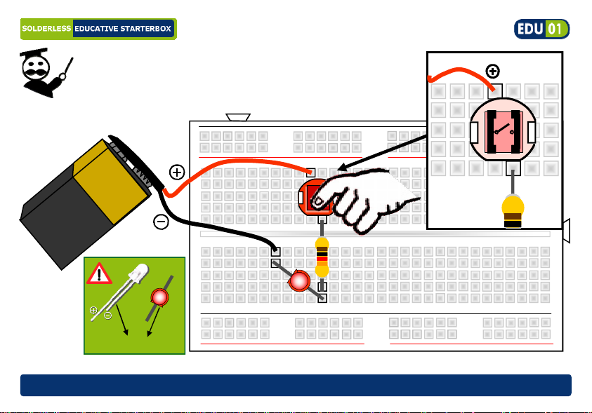
Project 1: LED with push button
Project 1: LED with push button
As long as the push button is pressed the led will light
RED
V
9
1K
Flat side, shortest leg = (-)
pag. 10
www.vellemanprojects.com
Page 11

Required parts: 9V battery*, 1000 ohm resistor (brown black red ), red LED,
push-button
How it works: As long as the push button is
pressed, a closed ci rcuit is formed that makes the
current flow and the LED lights up.
Current flows from the (+) of the battery to the
push-button, r esistor, (+) of the LED and via the (-)
of the LED back to the battery .
Using a 1000ohm resistor the cur rent will be about
0.007A (7mA).
Calculation of the resistor:
resistor = battery voltage – LED voltage
resistor = 9V - 1,8V = 1000ohm
0,007
LED current
Time to experiment :
What happens when you swap (+) and (-) of the led?
What happens when you replace the 1000 ohm resistor
with a 100K ohm resistor (brown black yellow gold) ?
www.vellemanprojects.com
Pag. 11
Page 12

Project 2:
Project 2:
Transistor acting as current amplifier
Transistor acting as current amplifier
*
*Not included
pag. 12
Light up a LED using a transi stor , use your finger as a switch
Jumper wire
1K
V
9
1K
K
7
4
C
B
E
www.vellemanprojects.com
Page 13

Required parts: 9V battery*, 1K resistor (brown black red gol d) , 470K resistor (yell ow
purple yellow gold), red LED, BC547 transistor, wire jumper.
How it work s : In this circuit, the small
current flowing through your finger will be
amplifi ed by the transistor.
The base current that runs via your finger
and resistor R1, i s amplif ied by transistor T1.
The amplified curr ent flows through the LED
and R2 making the LED lit.
R3 will prevent the t r ansi stor for unwanted
functioning.
HINT: wet you finger to make the LED
light up stronger.
www.vellemanprojects.com
Pag. 13
Page 14

Project 3:
Project 3:
**
Let LEDs flash alt ernately
Astable multivibrator (flashing LEDs )
Astable multivibrator (flashing LEDs )
9
*Not included
pag. 14
V
WATCH THE
CAPACITOR
POLARITY
1K
100K
C1
C2
C
B
E
100K
1K
C
B
E
www.vellemanprojects.com
Page 15

Required parts: 9V battery*, 2x 1K resistor (brown black red gold), 2x 100K resistor
(brown black yell ow gold) , 2x red LED, 2 x BC547 transistors, 2x 10µF elec trolytic
capacitors
How it work s : The 2 transistors
alternately c onduc t bec ause the
capacitors are c har ged and discharged.
The speed at which thi s happens
depends on the capacitors (C1, C2)
and the resistors (R1, R2). Use a
higher capacitor and resistor value in
order to extend the LED light ing time.
The LED on-time can be calculated:
T = 0,693 x R1(Ω) x C1 (F)
T = 0,693 x 100.000 x 0.00001 = 0,693sec.
www.vellemanprojects.com
Pag. 15
Page 16

Project 4:
Project 4:
**
Make an alarm signal sound when the ci r c uit is interrupted...
Simpl e burglar al arm with LED indi cation an d sound..
Sim ple bu rgl ar al ar m wi th LED in di cat ion an d sou nd
100K
*Not included
pag. 16
9
V
1K
C
B
E
0,5m supplied wire
www.vellemanprojects.com
Page 17

Required parts: 9V battery*, 1K resistor (brown black red gol d) , 100K resistor (brown
black yellow gold), red LED, BC547 transistor, buzz er , 0,5m supplied wire.
How it work s : An alarm sounds when the
normally closed securi ty circuit (here
indicated as ‘WI RE ’) is i nterr upted.
Replace this normally closed circuit
(WIRE) by a normally closed window or
door switch; when e.g. the window is
opened the contact within the window
switch is interrupted, the security circuit is
opened and the buzzer sounds.
The alarm signal ends as soon as the
security cir c uit is closed again.
www.vellemanprojects.com
Pag. 17
Page 18

Project 5:
Project 5:
**
Switch on a LED when there i s suffici ent light
Light d e t ector
Light d e t ector
*Not included
pag. 18
9
V
10K
10K
B
E
1K
C
www.vellemanprojects.com
Page 19

Required parts: 9V battery*, 1K resistor (brown black red gol d) , 2x 10K resistor
(brown black orange gol d) , red LED, BC547 transistor, LDR.
How it works: A LED lights up when enough
light hits the LDR. The LDR is a light sensitiv e
resistor (Light Dependent Resistor), in dark
conditions it has a high resistance, and in li ght
conditions it s resi stanc e bec omes low.
Across the LDR is a posit ive potential which is
fed to the base of the transistor enabling it to
switch. Resistor R2 creates a switching point
which determines when the transistor starts to
conduct. Resistor R1 limits the current that
flows through the LDR.
www.vellemanprojects.com
Pag. 19
Page 20

Project 6:
Project 6:
*
Check the polarity of a bat tery
polarity t es ter .
polarity t es ter .
GREEN RED
*Not included
pag. 20
9
V
1K
Jumper wire
www.vellemanprojects.com
Page 21

Required parts: 9V battery*, 1K resistor (brown black red gol d) , red LED, green LED,
wire jumper
How it works: When the 9V battery is
connected to the ci rcuit wi th the right
polarity the green LED (good) will light
up. Current can f low from the "+" of the
battery through the green LED and via
the resistor back t o the "–" of the batt ery.
The red LED (wrong) wil l not light up as it
GREEN RED
is polarised in the opposite direction.
When swapping the connection of the
battery (switch the red and the black
wires) the red LED will light up. This way
we can determine whether a battery is
connected the right way or not.
www.vellemanprojects.com
Pag. 21
Page 22

***
Project 7: S tart--
Project 7: S tart
stop circuit.
stop circuit.
Control a LED using 2 pushbuttons
T2
E
B
C
10K
1K
pag. 22
9
V
*Not included
1K
SW2 SW1
Jumper wire
1K
C
T1
B
E
Jumper wire
Jumper wire
www.vellemanprojects.com
Page 23

Required parts: 9V battery*, 3 x1K resistor (brown black red gold), 10K resistor
(brown black orange gol d) , red LED, 2 x push-button, 1x BC547 transi st or , 1x BC557
transistor, 5 x wir e jum per
How it works: The “START” butt on will
light up the LED; it will remain on when
the pushbutton is released. To switch off
the LED, press the “STOP” button.
T1 and T2 ar e in stat e of rest (OF F, no
current). By pressing the “START ” button a current flows via R4 through the
LED. At the same time the base of T2 is
pulled l ow (was high v ia R1). Since t he
value of R3 i s much lower than R1 t he
voltage on the base of T 2 drops m aking
it conduct and via the collector of T2 and
R2. T1 also start s to conduct. From this point on, both transistors ke ep each other in conducting state, even when the “STA RT” button i s released. Pressi ng the “STOP” butt on will
end the current fl ow towards the ba se of T1 and it will stop conducting. The circuit is interrupted and T2 will also stop conducting. The LED will turn off.
www.vellemanprojects.com
Pag. 23
Page 24

***
Project 8: Tim er circuit.
Project 8: Tim er circuit.
Make a LED switch off after a certain time
*Not included
pag. 24
9
V
C
E
1K
Jumper wire
B
C
B
10µF
E
Jumper wire
100K
Jumper wire
www.vellemanprojects.com
10M
Page 25

Required parts: 9V battery*, 1K resistor (brown black red gol d) , 100K resistor (brown
black orange gol d), 1M resi stor ( br own bl ac k gr een gold) , Red LED, push-button, 2x
BC547 transistor, 10µF electrolyti c capacitor, 3 x wire jumper
How it work s : When pushing the push
button shortly , the LED will turn on and aft er
a while it will go out. By pushing the push
button the capaci t or will quickly charge; when
releasing the button the capacitor will release
its stored energy via both transistors – both
will start to conduct and the LED will light up.
The current needed to make T2 conduct is
R1
10M
limited as T1 a nd T2 form a Darlington transistor circuit. The time needed to discharge
the capacitor is also determined by resistor
R1. The smaller R1 the f aster the c apacitor is
discharged and the LED switches off. When
R1 is removed, the capacitor discharges
solely via the base current of T1. Switching
off is a lot slower now and takes ± 1 minut e.
The total gain of both transistors can be calculated: ß = ß(T1) x ß(T2)
In electronics, the Darlington circuit is a
structure consisting of two bipolar
transistors connected in such a way
that the current amplified by the first
transistor is amplified further by the
second one. This configuration gives a
much higher current gain than each
transistor taken separately.
www.vellemanprojects.com
Pag. 25
Page 26

***
Project 9: Li ght swit ch
Project 9: Li ght swit ch
Make a LED switch on when it becom es dark
*Not included
pag. 26
9
V
10K
10µF
C
100K
Jumper wire
1k
1k
E
B
10K
www.vellemanprojects.com
E
C
B
100
Page 27

Required parts: 9V battery*, 100 ohm res istor (brow n black brown gold), 2 x 1K resis tor
(brown black red g old), 2 x 10K r es istor (br ow n black orange gold), 100K resistor ( brow n
black yellow go ld), 2 x BC547 transistor, 10µF e lectro lyte ca pac itor, LDR , Red LED , 2 x w ire
jumper
How it works: This circuit will make a
LED switch on when i t becomes darker.
Transistors T1 and T2 form a Schmitttrigger circuit. The output of a Schmitt
trigger is swit ched over at a certain voltage at the input (the trigger level). The
purpose here is the switch t he LED on or
off completely . As long as there is no l ight
on the LDR there is no base current to T1
R6
100K
and it will not conduc t. As long as this is
the case, T2 will receive a base current
via R2 and R3 and conducts; the LED will be on. When li ght shines on the LDR the
voltage on the base of T 1 ri ses. T1 will start to conduct when this volt age is hi gher than
the voltage ov er R5 + U
of T1. When this is the case, the base voltage of T2 drops and
be
T2 does not longer conduct and the LED goes off. Because of the change in flow
through R5 when the LED switches off , the threshold level for which T2 will conduct
again in darkness also changes.
www.vellemanprojects.com
Pag. 27
Page 28

**
*Not included
Project 10 : Water alar m
Project 10 : Water alar m
Make a liquid level tri gger an alarm
10K
V
9
Do not use a
flammable
substance
470K
wire
MAX
B
E C
B
C
E
pag. 28
www.vellemanprojects.com
Page 29

Required parts: 9V battery, 10K resistor (brown black orange gol d) , 470K resistor
(yellow purple yellow gold), buzzer, 2x BC547 t r ansi stor , 2 wires
How it works: The 2 sensor wires
must be placed in a t ank at a certain
distance (e.g. use a drink ing cup). F ill
up the tank with a conducting liquid
(e.g. water) until the level reaches
both sensor wires. A small current
will flow via R2 towards the base of
T2. The base is protected against
interfer ence with a resistor R1.
T1 & T2 are configured as a Darlington switch hence onl y a v er y sm all c ur r ent is needed
to make T1 conduct and activ ate the alarm sound.
www.vellemanprojects.com
Pag. 29
Page 30

***
Project 11 :
Project 11 :
Running light with 3 LEDs
Running light with 3 LEDs
Make 3 LEDs without cont r ol light up successively
Jumper wire
9
*Not included
pag. 30
V
1K
100K
1K
100K
1K
100K
Jumper wire
C C C
B
E
E E
B B
www.vellemanprojects.com
Page 31

Required parts: 9V battery*, 3x1K resistor (brown blac k r ed gold), 3x100K resistor
(brown black yell ow gold) , 3 x red LED, 3x BC547 transistor, 3x10µF electrolytic capaci tor, 2x wire jumper
This cir c uit makes each LED light up short ly in succession. The c ircuit consists of 3 identical
channels. It i s theoreti cally possible to ex pand; per LED a simi lar cir cuit is needed in serie s
with the prev ious. The capacit or of the next channel is charged when the tr ansistor of the
previous channel is not conducting. As long as a certain transistor is not conducting, the relevant LED will li ght up. Capaci tor C4 is added to t he ci rcui t to cr eate a cer tai n start i ng condi tion when connecting power and to ensure a good operation.
Time to experiment: What happens when you change the value of R1, R2 and R3 to 10K?
www.vellemanprojects.com
Pag. 31
Page 32

02
04
The Mic rochi p na me and l ogo, PIC, an d PICmicr o are re gistere d trade marks of Mi croch ip Technol ogy Inc. in
the USA an d other countri es.
SOLAR ENER GY
Fun solar powered projects . Learn all about solar
energy.
PICTM
TUTOR KIT
Enter the world of microcontroller
programming, easy step by step instructions.
Includes programmer and test board.
EXPERIMEN T KIT
03
05
SOLDER EDUC ATIVE
Learn how to solder, build different exciting projects.
Includes spare components and
demo boards.
USB
TUTOR BOARD
Learn how to connect your computer
with the outside world, master the
USB communication with tutorial examp les.
Play with LED indicators and learn how to drive
LCDisplays.
STARTER BOX
06
Modifications and typographical errors reserved. © Velleman nv, Legen Heirweg 33 - 9890 Gavere (België)
HEDU01 - 2011- ED1
EDUKIT SCOPE
This board with different signals will
teach you how to use an oscillos cope.
Optimized instructions for use of our HPS140
oscilloscope. YouTube demo movies .
5 410329 438111
 Loading...