

Page 1
DDPH2
DRYWALL AND PANEL HOIST
LÈVE-PLAQUE
PLATENLIFT
ELEVADOR DE PLACAS
PLATTENLIFT
ELEVADOR DE PLACAS
USER MANUAL 3
NOTICE D’EMPLOI 7
GEBRUIKERSHANDLEIDING 11
MANUAL DEL USUARIO 15
BEDIENUNGSANLEITUNG 19
MANUAL DO UTILIZADOR 23
Page 2

DDPH2
00 (11/12/2012)
2
Page 3

DDPH2
User manual
1. Introduction
The DDPH2 drywall and panel hoist enables drywall panel lifting by a single person.
Thank you for choosing Perel! Please read the manual thoroughly before bringing this device into
service. If the device was damaged in transit, do not install or use it and contact your dealer. Damage
caused by disregard of certain guidelines in this manual is not covered by the warranty and the
dealer will not accept responsibility for any ensuing defects or problems.
2. Safety Instructions
Keep the device away from children and unauthorised
users.
Indoor use only.
Keep the device away from rain, moisture, splashing and
dripping liquids.
Always wear a (hard) safety helmet when operating
the panel hoist.
Always wear protective gloves when operating the
panel hoist.
Always wear protective glasses when operating the
panel hoist.
Damage caused by disregard of certain guidelines in this manual is not covered by the warranty and
the dealer will not accept responsibility for any ensuing defects or problems.
Note that damage cause d b y us er mo di fi cati o ns to the device is not covered by the warranty.
3. General Guidelines
Protect this device from shocks and abuse. Avoid brute force when operating the device.
Protected the device against extreme heat, dust and moisture.
Familiarise yourself with the functions of the device before actually using it.
All modifications of the device are forbidden for safety reasons.
Only use the device for its intended purpose. Using the device in an unauthorised way will void the
warranty.
Always inspect the device before use. Pay special attention to the steel cable.
Allow the device to stabilize to working room temperature before use. Condensation could affect the
proper operation of the winch brake. Always make sure the brake drum is dry and clean.
Do not use the lift when locking springs are not in place.
Watch for overhead obstructions when operating the lift. Keep the working area free of obstructions.
DO NOT use the lift for any other purpose than lifting drywall panels. Do not lift more than
one panel at a time and do not lift more than 68kg.
4. Features
Suitable to hoist dry panels
For panels up to 4.88m x 1.22m
Can be used for mounting level and sloped ceilings or walls
Cradle lowers for easy loading
Breaks down in 3 parts for easy moving
No tools required for assembly/disassembly
00 (11/12/2012)
3
Page 4

DDPH2
5. Overview
Refer to the drawing on page 2 of this manual.
# Description # Description
1 Centre leg 14 Pulley
2 Outer leg 15 Retaining hook
3 Caster (with brake) 16 Winch wheel
4 Sliding yoke 17 Winding drum and brake assembly
5 Positioning arm 18 Brake lever with spring
6 Backstop 19 Winch wheel handle
7 Main vertical frame 20 Load cradle
8 Telescopic section – inner part 21 Extendable arm with protective caps
9 Telescopic section – outer part 22 Extendable arm pin lock
10 Winch assembly 23 Cradle mounting head with tilt latch
11 Slide bar 24 Crossbar with protective caps
12 Slide bar lock 25 Hook for panel support
13 Steel cable
6. Assembly
The drywall lift is composed of 3 main parts:
o Tripod base assembly
o Vertical frame assembly
o Cradle assembly
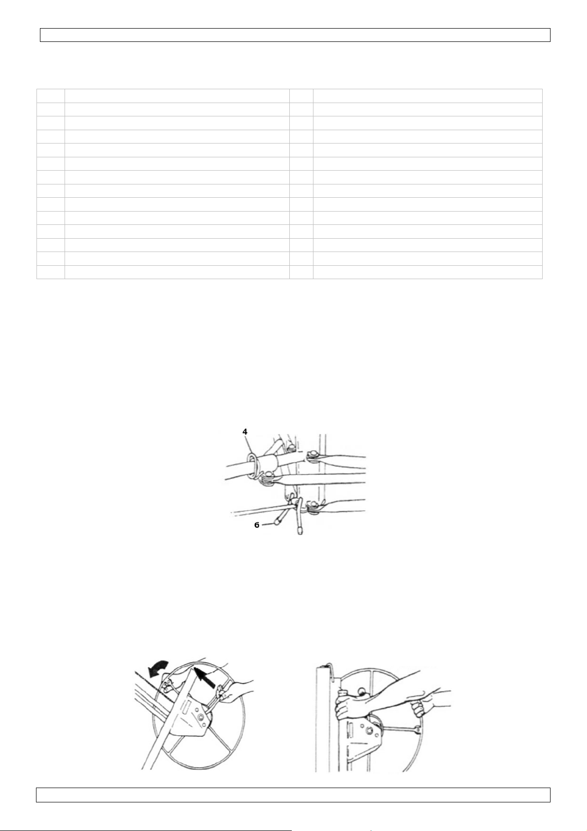
Tripod base
Mount the casters [3] in the tripod base.
Place the base on its casters [3] and lower the backstop [6].
Press and hold the ring of the yoke [4] down while unfolding the two outer legs [2], until the
yoke pin snaps into the locking hole near th e centre of the tripod.
Figure 1
Vertical frame
Install the vertical frame [7] in the V-shaped angles on the tripod base. Make sure the frame is
pushed all the way down.
Attach the handle [19] to the winch wheel [16].
Move the winch assembly [10] into working position by holding the wheel [16] and brake
handle [18] as shown in figure 2. Push the brake handle all the way up while rotating the wheel
slightly forward, grab the winch arm and secure the brake handle with your thumb to prevent
backlash (figure 3).
Figure 2 Figure 3
00 (11/12/2012)
4
Page 5

DDPH2
Make sure the retaining hook [15] on top of the frame is preventing the telescopic sections
[8][9] to move. Put your right hand on top of the vertical frame [7] and pull the assembly [10]
towards you while holding the brake lever.
Rotate the lock [12] at the end of the slide bar [11] as far as possible clockwise when the winch
assembly is fully extended to secure the winch assembly position. Always check whether the
lock is engaged before lifting a load.
Pull the retaining hook [15] away to allow the telescopic sections [8][9] to move freely.
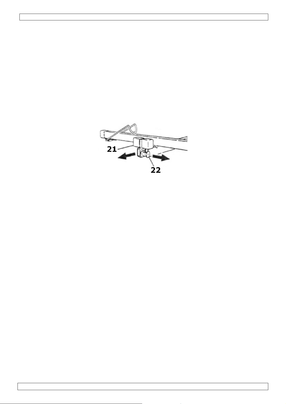
Cradle assembly
Attach the load cradle [20] on top of the vertical frame [7] by inserting the pin of the cradle
head [23] into the hole of the inner telescopic section [8]. Make sure that the tilt latch is
hooked over the protrusion to avoid accidental tilting of the cradle.
Attach the crossbars [24] to the cradle [20] by sliding the tapered plates of the crossbars into
the tapered sockets of the cradle until the flat spring on the bottom of the crossbar snaps in
place. The two crossbars are identical.
Slide the extendable arms [21] in the cradle, with the holes facing the pin locks [22] (see figure
4).
Figure 4
7. Operation
First verify that the lift is not damaged (especially the cable) and that the brake drum [17] is
clean and dry. Make sure the lift is at room temperature.
Lock the casters [3] of the lift and lower the backstop [6].
Lower the cradle [20] by turning the winch wheel [16].
Release the tilt latch and tilt the cradle [20].
Position the hooks [25] to support the panel. Turn the cradle so the hooks are facing away from
the winch wheel [16].
Extend the arms [21] as far as necessary to support the whole panel. The arms can be extended
in 3 positions. For safety reasons, the pin of the pin lock must always be secured in one of the
holes of the extendable arm. Do not use the lift when the pin locks are not secured.
Place a panel on the hooks [25], finish side facing the crossbars [24]. Gently lower the panel
onto the crossbars and extension arms.
For ceiling mounting, tilt the cradle horizontally and hook the tilt latch over the protrusion to
secure it. Note that there is still about 10° side-to-side slack. For sloped panel mounting, leave
the cradle unlatched.
Unlock the casters [3] and raise the backstop [6]. Carefully roll the lift to where the panel needs
to be installed.
For sloped or wall panel mounting, always lower the backstop [6] before lifting the panel.
Turn the winch wheel [16] until the panel is at the desired height. Always check for overhead
obstructions when lifting a panel. Note that the brake is spring-operated, preventing the panel
from automatically lowering when releasing the winch wheel.
To lower the panel, hold the winch wheel [16] and slowly release the brake handle [18].
Make sure the panel is sufficiently attached to the wall or ceiling before removing the
hoist.
00 (11/12/2012)
5
Page 6

DDPH2
8. Disassembly
To disassemble the lift, lower the cradle [20] as far as possible, and slide the extension arms all
the way in.
Remove the crossbars [21] by pushing on the flat springs and separating the tapered plates.
Unlock the tilt latch and lift the cradle about 8cm to release it from the vertical frame.
Hook the retaining hook [15] over the telescopic parts [8][9].
Rotate the lock [12] at the end of the slide bar [11] counter clockwise and lift the slide bar
[11].
Turn the winch wheel [16] until the winch assembly [10] is tight to the vertical frame [7].
Gently pull the vertical frame [7] up while holding the tripod down.
Press and hold the ring of the yoke [4] down while folding the two outer legs [2], until the yoke
pin snaps into the locking hole near the caster.
9. Maintenance/storage
Keep the brake drum [17] clean and dry at all times. Check the drag on a regular basis to
ensure proper functioning of the hoist.
Occasionally oil the cable pulleys. To access the inner pulleys, winch the lift up as far as possible.
Occasionally oil the bearings of the casters.
When operation becomes less smooth, apply some household paraffin to the sliding surfaces.
Always store the hoist in a clean and dry area protected from harsh conditions.
10. Technical specifications
lift
height
load weight (max.) 68kg (150lbs)
load dimensions (max.) 4.88 x 1.22m (16 x 4 ft)
Weight ± 48kg
Use this device with original accessories only. Velleman nv cannot be held responsible in
the event of damage or injury resulted from (incorrect) use of this device.
For more info concerning this product, please visit our website www.perel.be.
The information in this manual is subject to change without prior notice.
max. 3.35m (11 ft)
min. 1.22m (4 ft)
loading 0.86m (34 in )
00 (11/12/2012)
6
Page 7

DDPH2
NOTICE D’EMPLOI
1. Introduction
Le lève-plaque DDPH2 est un appareil de levage pour plaques de plâtre maniable par une seule
personne.
Nous vous remercions de votre achat ! Lire la présente notice attentivement avant la mise en
service de l’appareil. Si l’appareil a été endommagé pendant le transport, ne pas l’installer et
consulter votre revendeur
2. Prescriptions de sécurité
Garder le lève-plaque hors de la portée de personnes non
qualifiées et de jeunes enfants.
Pour usage à l’intérieur uniquement.
Protéger le lève-plaque contre la pluie, l’humidité et les
éclaboussures.
Utiliser un casque de sécurité lors de l’utilisation de
ce matériel.
Utiliser des gants de sécurité lors de l’utilisation de
ce matériel.
Utiliser des lunettes de sécurité lors de l’utilisation de
ce matériel.
La garantie ne s’applique pas aux dommages survenus en négligeant certaines directives de cette
notice et votre revendeur déclinera toute responsabilité pour les problèmes et les défauts qui en
résultent.
Les dommages occasionnés par des modifications à l’appareil par le client ne tombent pas sous la
garantie.
3. Directives générales
Protéger le lève-plaque contre les chocs et le traiter avec circonspection pendant l’inst allation et
l’opération.
Tenir le lève-plaque à l’écart de la poussière, l’humidité et des températures extrêmes.
Se familiariser avec le fonctionnement de l’appareil avant de l’utiliser.
Toute modification de l’appareil est interdite pour des raisons de sécurité.
N’utiliser le lève-plaque qu’à sa fonction prévue. Un usage impropre annule d'office la garantie.
Inspecter le lève-plaque et le câble en acier avant chaque utilisation.
Afin d’éviter des dommages, attendre jusqu’à ce que l’appareil ait atteint la température ambiante
avant de l’utiliser. S’assurer que le tambour soit propre et sec.
Ne pas utiliser le lève-plaque tant que les goupilles à ressort de verrouillage ne soient pas en place.
Libérer l’environnement du lève-plaque de tout obstacle afin d’éviter tout danger potentiel.
Ce lève-plaque est destiné exclusivement à la pose de plaques de plâtre. Ne pas soulever
plus d’une plaque à la fois ou une charge d’un poids supérieur à 68 kg.
4. Caractéristiques
matériel de levage pour plaques de plâtre
convient pour des plaques jusqu'à 4,88 m x 1,22 m
pour plafonds et rampants
antenne articulée pour faciliter le chargement
démontable en 3 pièces - peut facilement être transporté
assemblage et démontage sans outils
00 (11/12/2012)
7
Page 8

DDPH2
5. Description
Consulter l’illustration à la page 2 de cette notice.
# Description # Description
1 pied central 14 poulie
2 pied extérieur 15 crochet de rétention
3 roulette (avec frein) 16 treuil
4 joug coulissant 17 ensemble tambour-frein
5 stabilisateur 18 manette de frein à ressort
6 crochet de pied 19 levier du treuil
7 mât principal 20 poutre centrale
8 mât télescopique – partie intérieure 21 rallonge avec protection
9 mât télescopique – partie extérieure 22 goupille à ressort de la rallonge
10 ensemble treuil 23 tête de mât avec tirette d’indexeur
11 coulisse 24 té latéral avec protections
12 verrouillage de la coulisse 25 butée de plaque
13 câble en acier
6. Assemblage
Le lève-plaque est composé de 3 parties :
o ensemble piètement
o ensemble mât
o antenne de chargement
Ensemble piètement
Monter les roulettes [3] sur les pieds.
Placer le piètement sur les roulettes [3] et positionner les crochets de pied [6].
Enfoncer en maintenir l’anneau du joug coulissant [4] tout en ouvrant les deux pieds extérieurs
[2] jusqu’à ce que la goupille du joug coulissant se bloque dans le trou.
Illustration 1
Ensemble mât
Glisser le mât principal [7] dans la réservation en V du piètement. S’assurer que le mât soit bien
enfoncé dans la réservation.
Fixer le levier [19] au treuil [16].
Placer l’ensemble treuil [10] en position de service en tenant le treuil [16] et la manette de
frein [18] comme illustré (ill. 2). Pousser le frein en tournant légèrement le treuil v ers l’avant,
saisir le bras du treuil et bloquer le frein avec le pouce afin de retenir l’ ensemble (ill. 3).
Illustration 2 Illustration 3
00 (11/12/2012)
8
Page 9

DDPH2
Veiller à ce que le crochet de rétention [15] bloque les mâts télescopiques [8][9]. Placer la
main droite en haut du mât [7] et tirer l’ensemble treuil [10] vers vous tout en retenant le
frein.
Tourner le verrouillage [12] au bout de la coulisse [11] au maximum vers la droite lorsque
l’ensemble treuil est entièrement étendu afin de le bloquer. S’assurer que l’ensemble est
verrouillé avant chaque utilisation.
Retirer le crochet de rétention [15] afin de libérer les mâts télescopiques [8][9].
Antenne de chargement
Fixer la poutre centrale [20] sur le mât principal [7] en insérant la goupille de la tête du mât
[23] dans le trou du mât télescopique intérieur [8]. Veiller à ce que la tirette d’indexeur
retienne l’antenne afin d’éviter qu’elle ne s’incline.
Positionner les tés latéraux [24] à chaque extrémité de la poutre [20] en glissant les plaquettes
des tés dans les coulisses de l’antenne et cliquer en place. Les deux tés sont identiques.
Glisser les rallonges [21] dans l’antenne, les trous en face des goupilles [22] (ill. 4).
Illustration 4
7. Emploi
S’assurer du bon fonctionnement du lève-plaque et du câble, et que l’ensemble tambour-frein
[17] soit propre et sec. Attendre jusqu’à ce que l’appareil ait atteint la température ambiante.
Bloquer les roulettes [3] et positionner les crochets de pied [6].
Baisser l’antenne en tournant le treu il [16].
Libérer la tirette d’indexeur et faire pivoter l’antenne.
Positionner les butées de plaque [25]. Pivoter l’antenne de manière à ce qu’elle soit dos au treuil
[16].
Étendre au maximum les rallonges [21]. Pour votre sécurité, veiller à ce que la goupille soit
verrouillée avant chaque utilisation.
Charger la plaque sur les butées [25] et poser lentement sur l’antenne.
Pour la pose d’une plaque en plafond, redresser l’antenne jusqu’à la position horizontale et
verrouiller. Pour la pose d’une plaque sous rampant, laisser l’antenne déverrouillée.
Débloquer les roulettes [3] et les crochets de pied [6]. Déplacer le lève-plaque.
Pour la pose d’une plaque sous rampant, toujours débloquer les crochets de pied [6] avant de
monter la plaque.
Actionner le treuil [16] afin de monter l’ensemble antenne-plaque à la hauteur souhaitée.
Vérifier la présence d’obstacles au-dessus du lève-plaque avant l’actionnement. Le frein est muni
d’un dispositif de sécurité à ressort afin d’éviter les descentes accidentelles lors du relâchement
du treuil.
Pour la descente, saisir le treuil [16] et libérer doucement la manette du frein [18].
En toutes circonstances, s’assurer que la plaque soit dûment fixée avant de descendre
l’antenne !
8. Désassemblage
Descendre l’antenne au maximum et refermer les rallonges.
Retirer les tés latéraux [24] en enfonçant les ressorts et en séparant les plaquettes.
Libérer la tirette d’indexeur et retirer l’antenne du mât.
Verrouiller les mâts télescopiques [8][9] à l’aide du crochet de rétention [15].
Tourner le verrouillage [12] au bout de la coulisse [11] vers la gauche et soulever la coulisse
[11].
00 (11/12/2012)
9
Page 10

DDPH2
Actionner le treuil [16] jusqu’à ce que l’ensemble treuil [10] se positionne verticalement contre
le mât [7].
Soulever légèrement le mât [7] tout en retenant le piètement.
Enfoncer et maintenir l’anneau du joug coulissant [4] en repliant les deux pieds extérieurs [2]
jusqu’à ce que la goupille du joug coulissant se bloque dans le trou près de la roulette.
9. Maintenance/stockage
Veiller à ce que l’ensemble tambour-frein [17] reste propre et sec. Vérifier régulièrement le bon
fonctionnement du frein.
Graisser régulièrement les poulies. Monter l’antenne au maximum pour accéder aux poulies.
Lubrifier régulièrement les roulettes.
Lubrifier régulièrement toute partie coulissante afin d’assurer un bon fonctionnement.
Stocker le lève-plaque dans un endroit sec et propre à l’abri de la pluie et du vent.
10. Spécifications techniques
hauteur
de
levée
poids max. de la charge 68 kg
dimensions max. de la
charge
poids ± 48 kg
N’employer cet appareil qu’avec des accessoires d’origine. SA Velleman ne sera
aucunement responsable de dommages ou lésions surve nus à un usage (incorrect ) de cet
appareil. Pour plus d’information concernant cet article, visitez notre site web
www.perel.be. Toutes les informations présentées dans cette notice peuvent être
modifiées sans notification préalable.
max. 3,35 m
min. 1,22 m
chargement 0,86 m
4,88 x 1,22 m
00 (11/12/2012)
10
Page 11

DDPH2
Gebruikershandleiding
1. Inleiding
De DDPH2 is een platenlift voor het hijsen van gips- en andere platen en kan bediend worden door
een enkele persoon.
Dank u voor uw aankoop! Lees deze handleiding grondig voor u het toestel in gebruik neemt. Werd
het toestel beschadigd tijdens het transport, installeer het dan niet en raadpleeg uw dealer.
2. Veiligheidsinstructies
Houd dit toestel uit de buurt van kinderen en onbevoegden.
Enkel voor gebruik binnenshuis.
Houd dit toestel uit de buurt van regen, vocht en
opspattende vloeistoffen.
Draag altijd een veiligheidshelm wanneer u met een
paneellift werkt.
Draag altijd beschermende handschoenen wanneer u
met een paneellift werkt.
Draag altijd een veiligheidsbril wanneer u met een
paneellift werkt.
De garantie geldt niet voor schade door het negeren van bepaalde richtlijnen in deze handleiding
en uw dealer zal de verantwoordelijkheid afwijzen voor defecten of problemen die hier
rechtstreeks verband mee houden.
Schade door wijzigingen die de gebruiker heeft aangebracht aan het toestel vallen niet onder de
garantie.
3. Algemene richtlijnen
Bescherm dit toestel tegen schokken. Vermijd brute kracht tijdens de bediening van dit toestel.
Bescherm dit toestel tegen extreme temperaturen, stof en vochtigheid.
Leer eerst de functies van het toestel kennen voor u het gaat gebruiken.
Om veiligheidsredenen mag de gebruiker geen wijzigingen aanbrengen aan het toestel.
Gebruik het toestel enkel waarvoor het gemaakt is. Bij onoordeelkundig gebruik vervalt de garantie.
Controleer het toestel voor elk gebruik. Neem de staalka bel extr a goe d i n ac ht.
Om beschadiging te vermijden, gebruikt u de lift best niet onmiddellijk nadat het werd
blootgesteld aan temperatuurschommelingen. Wacht tot de lift op kamertemperatuur gekomen is.
Zorg ervoor dat de remtrommel altijd droog en schoon blijft.
Gebruik de lift niet indien de oplegconstructie niet is vastgeklemd.
Kijk voor elk gebruik uit voor eventuele obstructies boven de lift. Verwijder elke obstructie in de
verticale as van de lift.
Laad de lift nooit met meer dan een paneel tegelijkertijd. Het maximale laadgewicht bedraagt
68 kg.
4. Eigenschappen
platenlift voor het hijsen van platen
geschikt voor platen tot 4,88 x 1,22 m
voor horizontaal en verticaal gebruik
het plateau kan verlaagd worden om het laden te vergemakkelijken
bestaat uit 3 stukken - kan gemakkelijk vervoerd worden
montage en demontage zonder gereedschap
00 (11/12/2012)
11
Page 12

DDPH2
5. Omschrijving
Raadpleeg de figuur op pagina 2 van deze handleiding.
# Omschrijving # Omschrijving
1 centrale poot 14 katrol
2 buitenste poot 15 borghaak
3 wieltje (met rem) 16 kabelhaspel
4 juk 17 rem- en spoeltrommel
5 stabilisator 18 remhendel met veer
6 pootklem 19 stuurhendel
7 verticaal frame 20 plateau
8 uitschuifbare stang – binnenste deel 21 uitschuifbare stang met bescherming
9 uitschuifbare stang – buitenste deel 22 vergrendeling uitschuifbare stang
10 stuur 23 montagehoofd oplegconstructie met klem
11 stuurstang 24 dwarsstang met bescherming
12 vergrendeling stuurstang 25 borghaak voor paneel
13 staalkabel
6. Assemblage
Deze platenlift bestaat uit 3 hoofdonderdelen:
o onderstel
o verticaal frame
o oplegconstructie
Onderstel
Monteer de wieltjes [3] op het onderstel.
Plaats het onderstel op de wieltjes [3] en klem de poten vast [6].
Druk de ring van het juk [4] naar beneden en vouw de twee buitenste poten [2] uit tot de pin in
het juk in het gaatje komt te zitten.
Figuur 1
Verticaal frame
Installeer het verticale frame [7] in een V-vorm op het onderstel. Zorg ervoor dat het frame
volledig goed in het oderstel vastzit.
Bevestig de stuurhendel [19] aan de kabelhaspel [16].
Plaats het stuur [10] in werkstand door de kabelhaspel [16] en remhendel [18] vast te houden
zoals hieronder geïllustreerd. Duw de remhendel volledig naar boven terwijl u de haspel lichtjes
naar voor draait, houd de stuurhendel vast en blokker de remhendel met uw duim vast om het
terugspringen tegen te gaan (zie figuur 3).
Figuur 2 Figuur 3
00 (11/12/2012)
12
Page 13

DDPH2
Zorg ervoor dat de borghaak [15] bovenaan het frame de uitschuifbare stangen [8][9]
tegenhoudt. Plaats uw rechterhand bovenaan het verticale frame [7] en trek het stuur [10]
naar u toe terwijl u de remhendel tegenhoudt.
Draai de vergrendeling [12] aan het einde van de stuurstang [11] zo ver mogelijk naar rechts
wanneer het stuur uitgetrokken is om het stuur vast te maken. Controleer altijd of het stuur
vergrendeld is alvorens de lift te gebruiken.
Verwijder de borghaak [15] om de stangen [8][9] te bevrijden.
Oplegconstructie
Bevestig het plateau [20] bovenaan het vertical frame [7] door de pin van het montagehoofd
[23] in het gaatje van de binnenste stang [8] te steken. Zorg ervoor dat het plateau niet kan
kantelen.
Bevestig de dwarsstangen [24] aan het plateau [20] door de plaatjes van de dwarsstang in het
plateau te schuiven tot het veertje op zijn plaats klikt. De twee dwarsstangen zijn identiek.
Schuif de uitschuifbare stangen [21] in het plateau, de gaten tegenover de vergrendelingen
[22] (zie figuur 4).
Figuur 4
7. Gebruik
Ga vóór elk gebruik na of de lift en de kabel niet beschadigd zijn, en dat de rem- en
spoeltrommel [17] droog en schoon zijn. Laat de lift eerst op kamertemperatuur komen.
Vergrendel de wieltjes [3] met de klemmen [6].
Verlaag het plateau [20] met de kabelhaspel [16].
Ontgrendel de vergrendelingen en kantel het plateau [20].
Schuif de borghaken [25] uit.
Schuif de stangen [21] uit zodat het plateau volledig ondersteund is. Voor uw eigen veiligheid,
zorg ervoor dat de pin van de vergrendelingen in een van de gaatjes in stang zit. Gebruik
de lift niet zolang de pin niet vergrendeld is.
Plaats het paneel op de haken [25] en leg zachtjes op het plateau.
Om het paneel aan het plafond te monteren, kantel het plateau horizontaal en vergrendel het
plateau. Om het paneel aan een muur te bevestigen, laat het plateau onvergrendeld.
Ontgrendel de wieltjes [3] En verplaats de lift.
Om het paneel aan een muur te bevestigen, duwt u de klem naar beneden alvorens het paneel
te hijsen.
Draai nu aan de haspel [16] tot het paneel de gewenste hoogte heeft bereikt. Ga na of er geen
obstakels in de weg staan. De rem is uitgerust met een veermechanisme om tegen te gaan dat
het plateau bij het loslaten van de haspel daalt.
Verlaag het paneel door de haspel [16] vast te houden en de remhendel [18] lichtjes te
ontspannen.
Zorg ervoor dat het paneel goed in het plafond of aan de muur is bevestigd alvorens de
lift te verwijderen.
8. Demontage
Verlaag het plateau [20] maximaal en schuif de stangen toe.
Verwijder de uitschuifbare stang [21] door de veertjes in te duwen en de plaatjes uit elkaar te
halen.
Ontgrendel het plateau en haal het uit het onderstel.
Plaats de borghaak [15] over de uitschuifbare stangen [8][9].
00 (11/12/2012)
13
Page 14

DDPH2
Vergrendel [12] de stuurstang [11] en verwijder.
Draai de haspel [16] tot het stuur [10] tegen het frame [7] valt.
Houd het onderstel tegen en verwijder het frame [7].
Druk en houd de ring van het juk [4] naar beneden terwijl u de twee buitenste poten [2]
toevouwt tot de pin op zijn plaats klikt.
9. Onderhoud/opslag
Houd de remtrommel [17] altijd droog en schoon. Controleer regelmatig de rem.
De kabels in de katrollen dienen regelmatig geolied te worden. Hijs het plateau zo hoog mogelijk
om de katrollen te bereiken.
De wieltjes moeten regelmatig geolied worden.
Smeer alle bewegende delen van de platenlift regelmatig in met smeervet.
Bewaar de platenlift in een droge en zuivere omgeving.
10. Technische specificaties
hijshoogte
max. gewicht plaat 68 kg
max. afmetingen plaat 4,88 x 1,22 m
gewicht ± 48 kg
Gebruik dit toestel enkel met originele accessoires. Velleman nv is niet aansprakelijk voor
schade of kwetsuren bij (verkeerd) gebruik van dit toestel. Voor meer informatie over dit
product, zie www.perel.be. De informatie in deze handleiding kan te allen tijde worden
gewijzigd zonder voorafgaande kennisgeving.
max. 3,35 m
min. 1,22 m
laadhoogte 0,86 m
00 (11/12/2012)
14
Page 15
DDPH2
MANUAL DEL USUARIO
1. Introducción
El elevador de placas DDPH2 es un aparato para levar paneles de yeso y se puede manejar por una
sola persona.
¡Gracias por haber comprado el DDPH2! Lea atentamente las instrucciones del manual antes de
usarlo. Si el aparato ha sufrido algún daño en el transporte no lo instale y póngase en contacto con
su distribuidor.
2. Instrucciones de seguridad
Mantenga el aparato lejos del alcance de personas no
capacitadas y niños.
Sólo para el uso en interiores.
No exponga este equipo a lluvia, humedad ni a ningún tipo
de salpicadura o goteo.
Lleve un casco si trabajas con este aparato.
Lleve guantes de protección si trabajas con este aparato.
Lleve gafas de protección si trabajas con este aparato.
Los daños causados por descuido de las instrucciones de seguridad de este manual invalidarán su
garantía y su distribuidor no será responsable de ningún daño u otros problemas resultantes.
Los daños causados por modificaciones no autorizadas, no están cubiertos por la garantía.
3. Normas generales
No agite el aparato. Evite usar excesiva fuerza durante el manejo y la instalación.
No exponga este aparato a polvo, humedad y temperaturas extremas.
Familiarícese con el funcionamiento del aparato antes de utilizarlo.
Por razones de seguridad, las modificaciones no autorizadas del aparato están prohibidas.
Utilice sólo el aparato para las aplicaciones descritas en este manual. Un uso desautorizado anula
la garantía completamente.
Controle el aparato y el cable de acero antes de cada uso.
Para evitar daños, espere hasta que el aparato alcance la temperatura ambiente. Asegúrese de
que el tambor del freno esté limpio y seco.
No utilice el aparato si las clavijas con muelles de retención no estén fijados de manera correcta.
Saque los obstáculos para evitar cualquier peligro potencial.
Eleve sólo una placa de yeso a la vez. La carga máx. de un peso de más de 68kg.
4. Características
elevador para placas de yeso
apto para placas hasta 4.88 x 1.22m
para techos y rampas
es posible rebajar la plataforma para facilitar la carga
consta de 3 partes - es fácil transportarlo
montaje y desmontaje sin herramientas
00 (11/12/2012)
15
Page 16
DDPH2
5. Descripción
Véase la figura en la página 2 de este manual del usuario.
# Descripción # Descripción
1 pie central 14 polea
2 pie exterior 15 gancho de retención
3 ruedecilla (con freno) 16 torno elevador
4 yugo 17 juego tambor-freno
5 estabilizador 18 palanca del freno con resorte
6 ganchos de pie 19 palanca del torno elevador
7 barra principal 20 viga central
8 barra telescópica – parte interior 21 barra telescópica con protección
9 barra telescópica – parte exterior 22 clavija para barra telescópica
10 palanca 23 cabezal de la plataforma con abrazadera
11 palanca de mando 24 barra transversal con protección
12 bloqueo de la palanca de mando 25 gancho de retención para la placa
13 cable de acero
6. Montaje
El elevador consta de 3 partes:
o soporte
o conjunto con barra vertical
o plataforma
Soporte
Monte las ruedecillas [3] en los pies.
Ponga el soporte en las ruedecillas [3] y posicione los ganchos de pie [6].
Pulse y mantenga pulsado el anillo del yugo [4] mientras que abre los pies exteriores [2] hasta
que la clavija del yugo se bloquee en el agujero.
figura 1
Conjunto con barra vertical
Monte la barra principal [7] en forma de V en el soporte. Asegúrese de que la barra esté
firmemente fijada al soporte.
Fije la palanca [19] al torno elevador [16].
Ponga la palanca [10] en posición de funcionamiento al fijar el torno elevador [16] y la palanca
del freno con resorte [18] como está indicada a continuación (fig. 2). Empuje el freno al girar el
torno elevador ligeramente hacia adelante, mantenga el brazo del torno elevador y bloquee el
freno con el pulgar para evitar que vuelve a saltar (fig. 3).
figura 2 figura 3
00 (11/12/2012)
16
Page 17
DDPH2
Asegúrese de que el gancho de retención [15] bloquee las barras telescópicas [8][9]. Ponga la
mano derecha en la parte superior de la barra principal [7] y tire de la palanca [10] hacia Usted
al retener el freno.
Gire el bloqueo de la palanca de mando [12] en el extremo de la palanca de mando [11] lo más
lejos posible hacia la derecha si el torno elevador está completamente extendido para
bloquearlo. Asegúrese de que el torno elevador esté bloqueado antes de cada uso.
Saque el gancho de retención [15] para liberar las barras telescópicas [8][9].
Plataforma
Fije la viga central [20] en la barra principal [7] al introducir la clavija del cabezal de la
plataforma [23] en el agujero de la barra telescópica interior [8]. Asegúrese de que la
plataforma no pueda volcar.
Posicione las barras transversales [24] en cada extremo de la viga central [20] al deslizar las
placas de las barras transversales en la plataforma hasta que oiga un clic. Las dos barras
transversales son idénticas.
Deslice las barras telescópicas con protección [21] en la plataforma con los agujeros frente a las
clavijas [22] (fig. 4).
Figura 4
7. Uso
Antes de cada uso, asegúrese de que el elevador de placas y el cable no estén dañados, y que el
juego tambor-freno [17] esté limpio y seco. Espere hasta que el aparato haya alcanzado la
temperatura ambiente.
Bloquee las ruedecillas [3] y posicione los ganchos de pie [6].
Rebaje la plataforma al girar el torno elevador [16].
Desbloquee los bloqueos y vuelca la plataforma.
Posicione los ganchos de retención de la placa [25]. Gire la plataforma de tal manera que se
encuentre en la parte trasera del torno elevador [16].
Extienda las barras telescópicas [21] lo más lejos posible. Para su propia seguridad, asegúrese
de que la clavija esté bloqueada antes de cada uso.
Cargue la placa en los ganchos de retención [25] y ponga lentamente en la plataforma.
Para montar una placa al techo, vuelca la plataforma de manera horizontal y bloquee. Para
montar una placa a una pared, no bloquee la plataforma.
Desbloquee las ruedecillas [3] y los ganchos de pie [6]. Desplace el elevador de placas.
Para montar una placa a una pared, siempre desbloquee los ganchos de pie [6] antes de montar
la placa.
Accione el torno elevador [16] hasta que la placa haya alcanzado la altura deseada. Asegúrese
de que no hayan obstáculos que bloqueen. El freno está equipado con un sistema de seguridad
con resorte para evitar bajadas accidentales al soltar el torno elevador.
Para bajar, mantenga el torno elevador [16] y libere cuidadosamente la palanca del freno [18].
¡De cualquier manera, asegúrese de que la placa esté fijada firmemente antes de bajar
la plataforma!
8. Desmontaje
Baja la plataforma lo más posible y cierre las barras telescópicas.
Saque las barras transversales [24] al apretar los resortes y al separar las placas.
Desbloquee la plataforma y sáquela de la barra.
Bloquee las barras telescópicas [8][9] con el gancho de retención [15].
Gire el bloqueo de la palanca de mando [12] del extremo de la palanca de mando [11] hacia la
izquierda y quite la palanca de mando [11].
00 (11/12/2012)
17
Page 18

DDPH2
Accione el torno elevador [16] hasta que la palanca [10] se posicione de manera vertical contra
la barra principal [7].
Eleve la barra [7] ligeramente mientras está reteniendo el soporte.
Pulse y mantenga pulsado el anillo del yugo [4] al plegar los dos pies exteriores [2] hasta que
la clavija del yugo se bloquee en el agujero cerca de la ruedecilla.
9. Mantenimiento/almacenamiento
Asegúrese de que el juego tambor-freno [17] quede limpio y seco. Controle regularmente el
buen funcionamiento del freno.
Engrase regularmente las poleas. Eleve la plataforma lo más alta posible para poder acceder a
las poleas.
Lubrique regularmente las ruedecillas.
Lubrique regularmente todas las partes deslizantes para asegurar un buen funcionamiento.
Guarde el elevador de placas en un lugar seco y limpio. No lo exponga a lluvia ni viento.
10. Especificaciones
altura de
elevación
peso máx. de la carga 68 kg
dimensiones máx. de la carga 4,88 x 1,22 m
peso ± 48 kg
Utilice este aparato sólo con los accesorios originales. Velleman Spain SL no será
responsable de daños ni lesiones causados por un uso (indebido) de este aparato. Para
más información sobre este producto, visite nuestra página web www.perel.be. Se pueden
modificar las especificaciones y el contenido de este manual sin previo aviso.
máx. 3,35 m
mín. 1,22 m
carga 0,86 m
00 (11/12/2012)
18
Page 19

DDPH2
BEDIENUNGSANLEITUNG
1. Einführung
Der DDPH2 ist einen Plattenlift zum Heben von Gipskarton- und anderen Platten. Leichte Ein-MannBedienung.
Wir bedanken uns für den Kauf des DDPH2! Lesen Sie diese Bedienungsanleitung vor
Inbetriebnahme sorgfältig durch. Überprüfen Sie, ob Transportschäden vorliegen. Sollte dies der Fall
sein, verwenden Sie das Gerät nicht und wenden Sie sich an Ihren Händler.
2. Sicherheitshinweise
Halten Sie Kinder und Unbefugte vom Gerät fern.
Nur für die Anwendung im Innenbereich.
Schützen Sie das Gerät vor Regen und Feuchte. Setzen Sie
das Gerät keiner Flüssigkeit wie z.B. Tropf- oder
Spritzwasser, aus.
Tragen Sie immer einen Helm wenn Sie den Plattenlift
bedienen.
Tragen Sie immer Schutzhandschuhe wenn Sie den
Plattenlift bedienen.
Tragen Sie immer eine Schutzbrille wenn Sie den
Plattenlift bedienen.
Bei Schäden, die durch Nichtbeachtung der Bedienungsanleitung verursacht werden, erlischt der
Garantieanspruch. Für daraus resultierende Folgeschäden übernimmt der Hersteller keine Haftung.
Bei Schäden verursacht durch eigenmächtige Änderungen erlischt der Garantieanspruch.
3. Allgemeine Richtlinien
Vermeiden Sie Erschütterungen. Vermeiden Sie rohe Gewalt während der Installation und Bedienung des
Gerätes.
Schützen Sie das Gerät vor extreme Temperaturen, Staub und Feuchte.
Nehmen Sie das Gerät erst in Betrieb, nachdem Sie sich mit seinen Funktionen vertraut gemacht
haben.
Eigenmächtige Veränderungen sind aus Sicherheitsgründen verboten.
Verwenden Sie das Gerät nur für Anwendungen beschrieben in dieser Bedienungsanleitung sonst
kann dies zu Schäden am Produkt führen und erlischt der Garantieanspruch.
Überprüfen Sie das Gerät vor jedem Gebrauch. Beachten Sie vor allem das Drahtseil.
Um Beschädigungen zu vermeiden, Nehmen Sie das Gerät nicht sofort in Betrieb, nachdem es von
einem kalten in einen warmen Raum gebracht wurde. Lassen Sie das Gerät solange ausgeschaltet,
bis es die Zimmertemperatur erreicht hat. Beachten Sie , da s s di e B r e m s t ro mmel imme r t r o c ke n
und sauber bleibt.
Verwenden Sie den Plattenlift nicht wenn die Sicherungsfedern nicht festgeklemmt sind.
Achten Sie vor jedem Gebrauch auf eventuelle Hindernisse. Entfernen Sie jedes Hindernis.
Laden Sie das Gerät nie mit mehr als eine Platte zugleich. Die max. Traglast ist 68kg.
4. Eigenschaften
Plattenlift zum Heben von Platten
eignet sich für Plattenformate bis 4.88 x 1.22m
für horizontale und vertikale Anwendungen
verstellbar Höhe zum einfachen Laden
besteht aus drei Teilen - kann einfach transportiert werden
werkzeuglos montier- und zerlegbar
00 (11/12/2012)
19
Page 20

DDPH2
5. Umschreibung
Siehe Abbildung, Seite 2 dieser Bedienungsanleitung.
# Umschreibung # Umschreibung
1 zentraler Fuß 14 Rolle
2 äußerer Fuß 15 Sicherungshaken
3 Lenkrolle (mit Bremse) 16 Rad
4 Joch 17 Brems- und Wickeltrommel
5 Stabilisator 18 Spannhebel mit Feder
6 Rücklaufarretierung 19 Kurbel
7 Hauptmast 20 Hauptschlitten
8 Teleskopmast – Innenteil 21 Teleskoparm mit Haltewinkeln
9 Teleskopmast – Außenteil 22 Verriegelung Teleskoparm
10 Winde 23 Montagekopf Hauptschlitten mit Schnapper
11 Gleitleiste 24 Querstange mit Haltewinkeln
12 Verriegelung Gleitleiste 25 Sicherungshaken für Panel
13 Drahtseil
6. Montage
Dieser Plattenlift besteht aus 3 Hauptteilen:
o Fahrwerk
o Hauptmast
o Hauptschlitten
Fahrwerk
Befestigen Sie die Lenkrollen [3] am Fahrwerk.
Befestigen Sie das Fahrwerk den Lenkrollen [3] und klemmen Sie die Füße fest [6].
Drücken Sie den Ring des Jochs [4] nach unten und entfalten Sie die zwei äußeren Füße [2] bis
der Pin in das Loch einschnappt.
Abbildung 1
Hauptmast
Befestigen Sie den Hauptmast [7] an den V-förmigen Winkeln des Fahrwerks. Beachten Sie,
dass der Hauptmast fest am Fahrwerk befestigt wurde.
Befestigen Sie den Kurbel [19] am Rad [16].
Stellen Sie die Winde [10] in den Betriebsstand, indem Sie das Rad [16] und Spannhebel [18]
festhalten (siehe Abbildung unten). Schieben Sie den Spannhebel völlig nach oben während Sie
das Rad leicht nach vorne drehen. Halten Sie das Rad fest und blockieren Sie den Spannhebel
mit dem Daumen, um ein Zurückspringen zu vermeiden (siehe Abb. 3).
Abbildung 2 Abbildung 3
00 (11/12/2012)
20
Page 21

DDPH2
Beachten Sie, dass der Sicherungshaken [15] oben am Mast die Teleskopmaste [8][9] aufhält.
Stellen Sie die rechte Hand obenan auf dem Hauptmast [7] und ziehen Sie die Winde [10] zu
sich während Sie den Spannhebel aufhalten.
Drehen Sie die Verriegelung [12] am Ende der Gleitleiste [11] möglichst weit nach rechts wenn
die Winde ausgezogen ist, um die Winde festzumachen. Überprüfen Sie immer, ob die Winde
verriegelt ist ehe Sie den Plattenlift verwenden.
Entfernen Sie den Sicherungshaken [15] um die Teleskopmaste [8][9] zu befreien.
Hauptschlitten
Befestigen Sie den Hauptschlitten [20] oben am Hauptmast [7] indem Sie den Pin des
Montagekopfes [23] in das Loch des inneren Teleskopmastes [8] stecken. Beachten Sie, dass
den Hauptschlitten nicht kippen kann.
Befestigen Sie die Querstangen [24] am Hauptschlitten [20] indem Sie die Platten der
Querstange in den Hauptschlitten schieben bis die Feder einschnappt. Die zwei Querstangen sind
identisch.
Schieben Sie die Teleskoparme [21] in den Hauptschlitten mit den Lochern gegenüber den
Verriegelungen [22] (siehe Abb. 4).
Abbildung 4
7. Anwendung
Überprüfen Sie vor jedem Gebrauch, ob der Plattenlift und das Drahtseil nicht beschädigt sind,
und die Brems- und Wickeltrommel [17] trocken und sauber sind. Lassen Sie das Gerät solange
ausgeschaltet, bis es die Zimmertemperatur erreicht hat.
Verriegeln Sie die Lenkrollen [3] mit der Rücklaufarretierung [6].
Senken Sie den Hauptschlitten [20] mit dem Rad [16].
Entriegeln Sie die Verriegelungen und kippen Sie den Hauptschlitten [20].
Schieben Sie den Sicherungshaken [25] aus.
Schieben Sie die Teleskoparme [21] so aus, dass der Hauptschlitten völlig unterstützt ist. Für
Ihre eigene Sicherheit, beachten Sie, dass der Pin der Verriegelungen in einer der Löcher
der Stange sitzt. Verwenden Sie den Plattenlift nicht solange der Pin nicht verriegelt ist.
Legen Sie die Platte auf den Haken [25] und legen Sie vorsichtig auf den Hauptschlitten.
Um die Platte an der Decke zu befestigen, kippen Sie den Hauptschlitten horizontal und
verriegeln Sie den Hauptschlitten. Um die Platte an einer Wand zu befestigen, lassen Sie den
Hauptschlitten nicht verriegelt.
Entriegeln Sie die Lenkrollen [3] und versetzen Sie den Plattenlift.
Um die Platte an einer Wand zu befestigen, schieben Sie die Rücklaufarretierung [6] nach unten
ehe Sie die Platte heben.
Drehen Sie nun am Rad [16] bis die Platte die gewünschte Höhe erreicht hat. Überprüfen Sie, ob
es keine Hindernisse gibt. Die bremse verfügt über ein Federmechanismus, um zu vermeiden,
dass den Hauptschlitten beim Loslassen des Rades sinkt.
Senken Sie die Platte, indem Sie das Rad [16] festhalten und den Spannhebel [18] vorsichtig
loslassen.
Beachten Sie, dass die Platte fest an der Decke oder der Wand befestigt wurde, ehe Sie
den Plattenlift entfernen.
8. Demontage
Senken Sie den Hauptschlitten [20] so viel wie möglich und schieben Sie die Teleskoparme ein.
Entfernen Sie den Teleskoparm [21] indem Sie die Federn hineindrücken und die Platten
auseinander holen.
Entriegeln Sie den Hauptschlitten und entfernen Sie ihn vom Fahrwerk.
Stellen Sie den Sicherungshaken [15] über die Teleskopmaste [8][9].
00 (11/12/2012)
21
Page 22

DDPH2
Verriegeln Sie die Gleitleiste [11] und entfernen Sie diese.
Drehen Sie am Ras [16] bis die Winde [10] sich gegen dem Hauptmast [7] befindet.
Halten Sie das Fahrwerk auf und entfernen Sie den Hauptmast [7].
Drücken Sie und halten Sie den Ring des Jochs [4] nach unten während Sie die zwei äußeren
Füße [2] zusammenfalten bis der Pin einschnappt.
9. Wartung/Lagerung
Halten Sie die Bremstrommel [17] immer trocken und sauber. Überprüfen Sie regelmäßig die
Bremse.
Ölen Sie die Kabel der Rollen dienen regelmäßig. Heben Sie den Hauptschlitten möglichst hoch,
um die Rollen zu erreichen.
Ölen Sie die Lenkrollen regelmäßig.
Ölen Sie alle bewegenden Teile des Plattenliftes regelmäßig.
Bewahren Sie den Plattenlift in einem trockenen und sauberen Raum auf.
10. Technische Daten
max. 3,35 m
Hubhöhe
max. Traglast 68 kg
max. Abmessungen Last 4,88 x 1,22 m
Gewicht ± 48 kg
Verwenden Sie dieses Gerät nur mit originellen Zubehörteilen. Velleman NV übernimmt
keine Haftung für Schaden oder Verletzungen bei (falscher) Anwendung dieses Gerät es.
Für mehr Informationen zu diesem Produkt, siehe www.perel.be. Alle Änderungen ohne
vorherige Ankündigung vorbehalten.
min. 1,22 m
Ladehöhe 0,86 m
00 (11/12/2012)
22
Page 23

DDPH2
MANUAL DO UTILIZADOR
1. Introdução
O elevador de placas DDPH2 é um aparelho que serve para levantar placas de gesso e que pode ser
manejado apenas por uma pessoa.
Obrigada por ter adquirido o DDPH2! Lei atentamente as instruções contidas neste manual antes de
usar o aparelho. Caso o aparelho tenha sido danificado durante o transporte não o instale e entre
em contacto com o seu distribuidor.
2. Instruções de segurança
Mantenha o aparelho fora do alcance de pessoas não
capacitadas e de crianças.
Usar apenas em interiores.
Não exponha o aparelho à chuva, humidade nem a qualquer
tipo de salpicos ou gotas.
Usar capacete sempre que trabalhar com o aparelho.
Usar luvas de protecção sempre que trabalhar com o
aparelho.
Usar óculos de protecção sempre que trabalhar com o
aparelho.
Os danos causados por descuido em relação às normas de segurança referidas neste manual
anulam a garantia e o distribuidor não será responsável por quaisquer danos ou problemas daí
resultantes.
Os danos causados por modificações não autorizadas, não estão cobertos pela garantia.
3. Normas gerais
Não abanar o aparelho. Evite usar força excessiva durante o manejamento ou instalação.
Não exponha o aparelho ao pó, humidade e temperaturas extremas.
Familiarize-se com as normas de segurança antes da primeira utilização.
Por razões de segurança, estão proíbidas quaisquer modificações não autorizadas.
Use este aparelho apenas para as aplicações indicadas neste manual. O uso desautorizado anula
a garantia completamente.
Verifique o aparelho e o cabo de aço antes de cada utilização.
Para evitar danos, espere até que o aparelho se encontre à temperatura ambiente. Certifique-se
de que o tambor do freio está limpo e se co .
Não utilize o aparelho caso as cravelhas com mola de retenção não estejam fixadas de forma
correcta.
Desvie os obstáculo s para evi tar qual q uer perig o po tenci al.
Levante apenas uma placa de cada vez. A carga máx. de 68kg.
4. Características
elevador para placas de gesso
apto para placas até 4.88 x 1.22m
para tectos e rampas
é possível rebaixar a plataforma para facilitar a carga
composto de 3 partes – fácil de transportar
montagem e desmontagem sem ferramentas
00 (11/12/2012)
23
Page 24

DDPH2
5. Descrição
Ver a figura da página 2 do manual do utilizador.
# Descrição # Descrição
1 pé central 14 poleia
2 pé exterior 15 gancho de retenção
3 roldana (com freio) 16 torno elevador
4 jugo 17 jogo tambor-freio
5 estabilizador 18 alavanca do freio com mola
6 ganchos de pé 19 alavanca do torno elevador
7 barra principal 20 viga central
8 barra telescópica – parte interior 21 barra telescópica com protecção
9 barra telescópica – parte exterior 22 cravelha para barra telescópica
10 alavanca 23 cabeçal da plataforma com braçadeira
11 alavanca de comando 24 barra transversal com protecção
12 bloqueador da alavanca de comando 25 gancho de retenção para a placa
13 cabo de aço
6. Montagem
O elevador é composto de 3 partes:
o suporte
o conjunto com barra vertical
o plataforma
Suporte
Monte as rodas [3] nos pés.
Ponha o suporte nas rodas [3] e posicione os ganchos de pés [6].
Prima e mantenha primido o anel do jugo [4] enquanto abre os pés exteriores [2] até que a
cravelha do jugo seja bloquada através do furo.
figura 1
Conjunto com barra vertical
Monte a barra principal [7] em forma de V no suporte. Certifique-se de que a barra está
firmemente fixa ao suporte.
Fixe a alavanca [19] ao torno elevador [16].
Ponha a alavanca [10] em posição de funcionamento ao fixar o torno elevador [16] e a
alavanca de freio com mola [18] como está indicado a seguir (fig. 2). Empurre o freio ao fazer
girar o torno elevador ligeramente para a frente, segurando o braço do torno elevador e bloqueie
o freio com o dedo polegar para evitar que volte a saltar (fig. 3).
figura 2 figura 3
00 (11/12/2012)
24
Page 25

DDPH2
Certifique-se que o gancho de retenção [15] bloqueia as barras telescópicas [8][9]. Coloque a
mão direita na parte superior da barra principal [7]e retire-a da alavanca [10] segurando o
freio.
Faça girar o bloqueador da alavanca de comando [12], que se encontra na extremidade da
alavanca [11], o mais possível para o lado direito, caso o torno elevador esteja completamente
extendido para ser bloqueado. Certifique-se de que o torno elevador foi bloqueado antes de
cada utilização.
Retire o gancho de retenção [15] para libertar as barras telescópicas [8][9].
Plataforma
Fixe a viga central [20] à barra principal [7] ao introduzir a cavilha do cabeçal da plataforma
[23] no furo da barra telescópica interior [8]. Certifique-se de que plataforma não gira.
Coloque as barras transversais [24] em cada uma das extremidades da viga central [20] ao
fazer deslizar as placas das barras transversais na plataforma até ouvir um clic. As duas barras
transversais são idênticas.
Deslize as barras telescópicas com protecção [21] pela plataforma com os furos virados de
frente frente para as cravelhas [22] (fig. 4).
Figura 4
7. Utilização
Antes de cada utilização, certifique-se de que o elevador de placas e o cabo estão em boas
condições, e que o jogo tambor-freio [17] está limpo e seco. Espere até que o aparelho se
encontre à temperatura ambiente.
Bloqueie as rodas [3] e posicione os ganchos de pé [6].
Rebaixe a plataforma ao girar o torno elevador [16].
Desbloqueie os bloqueadores e rode a plataforma.
Posicione os ganchos de retenção da placa [25]. Gire a plataforma de forma a que fique na
parte de trás do torno elevador [16].
Estenda as barras telescópicas [21] até ao mais longe possível. Para sua própria segurança,
certifique-se que a cravelha está bloqueada antes de cada utilização.
Carregue a placa com os ganchos de retenção[25] e coloque-a lentamente na plataforma.
Para montar uma placa no tecto, coloque a plataforma na posição horizontal e bloqueie. Para
montar uma placa na parede, não bloqueie a plataforma.
Desbloqueie las rodas [3] e os ganchos de pé [6]. Desloque o elevador de placas.
Para montar uma placa numa parede, desbloqueie sempre os ganchos de pé [6] antes de
montar a placa.
Accione o torno elevador [16] até que a placa esteja à altura desejada. Certifique-se de que não
existem obstáculos a bloquear. O freio está equipado con um sistema de segurança de mola para
evitar acidentes ao soltar o torno elevador.
Para baixar, segure o torno elevador [16] e solte cuidadosamente a alvanca de freio [18].
De qualquer forma, certifique-se de que a placa está fixa firmemente antes de baixar a
plataforma!
8. Desmontagem
Baixe a plataforma o mais possível e feche as barras telescópicas.
Retire as barras transversais [24] ao apertar as molas e separar as placas.
Desbloqueie a plataforma e retire a barra.
Bloqueie as barras telescópicas [8][9] como gancho de retenção [15].
Rode o bloqueador da alavanca de comando [12] situado na extremidade da alavanca [11] para
o lado esquerdo e retire a alavanca [11].
00 (11/12/2012)
25
Page 26

DDPH2
Accione o torno elevador [16] até que a alavanca [10] se posicione de forma vertical contra a
barra principal [7].
Eleve a barra [7] ligeramente enquanto segura o suporte.
Prima e mantenha primido o anel do jugo [4] ao dobrar os dois pés exteriores [2] até que a
crevilha do jugo fique bloqueada no buraco perto da roda.
9. Manutenção/Armazenamento
Certifique-se que o jogo tambor-freio [17] está sempre limpo e seco. Controle regularmente o
bom funcionamento do freio.
Lubrifique regularmente as polias. Levante a plataforma o mais alto possível para poder aceder
às polias.
Lubrifique regularmente as rodas.
Lubrifique regularmente todas las partes deslizantes para assegurar um bom funcionamento.
Guarde o elevador de placas num lugar limpo e seco. Não o exponha à chuva e ao vento.
10. Especificações
máx. 3,35 m
altura de
elevação
peso máx. da carga 68 kg
dimensões máx. da carga 4,88 x 1,22 m
peso ± 48 kg
Utilize este aparelho apenas com os acessórios originais. A Velleman Spain SL não é
responsável por quaisquer danos causados pelo uso (indevido) do aparelho. Para mais
informação acerca deste produto, visite a nossa página web www.perel.be. Podem
modificar-se as especificações e o conteúdo deste manual sem aviso prévio.
mín. 1,22 m
carga 0,86 m
00 (11/12/2012)
26
 Loading...