

Page 1
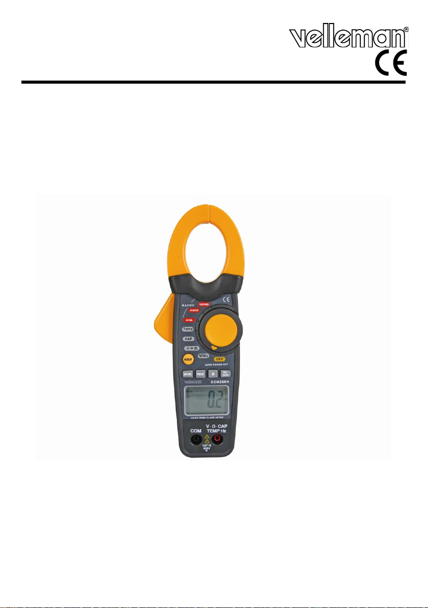
DCM268N
AC/DC TRUE RMS CLAMP METER
AC/DC STROOMTANG - TRUE RMS
PINCE AMPÈREMÉTRIQUE CA/CC - TRUE RMS
AC/DC-STROMZANGE - TRUE RMS
PINZA AMPERIMÉTRICA AC/DC - TRUE RMS
USER MANUAL 3
GEBRUIKERSHANDLEIDING 8
NOTICE D’EMPLOI 13
MANUAL DEL USUARIO 18
BEDIENUNGSANLEITUNG 23
Page 2
DCM268N
Figure 1
00 (28/11/2008) 2 Velleman
®
Page 3
DCM268N
User manual
1. Introduction
To all residents of the European Union
Important environmental information about this product
If in doubt, contact your local waste disposal authorities.
Thank you for choosing Velleman! Please read the manual thoroughly before bringing this
device into service. If the device was damaged in transit, don't install or use it and contact
your dealer.
2. Safety Instructions
• Damage caused by disregard of certain guidelines in this manual is not covered by the
warranty and the dealer will not accept responsibility for any ensuing defects or problems.
• Note that damage caused by user modifications to the device is not covered by the
warranty.
• All modifications of the device are forbidden for safety reasons.
• Caution: risk of electroshock when measuring voltages > 35VDC, 25VAC, currents > 10mA,
AC power lines with inductance load and AC power lines with fluctuating power.
3. General Guidelines
• Protect this device from shocks and abuse. Avoid brute force when operating.
• Familiarise yourself with the functions of the device before actually using it.
• Only use the device for its intended purpose. Using the device in an unauthorised way will
void the warranty.
• Do not store or use the devices in places with high humidity or temperature, places where
combustible or explosive gasses reside or near strong magnetic fields.
• Only use the included test leads. When damaged, replace them with test leads of the same
type and with the same specifications.
• Always verify that all connections are reliable and safe.
• Before measuring, always check the selected range. Always use the device within its
specified range.
• Always discharge capacitors and remove power from the device under test before
performing diode, resistance or continuity test.
This symbol on the device or the package indicates that disposal of the device
after its lifecycle could harm the environment.
Do not dispose of the unit (or batteries) as unsorted municipal waste; it should
be taken to a specialized company for recycling.
This device should be returned to your distributor or to a local recycling service.
Respect the local environmental rules.
For indoor use only. Keep this device away from rain, moisture, splashing and
dripping liquids. Protect the device against extreme heat (e.g. direct sunlight,
heater …) and dust.
Keep the device away from children and unauthorised users.
Risk of electric shock.
Improper use of this device can cause damage, shock, injury or death.
Be very careful when measuring live circuits.
DO NOT disassemble or open the cover. No user-serviceable parts inside.
Refer to an authorized dealer for service and/or spare parts.
00 (28/11/2008) 3 Velleman
®
Page 4
DCM268N
• Avoid body contact with ground potential (e.g. metallic terminals, output sockets, lead
clamp…) while measuring. Make sure to be electrically insulated from ground during
measurement.
• Calibration and repair must be performed by a qualified technician. Refer to your local
dealer.
4. Features
• true RMS measurement of AC current and voltage
• large 4000 count LCD display with bar graph
• peak-hold function to record min. and max. readings for current and voltage
• data-hold function
• DCV (0.1mV~ 600V) and ACV (0.1mV~600V) measurements
• ACA and DCA (0.01~1000A) current measurements
• max. Ø for conductor: 30mm
• resistance measurements: 0.1~40Mohm
• frequency measurements: 0.001~4KHz
• capacitance measurement: 0.001nF~40mF
• temperature measurements: -40°C to 1,000°C
• diode test, continuity test and backlight
• K-type thermocouple measuring range: from -20°C to 1000°C
• optional probes (not incl.): SONDE890, SONDE8264
• safety: indoor use only (overvoltage Cat. III 600V)
5. Overview
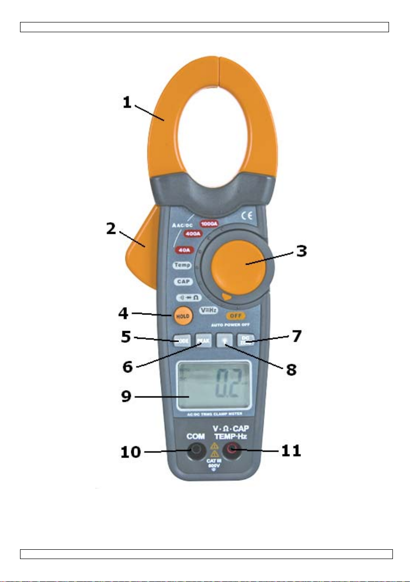
Refer to the drawings on page 2 of this manual.
1 current clamp 7 DCA zero button
2 clamp trigger 8 backlight on/off button
3 rotary function switch 9 LCD display
4 data hold button 10 COM jack
5 mode select button 11 V··CAP·TEMP·HZ jack
6 peak hold button
6. Operation
GENERAL
• When the range of the measured signal is unknown, start measurement in auto-range
mode, and then select range according to indicated value.
• The display shows “OL” when the present range limit is exceeded. Select a higher range
to continue measurement.
• Do not measure voltages > 600 V or current higher than 1000A. Never turn the rotary
function switch [3] during measurement.
• The device will go in sleep mode when no activity is detected for ±20 min.
• For all measurements: pressing the data hold button [4] freezes the currently measured
value until the data hold button [4] is pressed again. The hold-mode is indicated by the
H-symbol in the display.
• To switch on the backlight, press the backlight button [8], to switch it off, press the
backlight button [8] again. The use of backlight will reduce battery life.
• Peak hold function: for AC measurements, pressing the peak hold button [6] once will
show only the maximum measured value on the display [9], indicated with a P
indicator. Pressing the peak hold button [6] again will show only the minimum measured
value on the display [9], indicated with a P
press and hold the peak hold button [6] for ±3 seconds until the P
MIN indicator. To exit the peak hold function,
MAX or PMIN indicator
disappears.
00 (28/11/2008) 4 Velleman
MAX
®
Page 5

DCM268N
AC (TRUE RMS)/DC VOLTAGE MEASUREMENT
• Connect the red test lead to the V··CAP·TEMP·HZ jack [11] and the black lead to the
COM jack [10].
• Set the rotary function switch [3] in the
position.
• Use the mode button [5] to choose between AC and DC voltage.
• Connect the test leads parallel to the source being measured.
• Read the voltage value on the LCD display [9] along with the polarity of the red lead
connection.
• For AC measurement, press the peak hold button [6] to hold either maximum or
minimum measured value (see Peak hold function).
AC (TRUE RMS)/DC CURRENT MEASUREMENT
• Make sure no test leads are connected to the V··CAP·TEMP·HZ jack [11] or COM jack
[10].
• Set the rotary switch [3] in the desired range (
, or ). If the
current to be measured is unknown beforehand, set the range switch in the highest range
position and then reduce gradually until the ideal resolution is obtained.
• Use the mode button [5] to choose between AC and DC current.
• For DC current measurements, press the DCA zero button [7] once to reset the display to
zero for relative measurements (indicated with
in the display).
• Press the trigger [2] to open the jaws [1] of the clamp. Enclose a single conductor within
the clamp and release the trigger [2]. Enclosing multiple conductors at the same time will
result in faulty measurements. For accurate measurements, always keep the jaws closed
during measuring.
• Read the current value on the LCD display.
• Note that when measuring large currents, a buzzing sound may be heard coming from the
jaws. This is normal behaviour which does not influence the measurement accuracy.
RESISTANCE, AUDIBLE CONTINUITY and DIODE TEST
• Connect the red test lead to the V··CAP·TEMP·HZ jack [11] and the black lead to the
COM jack [10].
• Set the rotary switch [3] in the
position.
• Make sure there is no voltage on the circuit/component under test.
• For resistance test press the mode button [5] until the symbol appears (default) in the
display. Connect the test leads to the resistor to be measured and read the value in the
LCD display. Disconnect one side of the device under test to avoid interference from the
rest of the circuit.
• For continuity test, press the mode button [5] until the
symbol appears in the
display. Connect the test leads to the circuit to be measured and read the value in the
LCD display. When the resistance is <35, a continuity buzzer will sound.
Note:
test current: <1mA
• For diode/transistors/ semiconductors/… measurements, press the mode button [5] until
the
symbol appears in the display. During measurement, a current is sent through
the semiconductor junction and the voltage drop is measured. When the junction passes
the test, indicated forward voltage will be 0.4~0.9V while reverse voltage will indicate
“OL”. When the diode is short circuited, both readings will be ±0mV; when open, both
measurements will show “OL”.
Note:
CAPACITY TEST
forward DC current: 0.3mA typical, open circuit voltage: 1.5VDC
• Connect the red test lead to the V··CAP·TEMP·HZ jack [11] and the black lead to the
COM jack [10].
• Set the rotary switch [3] in the
00 (28/11/2008) 5 Velleman
position.
®
Page 6
DCM268N
• Make sure there is no voltage on the circuit under test by discharging capacitors prior to
measurement.
• Connect the test leads to the capacitor to be measured and read the value in the LCD
display.
FREQUENCY measurement
• Connect the red test lead to the V··CAP·TEMP·HZ jack [11] and the black lead to the
COM jack [10].
• Set the rotary function switch [3] in the
position.
• Press and hold the mode button [5] for ±3 seconds until the frequency range is indicated
in the display.
• Connect the test leads to the circuit under test and read the value in the LCD display.
TEMPERATURE
• Set the rotary switch [3] in the
position. Select °C or °F with the mode select
button [5], the selection is indicated in the display.
• Insert the side of the temperature probe adapter marked with “+” in the
V··CAP·TEMP·HZ jack [11] and the other side (“-”) in the COM jack [10].
• If not done already, insert the K-type probe into the probe adapter (only one way
possible).
• Hold the probe head to the device under test for ±30s and read the temperature in the
LCD display.
• Do not change the rotary function switch when the thermocouple is connected to the
meter.
7. Battery
• When the low battery indication ( ) appears, replace the internal battery.
• Always disconnect test leads and set the rotary switch [3] in the
position when
replacing the battery. Do not us the device without batteries installed.
• The battery cover is located on the back of the device and is closed with one screw. Remove
the screw and open the battery compartment.
• Remove the battery and insert a new 9V battery following the polarity as indicated in the
battery holder. Only use a new battery of the same type and specifications.
• Reinstall the cover and secure it with the screw.
• Remove the battery when the device will not be used for a long time to avoid leakage.
• Do not recharge non-rechargeable batteries and do not throw in fire as they may explode.
WARNING: handle batteries with care, observe warnings on battery
casing. Dispose of batteries in accordance with local regulations.
Keep batteries away from children.
Use this device with original accessories only. Velleman nv cannot be held
responsible in the event of damage or injury resulted from (incorrect) use of this
device.
For more info concerning this product, please visit our website www.velleman.eu
The information in this manual is subject to change without prior notice.
.
00 (28/11/2008) 6 Velleman
®
Page 7

DCM268N
Technical specifications
DC voltage 0.4/4/40/400/600V
basic accuracy ±(1.5% of rdg + 2 digits) / ±(0.8% of rdg + 2 digits) for 0.4V range
/ ±(2.0% of rdg + 2 digits) for 600V range
input impedance 10Mohm
maximum input 600V
AC voltage 0.4/4/40/400/600V TRUE RMS
basic accuracy ±(1.5% of rdg + 8 digits) / ±(1.0% of rdg + 10 digits) for 0.4V
range / ±(2.0% of rdg + 8 digits) for 600V range
input impedance 10Mohm
frequency range 50-60Hz
maximum input 600V
DC current 40/400/1000V
basic accuracy ±(2.8% of rdg + 10 digits) for 40A range / ±(2.8% of rdg + 8 digits)
for 400A range / ±(3.0% of rdg + 8 digits) for 1000A range
AC current 40/400/1000A TRUE RMS
basic accuracy ±(2.8% of rdg + 10 digits) for 40A range / ±(2.8% of rdg + 8 digits)
for 400A range / ±(3.0% of rdg + 8 digits) for 1000A range
resistance 400/4K/40K/400K/4M/40M
basic accuracy ±(1.0% of rdg + 4 digits) for 400ohm range / ±(1.5% of rdg + 2
digits) for 4K~400K range / ±(2.5% of rdg + 5 digits) for 4M range /
±(3.5% of rdg + 10 digits) for 40M range
overload protection 15s max. 250V (all ranges)
capacitance 4n/40n/400n/4µ/40µ/400µF/4mF/40mF
accuracy ±(5.0% of rdg + 30 digits) for 4nF range / ±(5.0% of rdg + 20
digits) for 40nF range / ±(3.0% of rdg + 5 digits) for 400nF~40µF
range / ±(4.0% of rdg + 10 digits) for 400µF range / ±(5.0% of rdg
+ 10 digits) for 4mF~40mF range
frequency 4,000KHz
basic accuracy ±(1.5% of rdg + 2 digits)
overload protection 15s max. 250V (all ranges)
temperature -40°C~1,000°C
basic accuracy ±(2.5% of rdg + 3°C)
maximum display 3999
LCD display size 22 x 35 mm
power supply 1 x 9V battery (incl.)
dimensions 229 x 80 x 49mm
weight (with battery) ±303g
00 (28/11/2008) 7 Velleman
®
Page 8

DCM268N
Gebruikershandleiding
1. Inleiding
Aan alle ingezetenen van de Europese Unie
Belangrijke milieu-informatie betreffende dit product
Hebt u vragen, contacteer dan de plaatselijke autoriteiten inzake verwijdering.
Dank u voor uw aankoop! Lees deze handleiding grondig voor u het toestel in gebruik
neemt. Werd het toestel beschadigd tijdens het transport, installeer het dan niet en
raadpleeg uw dealer.
2. Veiligheidsinstructies
• De garantie geldt niet voor schade door het negeren van bepaalde richtlijnen in deze
handleiding en uw dealer zal de verantwoordelijkheid afwijzen voor defecten of problemen
die hier rechtstreeks verband mee houden.
• Schade door wijzigingen die de gebruiker heeft aangebracht aan het toestel vallen niet
onder de garantie.
• Om veiligheidsredenen mag de gebruiker geen wijzigingen aanbrengen aan het toestel.
• LET OP: elektrocutiegevaar tijdens het meten van een spanning > 35 VDC, 25 VAC, een
stroom > 10 mA, AC elektrische leidingen met een inductielast en AC elektrische leidingen
met een fluctuerende stroom.
3. Algemene richtlijnen
• Bescherm de stroomtang tegen schokken en vermijd brute kracht tijdens de bediening.
• Leer eerst de functies van de stroomtang kennen voor u haar gaat gebruiken.
• Gebruik de stroomtang enkel waarvoor zij gemaakt is. Bij onoordeelkundig gebruik
vervalt de garantie.
• Vermijd gebruik van de stroomtang in een vochtige en warme omgeving, of in de buurt van
brandbare stoffen of elektromagnetische velden.
• Gebruik enkel de meegeleverde testsnoeren en vervang ze door identieke exemplaren.
• Ga voor elke meting na of de aansluitingen correct en veilig zijn.
• Stel het toestel op het correcte bereik in voor elke meting.
• Raak tijdens het meten geen circuit (bv. terminals, stopcontacten, enz.) onder stroom aan.
Zorg ervoor dat u tijdens het meten geïsoleerd bent.
• Overschrijd nooit de waarden vermeld achteraan de handleiding.
Dit symbool op het toestel of de verpakking geeft aan dat, als het na zijn
levenscyclus wordt weggeworpen, dit toestel schade kan toebrengen aan het
milieu. Gooi dit toestel (en eventuele batterijen) niet bij het gewone
huishoudelijke afval; het moet bij een gespecialiseerd bedrijf terechtkomen voor
recyclage. U moet dit toestel naar uw verdeler of naar een lokaal recyclagepunt
brengen. Respecteer de plaatselijke milieuwetgeving.
Enkel voor gebruik binnenshuis. Bescherm de stroomtang tegen regen,
vochtigheid, extreme temperaturen, stof en opspattende vloeistoffen.
Houd de stroomtang uit de buurt van kinderen en onbevoegden.
Elektrocutiegevaar tijdens het gebruik van deze multimeter. Wees
voorzichtig tijdens het meten van een circuit onder stroom.
De stroomtang mag noooit geopend worden. Vervang geen onderdelen en bestel
eventuele reserveonderdelen bij uw dealer.
00 (28/11/2008) 8 Velleman
®
Page 9
DCM268N
• Laat de stroomtang ijken en repareren door een geschoold technicus. Neem contact op met
uw dealer.
4. Eigenschappen
• meting van true rms-waarde voor AC-stroom en -spanning
• groot lcd-scherm (4000 counts) met bargraph
• peakholdfunctie voor minimale en maximale spanning/stroom
• data-hold functie
• spanningsmetingen van DCV (0,1 mV ~ 600 V) en ACV (0,1 mV ~ 600 V)
• stroommetingen van ACA en DCA (0,01 ~ 1000 A)
• max. Ø van de geleider: 30 mm
• weerstandsmetingen: 0,1 ~ 40 M
• frequentiemetingen: 0,001 ~ 4 kHz
• capaciteitsmetingen: 0,001 nF ~ 40 mF
• temperatuurmetingen: -40°C ~ 1.000°C
• diode- en continuïteitstest en achtergrondverlichting
• meetbereik K-thermokoppel: -20°C ~ 1.000°C
• optionele sondes (niet meegelev.): SONDE890, SONDE8264
• veiligheid: enkel voor gebruik binnenshuis (overspannin Cat. III 600 V)
5. Omschrijving
Raadpleeg de figuur op pagina 2 van deze handleiding.
1 stroombek 7 DCA-nultoets
2 trekker 8 achtergrondverlichting
3 functieschakelaar 9 lcd-scherm
4 toets data-hold 10 COM-ingangsbus
5 MODE-toets 11 V··CAP·TEMP·HZ-ingangsbus
6 toets peak-hold
6. Gebruik
ALGEMEEN
• Indien u het bereik niet kent, start de meting met de automatische bereikinstelling en
kies het gepaste bereik aan de hand van de eerste meetresultaten.
• De display geeft ‘OL’ weer indien het bereik overschreden wordt. Selecteer een hoger
bereik.
• Meet geen spanning > 600 V of stroom > 1.000 A. Draai niet aan de functieschakelaar
[3] tijdens het meten.
• Het toestel schakelt naar stand-by na 20 minuten inactiviteit.
• Voor alle metingen: Druk op de vergrendeltoets [4] om de uitlezing op de display te
bevriezen (de display geeft ‘H’ weer). Druk opnieuw om verder te gaan.
• Druk op de achtergrondverlichtingstoets [8] om achtergrondverlichting in of uit te
schakelen.
• Peakholdfunctie: Voor alle AC-metingen, druk eenmaal op de toets PEAK [6] om de
maximale waarde weer te geven (op de display verschijnt P
om de minimale waarde weer te geven (op de display verschijnt P
[6] gedurende 3 seconden ingedrukt om de functie te verlaten.
METEN VAN AC- (TRUE RMS) EN DC-SPANNING
• Koppel het rode meetsnoer aan de V··CAP·TEMP·Hz-ingangsbus [11] en het zwarte
meetsnoer aan de COM-ingangsbus [10].
• Plaats de functieschakelaar [3] op
.
• Kies tussen AC- en DC-spanning met de MODE-toets [5].
• Sluit de sondes in parallel aan het te meten circuit.
00 (28/11/2008) 9 Velleman
MAX), druk een tweede keer
MIN). Houd toets PEAK
®
Page 10

DCM268N
• Lees de waarde en de polariteit van het rode meetsnoer van de display [9] af.
• Voor metingen van de AC-spanning, druk op de PEAK-toets [6] om de maximale of de
minimale waarde op de display weer te geven (zie ‘Peakholdfunctie’).
METEN VAN AC- (TRUE RMS) EN DC-STROOM
• Zorg ervoor dat er geen enkel meetsnoer aan ingangsbussen [10][11] is aangesloten.
• Plaats de functieschakelaar [3] op het gewenste bereik (
, of ). Indien u het
bereik niet kent, start de meting op het hoogste bereik en kies het gepaste bereik aan de
hand van de eerste meetresultaten.
• Kies tussen AC- en DC-stroom met de MODE-toets [5].
• Voor metingen van DC-stroom, druk op de DCA-nultoets [7] om de uitlezing te wissen
(op de display verschijnt
).
• Open de kaken [1] met de trekker [2] en sluit een enkele geleider volledig tussen de
kaken. Laat de trekker [2] los. Het meten van meerdere geleiders tegelijkertijd geeft een
verkeerde uitlezing weer. Houd de kaken gesloten tijdens het meten.
• Lees de waarde van het rode meetsnoer van de display [9] af.
• Tijdens het meten van een hoge stroom kan de stroomtang zoemen. Dit is normaal en
beïnvloedt de meting niet.
METEN VAN WEERSTAND, DOORVERBINDING EN DIODE
• Koppel het rode meetsnoer aan de V··CAP·TEMP·Hz-ingangsbus [11] en het zwarte
meetsnoer aan de COM-ingangsbus [10].
• Plaats de functieschakelaar [3] op
.
• Zorg dat het circuit niet onder stroom staat.
• Voor de weerstandstest, druk op de MODE-toets [5] tot op de display verschijnt.
Koppel de meetsnoeren aan de weerstand en lees de waarde van de display [9] af.
Ontkoppel een zijde van het te meten circuit om storingen te vermijden.
• Voor de doorverbindingstest, druk op de MODE-toets [5] tot
op de display verschijnt.
Koppel de meetsnoeren aan het circuit en lees de waarde van de display [9] af. Bij een
weerstand < 35 piept de multimeter.
Opmerking
• Voor de diode-, transistor- en halfgeleidertest, druk op de MODE-toets [5] tot
: teststroom:< 1 mA.
op de
display verschijnt. Een goede diode heeft een directe spanning tussen 0,4 ~ 0,9 V. Bij een
omgekeerde aansluiting en bij een open diode verschijnt ‘OL’, bij een kortsluiting in de
diode verschijnt een waarde van ‘± 0 mV’.
Opmerking
METEN VAN CAPACITEIT
: directe DC-stroom: 0,3 mA typisch, spanning open circuit: 1,5 VDC.
• Koppel het rode meetsnoer aan de V··CAP·TEMP·Hz-ingangsbus [11] en het zwarte
meetsnoer aan de COM-ingangsbus [10].
• Plaats de functieschakelaar [3] op
.
• Zorg dat het circuit niet onder stroom staat door eerst alle condensatoren te ontladen.
• Koppel de sondes aan de te meten condensator en lees de waarde van de display [9] af.
METEN VAN FREQUENTIE
• Koppel het rode meetsnoer aan de V··CAP·TEMP·Hz-ingangsbus [11] en het zwarte
meetsnoer aan de COM-ingangsbus [10].
• Plaats de functieschakelaar [3] op
.
• Houd de MODE-toets [5] gedurende 3 seconden ingedrukt tot het frequentiebereik op de
display verschijnt.
• Koppel de sondes aan het te meten circuit en lees de waarde van de display [8] af.
METEN VAN DE TEMPERATUUR
• Plaats de functieschakelaar [3] op
. Selecteer °C of °F met de MODE-toets [5]. Uw
keuze wordt op de display [9] weergegeven.
• Koppel de positieve zijde van de temperatuursonde aan de V··CAP·TEMP·Hz-ingangsbus
[11] en de negatieve zijde aan de COM-ingangsbus [10].
00 (28/11/2008) 10 Velleman
®
Page 11

DCM268N
• Koppel de thermokoppel aan de stroomtang.
• Houd de temperatuursonde gedurende ± 30 seconden tegen het te meten object en lees
de waarde van de display [9] af.
• Draai niet aan de functieschakelaar terwijl de temperatuursonde aan de meettang
gekoppeld is.
7. De batterij
• Vervang de batterij van zodra de aanduiding voor zwakke batterij ( ) op de display
verschijnt.
• Ontkoppel de testsnoeren en plaats de functieschakelaar [3] op
alvorens de batterij te
vervangen. Gebruik geen meettang zonder batterij.
• Maak de schroef los en open het batterijvak achteraan de stroomtang.
• Verwijder de oude batterij en plaats een nieuwe 9 V-batterij van hetzelfde type. Respecteer
de polariteitsaanduidingen.
• Sluit het batterijvak en span de schroef aan.
• Verwijder de batterij uit de stroomtang na gebruik.
• Herlaad geen alkalinebatterijen en gooi ze nooit in het vuur.
LET OP: Volg de richtlijnen op de verpakking van de batterij. Houd de
batterij buiten bereik van kinderen.
8. Technische specificaties
DC-spanning 0,4/4/40/400/600 V
basisnauwkeurigheid ±(1,5 % vd uitl. + 2 digits) / ±(0,8 % vd uitl. + 2 digits) voor 0,4 V-
ingangsimpedantie 10 M
maximale ingang 600 V
AC-spanning 0,4/4/40/400/600 V true rms
basisnauwkeurigheid ±(1,5 % vd uitl. + 8 digits)/±(1,0 % vd uitl. + 10 digits) voor 0,4 V-
ingangsimpedantie 10 M
frequentiebereik 50 ~ 60 Hz
maximale ingang 600 V
DC-stroom 40/400/1.000 V
basisnauwkeurigheid ±(2,8 % vd uitl. + 10 digits) voor 40 A-bereik/±(2,8 % vd uitl. + 8
AC-stroom 40/400/1.000 A true rms
basisnauwkeurigheid ±(2,8 % vd uitl. + 10 digits) voor 40 A-bereik/±(2,8 % vd uitl. + 8
weerstand 400/4 k/40 k/400 k/4 M/40 M
basisnauwkeurigheid ±(1,0 % vd uitl. + 4 digits) voor 400 -bereik/±(1,5 % vd uitl. + 2
beveiliging
overbelasting
bereik/±(2,0 % vd uitl. + 2 digits) voor 600 V-bereik
bereik/±(2,0 % vd uitl. + 8 digits) voor 600 V-bereik
digits) voor 400 A-bereik/±(3,0 % vd uitl. + 8 digits) voor 1.000 Abereik
digits) voor 400 A-bereik/±(3,0 % vd uitl. + 8 digits) voor 1.000 Abereik
digits) voor 4k ~ 400k-bereik/±(2,5 % vd uitl. + 5 digits) voor 4 Mbereik/±(3,5 % vd uitl. + 10 digits) voor 40 M-bereik
15 s max. 250 V (alle bereiken)
00 (28/11/2008) 11 Velleman
®
Page 12

DCM268N
capaciteit 4 n/40 n/400 n/4 µ/40 µ/400 µF/4 mF/40 mF
basisnauwkeurigheid ±(5,0 % vd uitl. + 30 digits) voor 4 nF-bereik/±(5,0 % vd uitl. + 20
digits) voor 40 nF-bereik/±(3,0 % vd uitl. + 5 digits) voor
400 nF ~ 40 µF-bereik/±(4,0 % vd uitl. + 10 digits) voor 400 µF-
bereik/±(5,0 % vd uitl. + 10 digits) voor 4 mF ~ 40 mF-bereik
frequentie 4.000 kHz
basisnauwkeurigheid ±(1,5 % vd uitl. + 2 digits)
beveiliging
overbelasting
15 s max. 250 V (alle bereiken)
temperatuur -40°C ~ 1.000°C
basisnauwkeurigheid ±(2,5 % vd uitl. + 3°C)
maximale uitlezing 3.999
afmetingen display 22 x 35 mm
voeding 1 x 9 V-batterij (meegelev.)
afmetingen 229 x 80 x 49 mm
gewicht (met batterij) ± 303 g
Gebruik dit toestel enkel met originele accessoires. Velleman nv is niet
aansprakelijk voor schade of kwetsuren bij (verkeerd) gebruik van dit toestel.
Voor meer informatie omtrent dit product, zie www.velleman.eu
. De informatie in
deze handleiding kan te allen tijde worden gewijzigd zonder voorafgaande
kennisgeving.
00 (28/11/2008) 12 Velleman
®
Page 13

DCM268N
NOTICE D’EMPLOI
1. Introduction
Aux résidents de l'Union européenne
Des informations environnementales importantes concernant ce produit
Ce symbole sur l'appareil ou l'emballage indique que l’élimination d’un appareil en fin de vie
En cas de questions, contacter les autorités locales pour élimination.
Nous vous remercions de votre achat ! Lire la présente notice attentivement avant la mise
en service de l’appareil. Si l’appareil a été endommagé pendant le transport, ne pas
l’installer et consulter votre revendeur.
2. Prescriptions de sécurité
• La garantie ne s’applique pas aux dommages survenus en négligeant certaines directives
de cette notice et votre revendeur déclinera toute responsabilité pour les problèmes et les
défauts qui en résultent.
• Les dommages occasionnés par des modifications par le client ne tombent pas sous la
garantie.
• Toute modification est interdite pour des raisons de sécurité.
• Attention : Risque d’électrochoc lors de mesures de tensions > 35 VCC, 25 VCA, courants
> 10 mA, lignes électriques CA avec charge inductive et lignes électriques CA avec
fluctuations.
3. Directives générales
• Protéger la pince contre les chocs et la traiter avec circonspection pendant l’installation et
l’opération.
• Se familiariser avec le fonctionnement avant l’usage.
• N’utiliser la pince qu’à sa fonction prévue. Un usage impropre annule d'office la garantie.
• Stocker la pince dans un endroit sec et propre, et à l’écart de hautes températures, de gaz
explosifs ou de champs magnétiques.
• N’utiliser cette pince qu’avec les sondes incluses. Remplacer les sondes par des sondes
identiques.
• S’assurer que les connexions soient dûment établies.
• Sélectionner la gamme avant chaque mesure.
• Éviter de toucher des cosses métalliques, les sondes, etc. pendant la mesure. Veiller à vous
isoler électriquement.
00 (28/11/2008) 13 Velleman
peut polluer l'environnement. Ne pas jeter un appareil électrique ou électronique
(et des piles éventuelles) parmi les déchets municipaux non sujets au tri
sélectif ; une déchèterie traitera l’appareil en question. Renvoyer les
équipements usagés à votre fournisseur ou à un service de recyclage local. Il
convient de respecter la réglementation locale relative à la protection de
l’environnement.
Pour usage à l’intérieur uniquement. Protéger la pince contre la pluie, l’humidité,
les températures extrêmes, la poussière et les projections d’eau.
Garder la pince hors de la portée de personnes non qualifiées et de jeunes
enfants.
Risque d’électrochoc pendant l’utilisation de cette pince
ampèremétrique. Procéder avec précaution lors de mesure d’un circuit sous
tension.
Ne jamais ouvrir ni démonter la pince. Il n’y a aucune pièce maintenable par
l’utilisateur. Commander des pièces de rechange éventuelles chez votre
revendeur.
®
Page 14

DCM268N
• Ne jamais appliquer une tension ou un courant excédant les spécifications mentionnées à la
fin de cette notice.
• Confier l’étalonnage et l’entretien à un technicien qualifié.
4. Caractéristiques
• mesure de la valeur TRMS pour la tension et le courant RMS
• afficheur LCD grand format (4.000 points) avec bargraph
• fonction de gel de l’affichage de la valeur MIN/MAX de courant/tension
• fonction de gel de l’affichage
• mesures de tension CC (0,1 mV ~ 600 V) et CA (0,1 mV ~ 600 V)
• mesures de courant CA et CC (0,01 ~ 1.000 A)
• diamètre max. des conducteurs : 30 mm
• mesures de résistances : 0,1 ~ 40 M
• mesures de fréquences : 0,001 ~ 4 kHz
• mesures de capacité : 0,001 nF ~ 40 mF
• mesures de température : -40°C ~ 1.000°C
• test de diodes et de continuité, rétro-éclairage
• plage de mesure du thermocouple type K : -20°C ~ 1.000°C
• sondes de mesure optionnelles (non incl.) : SONDE890, SONDE8264
• sécurité : pour usage à l'intérieur uniquement (surtensions Cat. III 600 V)
5. Descriptions
Consulter l’illustration à la page2 de cette notice.
1 mâchoires 7 touche de réinitialisation CCA
2 gâchette 8 touche de rétro-éclairage
3 sélecteur de fonction rotatif 9 afficheur LCD
4 touche de gel d’affichage 10 prise COM
5 touche MODE 11 prise V··CAP·TEMP·Hz
6 touche PEAK
6. Emploi
EN GÉNÉRAL
• Démarrer la mesure avec la fonction d’instauration de gamme automatique lorsque
l’étendue de la gamme est inconnue.
• Une mesure hors plage est indiquée par « OL ». Sélectionner une gamme supérieure.
• Ne pas mesurer des tensions > 600 V ou des courants > 1.000 mA. Ne jamais tourner le
sélecteur de fonction [3] rotatif lorsqu’une mesure est en cours.
• La pince se met en mode veille après un délai de ± 20 minutes. Enfoncer une touche pour
continuer.
• Pour toutes les mesures, enfoncer la touche de gel d’affichage [4] pour geler la valeur
affichée (l’indication « H » s’affiche). Renfoncer la touche pour continuer.
• Éclairer et éteindre l’afficheur en maintenant enfoncé la touche de rétro-éclairage [8].
• Gel de l’affichage de la valeur MIN/MAX : Pour toutes les mesures CA, enfoncer la
touche PEAK [6] pour afficher la valeur maximale (l’afficheur indique P
touche une deuxième fois pour afficher la valeur minimale (l’afficheur indique P
Quitter la fonction en maintenant enfoncé la touche PEAK [6] pendant ±3 secondes.
MESURE DE TENSIONS CA (TRMS) ET CC
• Veiller à ce qu’aucune sonde n’est connectée aux prises [10][11].
• Placer le sélecteur de fonction rotatif [3] sur la gamme souhaitée (
Démarrer la mesure avec la fonction d’instauration de gamme automatique lorsque
l’étendue de la gamme est inconnue.
• Sélectionner le courant CA ou CC avec la touche MODE [5].
00 (28/11/2008) 14 Velleman
MAX). Enfoncer la
MIN).
, ou ).
®
Page 15

DCM268N
• Pour les mesures de courant CC, enfoncer la touche de réinitialisation CCA [7] pour
effacer l’affichage (l’afficheur indique
).
• Enfoncer la gâchette [2] et ouvrir les mâchoires [1]. Renfermer un seul conducteur dans
les mâchoires [1] et relâcher la gâchette [2]. Ne pas renfermer plusieurs conducteurs
pour éviter les mesures erronées. Tenir les mâchoires fermées pendant la mesure.
• Lire la valeur sur l’afficheur [9].
• La pince peut émettre une tonalité lors de mesures de courants élevés. Ceci est normal et
n’aura pas d’influence sur le résultat de la mesure.
MESURE DE RÉSISTANCE, DE CONTINUITÉ ET TEST DE DIODE
• Insérer la sonde rouge dans la prise V··CAP·TEMP·Hz [11] et la sonde noire dans la
prise COM [10].
• Placer le sélecteur de fonction rotatif [3] sur
.
• Couper le courant vers le circuit.
• Pour tester la résistance, enfoncer la touche MODE [5] jusqu’à l’affichage de l’indication
. Connecter les sondes au circuit et lire la valeur sur l’afficheur [9]. Déconnecter un
côté du circuit à mesurer afin d’éviter les interférences.
• Pour tester la continuité, enfoncer la touche MODE [5] jusqu’à l’affichage de l’indication
. Connecter les sondes au circuit et lire la valeur sur l’afficheur [9]. Une résistance de
< 35 sera indiquée par une tonalité.
Remarque
: courant de test : < 1 mA.
• Pour tester une diode, un transistor ou un semi-conducteur, enfoncer la touche [5]
jusqu’à l’affichage de l’indication
. Une bonne diode affichera une valeur entre
0,4 ~ 0,9 V. Une connexion inversée et une diode ouverte sone indiquées par « OL », la
présence d’un court-circuit affichera une valeur de ± 0 mV.
Remarque
MESURE DE LA CAPACITÉ
: courant CC direct : 0,3 mA typique, tension circuit ouvert : 1,5 VCC.
• Insérer la sonde rouge dans la prise V··CAP·TEMP·Hz [11] et la sonde noire dans la
prise COM [10].
• Placer le sélecteur de fonction rotatif [3] sur
.
• Couper le courant vers le circuit et décharger tous les condensateurs avant chaque
mesure.
• Connecter les sondes au condensateur à mesurer et lire la valeur sur l’afficheur [9].
MESURE DE FRÉQUENCE
• Insérer la sonde rouge dans la prise V··CAP·TEMP·Hz [11] et la sonde noire dans la
prise COM [10].
• Placer le sélecteur de fonction rotatif [3] sur
.
• Maintenir enfoncé la touche MODE [5] pendant ± 3 secondes jusqu’à ce que la gamme de
fréquence s’affiche.
• Connecter les sondes au circuit à mesurer et lire la valeur sur l’afficheur [9].
MESURE DE LA TEMPÉRATURE
• Placer le sélecteur de fonction rotatif [3] sur
et sélectionner l’unité °C ou °F avec la
touche MODE [5]. Votre sélection est affichée.
• Insérer la cathode (+) du thermocouple dans la prise V··CAP·TEMP·Hz [11] et insérer
l’anode (-) dans la prise COM [10].
• Raccorder le thermocouple type K à la pince ampèremétrique.
• Rapprocher le thermocouple de l’objet à mesurer et maintenir pendant ± 30 secondes.
Lire la valeur sur l’afficheur [9].
• Ne pas tourner le sélecteur de fonction rotatif lorsque le thermocouple est connecté à la
pince.
00 (28/11/2008) 15 Velleman
®
Page 16

DCM268N
7. La pile
• Remplacer la pile dès que l’indication de pile faible ( ) s’affiche.
• Déconnecter les sondes et placer le sélecteur de fonction [3] sur
avant le
remplacement. Ne pas utiliser une pince sans piles.
• Desserrer la vis à l’arrière de la pince pour ouvrir le compartiment des piles.
• Retirer la pile et insérer une nouvelle pile en respectant la polarité. N’utiliser qu’une pile
identique.
• Refermer le compartiment de la pile.
• Retirer les piles après usage.
• Ne pas recharger des piles alcalines et ne pas les jeter au feu.
ATTENTION : Observer les directives sur l’emballage des piles. Tenir les
piles à l’écart des enfants.
8. Spécifications techniques
tension CC 0,4/4/40/400/600 V
précision de base ±(1,5 % de l’aff. + 2 digits) / ±(0,8 % de l’aff. + 2 digits) pour la
impédance d’entrée 10 M
entrée maximale 600 V
tension CA 0,4/4/40/400/600 V TRMS
précision de base ±(1,5 % de l’aff. + 8 digits)/±(1,0 % de l’aff. + 10 digits) pour la
impédance d’entrée 10 M
plage de fréquence 50 ~ 60 Hz
entrée maximale 600 V
courant CC 40/400/1.000 V
précision de base ±(2,8 % de l’aff. + 10 digits) pour la gamme 40 A/±(2,8 % de l’aff.
courant CA 40/400/1.000 A TRMS
précision de base ±(2,8 % de l’aff. + 10 digits) pour la gamme 40 A/±(2,8 % de l’aff.
résistance 400/4 k/40 k/400 k/4 M/40 M
précision de base ±(1,0 % de l’aff. + 4 digits) pour la gamme 400 /±(1,5 % de l’aff.
protection
surcharges
capacité 4 n/40 n/400 n/4 µ/40 µ/400 µF/4 mF/40 mF
précision de base ±(5,0 % de l’aff. + 30 digits) pour la gamme 4 nF/±(5,0 % de l’aff.
gamme 0,4 V/±(2,0 % de l’aff. + 2 digits) pour la gamme 600 V
gamme 0,4 V/±(2,0 % de l’aff. + 8 digits) pour la gamme 600 V
+ 8 digits) pour la gamme 400 A/±(3,0 % de l’aff. + 8 digits) pour la
gamme 1.000 A
+ 8 digits) pour la gamme 400 A/±(3,0 % de l’aff. + 8 digits) pour la
gamme 1.000 A
+ 2 digits) pour la gamme 4k ~ 400k/±(2,5 % de l’aff. + 5 digits)
pour la gamme 4 M/±(3,5 % de l’aff. + 10 digits) pour la gamme
40 M
15 s max. 250 V (toutes les gammes)
+ 20 digits) pour la gamme 40 nF/±(3,0 % de l’aff. + 5 digits) pour
la gamme 400 nF ~ 40 µF/±(4,0 % de l’aff. + 10 digits) pour la
gamme 400 µF/±(5,0 % de l’aff. + 10 digits) pour la gamme
4 mF ~ 40 mF
00 (28/11/2008) 16 Velleman
®
Page 17

DCM268N
fréquence 4.000 kHz
précision de base ±(1,5 % de l’aff. + 2 digits)
protection
surcharges
15 s max. 250 V (toutes les gammes)
température -40°C ~ 1.000°C
précision de base ±(2,5 % de l’aff. + 3°C)
affichage maximal 3.999
dimensions afficheur 22 x 35 mm
alimentation 1 pile 9 V (incl.)
dimensions 229 x 80 x 49 mm
poids (avec pile) ± 303 g
N’employer cet appareil qu’avec des accessoires d’origine. SA Velleman ne sera
aucunement responsable de dommages ou lésions survenus à un usage (incorrect)
de cet appareil. Pour plus d’information concernant cet article, visitez notre site
web www.velleman.eu
. Toutes les informations présentées dans cette notice
peuvent être modifiées sans notification préalable.
00 (28/11/2008) 17 Velleman
®
Page 18

DCM268N
MANUAL DEL USUARIO
1. Introducción
A los ciudadanos de la Unión Europea
Importantes informaciones sobre el medio ambiente concerniente a este producto
Respete las leyes locales en relación con el medio ambiente.
Si tiene dudas, contacte con las autoridades locales para residuos.
¡Gracias por haber comprado el DCM268N! Lea atentamente las instrucciones del manual
antes de usarlo. Si el aparato ha sufrido algún daño en el transporte no lo instale y póngase
en contacto con su distribuidor.
2. Instrucciones de seguridad
• Los daños causados por descuido de las instrucciones de seguridad de este manual
• Los daños causados por modificaciones no autorizadas, no están cubiertos por la garantía.
• Por razones de seguridad, las modificaciones no autorizadas del aparato están prohibidas.
• ¡Ojo!: Riesgo de descargas eléctricas al medir tensiones > 35 VCC, 25 VCA, corrientes >
3. Normas generales
• No agite el aparato. Evite usar excesiva fuerza durante el manejo y la instalación.
• Familiarícese con el funcionamiento del aparato antes de utilizarlo.
• Utilice sólo el aparato para las aplicaciones descritas en este manual. Un uso
• Guarde el multímetro en un lugar seco y limpio. No lo exponga a temperaturas elevadas,
• Use sólo el mismo tipo de puntas de prueba que fueron suministradas con su multímetro. Si
• Asegúrese de que haya efectuado las conexiones de manera correcta.
• Seleccione el rango antes de cada medición.
• No toque bornes metálicos, enchufes, etc. durante la medición. Asegúrese de que Ud. se
• Nunca aplique una tensión o una corriente que sea mayor que la tensión o la corriente
• El mantenimiento y la calibración deben ser realizados por personal especializado.
Este símbolo en este aparato o el embalaje indica que, si tira las muestras
inservibles, podrían dañar el medio ambiente. No tire este aparato (ni las pilas, si
las hubiera) en la basura doméstica; debe ir a una empresa especializada en
reciclaje. Devuelva este aparato a su distribuidor o a la unidad de reciclaje local.
Sólo para el uso en interiores. No exponga este equipo a lluvia, humedad,
temperaturas extremas, polvo ni a ningún tipo de salpicadura o goteo.
Mantenga el aparato lejos del alcance de personas no capacitadas y niños.
Riesgo de descargas eléctricas al utilizar este aparato. S Sea cuidadoso al
efectuar mediciones en un circuito conectado a la red.
El usuario no habrá de efectuar el mantenimiento de ninguna pieza. Contacte
con su distribuidor si necesita piezas de recambio.
invalidarán su garantía y su distribuidor no será responsable de ningún daño u otros
problemas resultantes.
10 mA, cables eléctricas CA con carga inductiva y cables CA con fluctuaciones.
desautorizado anula la garantía completamente.
gas explosivo o campos magnéticos.
es necesario, reemplácelas por puntas de prueba idénticas.
aísle eléctricamente.
indicada en las especificaciones de este manual del usuario.
00 (28/11/2008) 18 Velleman
®
Page 19

DCM268N
4. Características
• medición del valor true RMS para la tensión y la corriente RMS
• gran pantalla LCD (4000 puntos) con gráfico de barras
• función de retención del valor de cresta (peak hold) MIN/MAX de corriente/tensión
• retención de lectura (data hold)
• tensión CC (0,1mV~600V) y CA (0,1mV~600V)
• corriente CA y CC (0,01~1000A)
• Ø máx. del conductor: 30 mm
• resistencia: 0,1 ~ 40 M
• frecuencia: 0,001 ~ 4 kHz
• capacidad: 0,001 nF ~ 40 mF
• temperatura: -40°C ~ 1.000°C
• prueba de diodos, de continuidad y retroiluminación
• rango de medición de la sonda tipo "K": -20°C ~ 1.000°C
• sondas opcionales (no incl.): SONDE890, SONDE8264
• seguridad: sólo para el uso en interiores (sobretensiones Cat. III 600V)
5. Descripción
Véase la figura en la página Error! Bookmark not defined. de este manual del usuario.
1 mordazas 7 tecla de reinicialización CCA
2 gatillo 8 tecla de retroiluminación
3 selector de función giratorio 9 pantalla LCD
4 tecla para la retención de lectura (data
10 borne COM
hold)
5 tecla MODE 11 borne V··CAP·TEMP·Hz
6 tecla PEAK
6. Uso
EN GENERAL
• Active la medición con la función de selección automática del rango si no conoce el valor
de antemano.
• Una medición sobre rango se indica por « OL ». Seleccione un rango superior.
• No mida tensiones > 600 V ni corrientes > 1000 mA. Nunca gire el selector de función
[3] mientras que se esté efectuando una medición.
• El aparato se pone en el modo de espera (stand-by) después de ± 20 minutos de
inactividad. Pulse una tecla para continuar.
• Para cualquier medición, pulse la tecla de retención de lectura (data hold) [4] para fijar el
valor visualizado (la indicación « H » se visualiza). Vuelva a pulsar la tecla para continuar.
• Mantenga pulsada la tecla de retroiluminación [8] para activar o desactivarla.
• Función de retención del valor MIN/MAX (peak hold): Para cualquier medición CA,
pulse la tecla PEAK [6] para visualizar el valor máx. (la pantalla indica P
tecla una segunda vez para visualizar el valor mín. (la pantalla indica P
función al mantener pulsada la tecla PEAK [6] durante ±3 segundos.
MEDIR LA TENSIÓN CA (TRMS) Y CC
• Asegúrese de que no esté conectada las puntas de prueba [10][11].
• Ponga el selector de función giratorio [3] sur el rango deseado (
Active la medición con la función de selección automática del rango si no conoce el valor
de antemano.
• Seleccione la corriente CA o CC con la tecla MODE [5].
• Para las mediciones de corriente CC, pulse la tecla de reinicialización CCA [7] para borrar
la visualización (la pantalla indica
00 (28/11/2008) 19 Velleman
).
MAX). Pulse la
MIN). Salga de la
, o ).
®
Page 20

DCM268N
• Pulse el gatillo [2] y abra las mordazas [1]. Vuelva a cerrar un solo conductor de las
mordazas [1] y suelte el gatillo [2]. No cierre varios conductores para evitar mediciones
incorrectas. Mantenga cerradas las mordazas durante la medición.
• Se visualiza el valor en la pantalla [9].
• La pinza puede emitir una señal acústica al medir mediciones de corrientes elevadas. Esto
es normal y no influirá el resultado de la medición.
MEDIR LA RESISTENCIA, LA CONTINUIDAD Y PRUEBA DE DIODOS
• Conecte la punta de prueba roja al borne V··CAP·TEMP·Hz [11] y la punta de prueba
negra al borne COM [10].
• Ponga el selector de función giratorio [3] en
.
• Desconecte la corriente del circuito.
• Para comprobar la resistencia, pulse la tecla MODE [5] hasta que se visualice la
indicación . Conecte las puntas de prueba al circuito. Se visualiza el valor en la pantalla
[9]. Desconecte un lado del circuito que quiere medir para evitar las interferencias.
• Para comprobar la continuidad, pulse la tecla MODE [5] hasta que se visualice la
indicación
. Conecte las puntas de prueba al circuito. Se visualiza el valor en la pantalla
[9]. Una resistencia de < 35 se indica por una señal acústica.
Nota
: corriente de prueba: < 1 mA.
• Para comprobar un diodo, un transistor o un semiconductor, pulse la tecla [5] hasta que
se visualice la indicación
. Un buen diodo visualizará un valor entre 0,4 ~ 0,9 V. Una
conexión invertida y un diodo abierto se indican por « OL ». la presencia de un
cortocircuito se visualizará por un valor de ± 0 mV.
Nota
: corriente CC directa: 0,3 mA típ., tensión circuito abierto: 1,5 VCC.
MEDIR LA CAPACIDAD
• Conecte la punta de prueba roja al borne V··CAP·TEMP·Hz [11] y la punta de prueba
negra al borne COM [10].
• Ponga el selector de función giratorio [3] en
.
• Desconecte la corriente del circuito y descargue todos los condensadores antes de cada
medición.
• Conecte las puntas de prueba al condensador que quiere medir. Se visualiza el valor en la
pantalla [9].
MEDICIÓN DE FRECUENCIA
• Conecte la punta de prueba roja al borne V··CAP·TEMP·Hz [11] y la punta de prueba
negra al borne COM [10].
• Ponga el selector de función giratorio [3] en
.
• Mantenga pulsada la tecla MODE [5] durante ± 3 segundos hasta que el rango de
frecuencia se visualice.
• Conecte las puntas de prueba al circuito que quiere medir. Se visualiza el valor en la
pantalla [9].
MEDIR LA TEMPERATURA
• Ponga el selector de función giratorio [3] en
y seleccione la unidad °C o °F con la
tecla MODE [5]. Se visualiza su elección.
• Introduzca el cátodo (+) del termopar en el borne V··CAP·TEMP·Hz [11] e introduzca el
ánodo (-) en el borne COM [10].
• Conecte el termopar tipo « K » a la pinza amperimétrica.
• Ponga el termopar durante ± 30 segundos en el objeto que quiere medir. Se visualiza el
valor en la pantalla [9].
• No gire el selector de función si el termopar está conectado a la pinza amperimétrica.
00 (28/11/2008) 20 Velleman
®
Page 21

DCM268N
7. La pila
• Reemplace las pilas en cuanto se visualice la indicación de pila baja ( ).
• Desconecte las puntas de prueba y ponga el selector de función [3] en
antes de
reemplazar las pilas. No utilice una pinza amperimétrica sin pilas.
• Desatornille el tornillo de la parte trasera de la pinza amperimétrica para abrir el
compartimiento de pilas.
• Saque la pila e introduzca una nueva pila. Respete la polaridad. Utilice sólo pilas idénticas.
• Cierre el compartimiento de pilas.
• Saque las pilas después del uso.
• Nunca recargue pilas alcalinas. No eche la pila al fuego.
¡OJO!: Respete las advertencias del embalaje. Mantenga las pilas lejos del
alcance de niños.
8. Especificaciones
tensión CC 0,4/4/40/400/600 V
precisión básica ±(1,5 % lectura + 2 dígitos) / ±(0,8 % lectura + 2 dígitos) para el
impedancia de
entrada
entrada máx. 600 V
tensión CA 0,4/4/40/400/600 V TRMS
precisión básica ±(1,5 % lectura + 8 dígitos)/±(1,0 % lectura + 10 dígitos) para el
impedancia de
entrada
rango de frecuencia 50 ~ 60 Hz
entrada máx. 600 V
corriente CC 40/400/1.000 V
precisión básica ±(2,8 % lectura + 10 dígitos) para el rango de 40 A/±(2,8 % lectura
corriente CA 40/400/1.000 A TRMS
precisión básica ±(2,8 % lectura + 10 dígitos) para el rango de 40 A/±(2,8 % lectura
resistencia 400/4 k/40 k/400 k/4 M/40 M
precisión básica ±(1,0 % lectura + 4 dígitos) para el rango de 400 /±(1,5 % lectura
protección contra
sobrecarga
capacidad
rango de 0,4 V/±(2,0 % lectura + 2 dígitos) para el rango de 600 V
10 M
rango de 0,4 V/±(2,0 % lectura + 8 dígitos) para el rango de 600 V
10 M
+ 8 dígitos) para el rango de 400 A/±(3,0 % lectura + 8 dígitos) para
el rango de 1.000 A
+ 8 dígitos) para el rango de 400 A/±(3,0 % lectura + 8 dígitos) para
el rango de 1.000 A
+ 2 dígitos) para el rango de 4k ~ 400k/±(2,5 % lectura + 5 dígitos)
para el rango de 4 M/±(3,5 % lectura + 10 dígitos) para el rango de
40 M
15 s máx. 250 V (todos los rangos)
4 n/40 n/400 n/4 µ/40 µ/400 µF/4 mF/40 mF
00 (28/11/2008) 21 Velleman
®
Page 22

DCM268N
precisión básica ±(5,0 % lectura + 30 dígitos) para el rango de 4 nF/±(5,0 % lectura
+ 20 dígitos) para el rango de 40 nF/±(3,0 % lectura + 5 dígitos)
para el rango de 400 nF ~ 40 µF/±(4,0 % lectura + 10 dígitos) para
el rango de 400 µF/±(5,0 % lectura + 10 dígitos) para el rango de
4 mF ~ 40 mF
frecuencia 4.000 kHz
precisión básica ±(1,5 % lectura + 2 dígitos)
protección contra
sobrecarga
15 s máx. 250 V (todos los rangos)
temperatura -40°C ~ 1.000°C
precisión básica ±(2,5 % lectura + 3°C)
display máx. 3.999
tamaño display LCD
22 x 35 mm
alimentación 1 pila de 9 V (incl.)
dimensiones 229 x 80 x 49 mm
Peso (con pila) ± 303 g
Utilice este aparato sólo con los accesorios originales. Velleman NV no será
responsable de daños ni lesiones causados por un uso (indebido) de este aparato.
Para más información sobre este producto, visite nuestra página web
www.velleman.eu
. Se pueden modificar las especificaciones y el contenido de este
manual sin previo aviso.
00 (28/11/2008) 22 Velleman
®
Page 23

DCM268N
BEDIENUNGSANLEITUNG
1. Einführung
An alle Einwohner der Europäischen Union
Wichtige Umweltinformationen über dieses Produkt
ein örtliches Recycling-Unternehmen retourniert werden. Respektieren Sie die örtlichen
Umweltvorschriften.
Falls Zweifel bestehen, wenden Sie sich für Entsorgungsrichtlinien an Ihre örtliche
Behörde.
Wir bedanken uns für den Kauf des DCM268N! Lesen Sie diese Bedienungsanleitung vor
Inbetriebnahme sorgfältig durch. Überprüfen Sie, ob Transportschäden vorliegen. Sollte dies
der Fall sein, verwenden Sie das Gerät nicht und wenden Sie sich an Ihren Händler.
2. Sicherheitshinweise
• Bei Schäden, die durch Nichtbeachtung der Bedienungsanleitung verursacht werden,
• Bei Schäden verursacht durch eigenmächtige Änderungen erlischt der Garantieanspruch.
• Eigenmächtige Veränderungen sind aus Sicherheitsgründen verboten.
• Achtung: Stromschlaggefahr während der Messung von einer Spannung > 35 VDC,
3. Allgemeine Richtlinien
• Vermeiden Sie Erschütterungen. Vermeiden Sie rohe Gewalt während der Installation und
• Nehmen Sie das Gerät erst in Betrieb, nachdem Sie sich mit seinen Funktionen vertraut
• Verwenden Sie das Gerät nur für Anwendungen beschrieben in dieser
• Schützen Sie es vor hohen Temperaturen, brennbarem oder explosivem Gas und
• Verwenden Sie nur die Messleitungen verwenden, welche dem Messgerät beiliegen. Wenn
• Überprüfen Sie vor jeder Messung, ob die Anschlüsse korrekt und sicher sind.
00 (28/11/2008) 23 Velleman
Dieses Symbol auf dem Produkt oder der Verpackung zeigt an, dass die Entsorgung
dieses Produktes nach seinem Lebenszyklus der Umwelt Schaden zufügen kann.
Entsorgen Sie die Einheit (oder verwendeten Batterien) nicht als unsortiertes
Hausmüll; die Einheit oder verwendeten Batterien müssen von einer spezialisierten
Firma zwecks Recycling entsorgt werden. Diese Einheit muss an den Händler oder
Nur für die Anwendung im Innenbereich.
Schützen Sie das Gerät vor Regen und Feuchte, Staub und extremen
Temperaturen. Setzen Sie das Gerät keiner Flüssigkeit wie z.B. Tropf- oder
Spritzwasser, aus
Halten Sie Kinder und Unbefugte vom Gerät fern.
Achtung: Stromschlaggefahr während der Anwendung. Seien Sie
besonders vorsichtig beim Messen von spannungsführenden Schaltungen.
Es gibt keine zu wartenden Teile. Bestellen Sie eventuelle Ersatzteile bei Ihrem
Fachhändler.
erlischt der Garantieanspruch. Für daraus resultierende Folgeschäden übernimmt der
Hersteller keine Haftung.
25 VAC, einen Strom > 10 mA, AC elektrische Leitungen mit einer induktiver Last und AC
elektrische Leitungen mit einem veränderlichem Strom.
Bedienung des Gerätes.
gemacht haben.
Bedienungsanleitung sonst kann dies zu Schäden am Produkt führen und erlischt der
Garantieanspruch.
magnetischen Feldern.
nötig, ersetzen Sie sie durch identische Messleitungen.
®
Page 24

DCM268N
• Wählen Sie den genauen Bereich für jede Messung.
• Berühren Sie während der Messung keinen spannungsführenden Kreis (z.B. Anschlüsse,
Steckdosen, usw.). Beachten Sie, dass Sie während der Messung isoliert sind.
• Überschreiten Sie nie die Werte beschrieben in dieser Bedienungsanleitung.
• Lassen Sie dieses Gerät von einem Fachmann kalibrieren und reparieren.
4. Eigenschaften
• Messung vom True RMS-Wert für AC-Strom und -Spannung
• großes LCD-Display (4000 Counts) mit Bargraph
• Bewahrung des Spitzenwertes (Peak Hold) für MIN/MAX Spannung/Strom
• Data-Hold-Funktion
• DCV- (0,1mV~600V) und ACV- Messungen (0,1mV~600V)
• ACA- und DCA-Strommessungen (0,01~1000A)
• Leiterdurchmesser: max. 30 mm
• Widerstandsmessungen: 0,1~40 Mohm
• Frequenzmessungen: 0,001 ~ 4 kHz
• Kapazitätsmessungen: 0,001 nF ~ 40 mF
• Temperaturmessungen: -40°C ~ 1.000°C
• Diodentest, Durchgangsprüfung und Hintergrundbeleuchtung
• Messbereich K-Typ-Fühler: -20°C ~ 1.000°C
• Messfühler (nicht mitgeliefert): SONDE890, SONDE8264
• Sicherheit: nur für die Anwendung im Innenbereichs (Überspannung Cat. III 600V)
5. Umschreibung
Siehe Abbildung, Seite Error! Bookmark not defined. dieser Bedienungsanleitung.
1 Backen 7 DCA-Nulltaste
2 Zangenöffnungshebel 8 Hintergrundbeleuchtung
3 Funktionstaste 9 LCD-Display
4 Data-Hold-Taste 10 COM-Buchse
5 MODE-Taste 11 V··CAP·TEMP·HZ-Buchse
6 Peak-Hold-Taste
6. Anwendung
ALLGEMEIN
• Wenn Sie den Bereich nicht im voraus kennen, starten Sie die Messung mit der
automatischen Bereichseinstellung und wählen Sie den gewünschten Bereich an Hand der
ersten Messergebnisse.
• Das Display zeigt ‘OL’ an wenn der Bereich überschritten wird. Wählen Sie einen höheren
Bereich aus.
• Messen Sie keine Spannung > 600 V oder keinen Strom > 1000 A. Drehen Sie die
Funktionstaste [3] nicht während der Messung.
• Das Gerät schaltet nach 20 Minuten Inaktivität auf den Stand-By-Modus um.
• Für alle Messungen: Drücken Sie die Verriegelungstaste [4] um die Anzeige im Display
festzuhalten (das Display zeigt ‘H’ an). Drücken Sie wieder, um weiterzugehen.
• Drücken Sie de Hintergrundbeleuchtungstaste [8] um die Hintergrundbeleuchtung ein-
oder auszuschalten.
• Peak-Hold-Funktion: Für alle AC-Messungen, drücken Sie ein Mal die PEAK-Taste [6]
um den Höchstwert anzuzeigen (im Display erscheint P
um den Mindestwert anzuzeigen (im Display erscheint P
[6] 3 Sekunden gedrückt, um die Funktion zu verlassen.
MAX), drücken Sie ein zweites Mal,
MIN). Halten Sie die PEAK-Taste
00 (28/11/2008) 24 Velleman
®
Page 25

DCM268N
AC- (TRUE RMS) UND DC-SPANNUNGSMESSUNGEN
• Verbinden Sie die rote Messleitung mit der V··CAP·TEMP·Hz-Buchse [11] und die
schwarze Messleitung mit der COM-Buchse [10].
• Stellen Sie die Funktionstaste [3] auf
.
• Wählen Sie mit der MODE-Taste [5] zwischen AC- und DC-Spannung.
• Verbinden Sie die Messleitungen in Serie mit der Schaltung, die Sie die messen möchten.
• Jetzt können Sie den Wert und die Polarität der roten Messleitung auf dem LCD-Display
[9] ablesen.
• Für AC-Spannungsmessungen, drücken Sie die PEAK-Taste [6] um den Höchst- oder
Mindestwert im Display anzuzeigen (siehe ‘Peak-Hold-Funktion’).
AC- (TRUE RMS) UND DC-STROMMESSUNGEN
• Beachten Sie, dass die Messleitungen nicht mit den Buchsen [10][11] verbunden sind.
• Stellen Sie die Funktionstaste [3] auf den gewünschten Bereich (
, oder ).
Wenn Sie den Bereich nicht im voraus kennen, starten Sie die Messung mit der
automatischen Bereichseinstellung und wählen Sie den gewünschten Bereich anhand der
ersten Messergebnisse.
• Wählen Sie mit der MODE-Taste [5] zwischen AC- und DC-Strom.
• Für Messungen van DC-Strom, drücken Sie de DCA-Nulltaste [7] um die Anzeige zu
löschen (im Display erscheint
).
• Öffnen Sie den Backen [1] mit dem Zangenöffnungshebel [2] und schließen Sie einen
einzigen Konduktor völlig zwischen den Backen. Lassen Sie den Zangenöffnungshebel [2]
los. Das Messen von mehreren Konduktoren gleichzeitig zeigt eine falsche Anzeige an.
Halten Sie die Backen während der Messung geschlossen.
• Lesen Sie den Wert der roten Messleitung auf dem LCD-Display [9] ab.
• Während einer hohen Strommessung kann ein akustisches Signal ertönen. Dies ist normal
und beeinflusst die Messung nicht.
WIDERSTANDSMESSUNGEN, DURCHGANGSPRÜFUNG UND DIODENTEST
• Verbinden Sie die rote Messleitung mit der V··CAP·TEMP·Hz-Buchse [11] und die
schwarze Messleitung mit der COM-Buchse [10].
• Stellen Sie die Funktionstaste [3] auf
.
• Trennen Sie das Gerät vom Netz.
• Für die Widerstandsmessung, drücken Sie die MODE-Taste [5] bis im Display erscheint.
Verbinden Sie die Messleitungen mit dem Widerstand und lesen Sie den Wert im Display
[9] ab. Trennen Sie eine Seite der Schaltung, die Sie messen möchten, vom Netz, um
Störungen zu vermeiden.
• Für die Durchgangsprüfung, drücken Sie die MODE-Taste [5] bis
im Display erscheint.
Verbinden Sie die Messleitungen mit der Schaltung und lesen Sie den Wert im Display
[9] ab. Bei einem Widerstand < 35 ertönt ein akustisches Signal.
Bemerkung
• Für den Dioden-, Transistor- und Halbleitertest, drücken Sie die MODE-Taste [5] bis
: Teststrom:< 1 mA.
im
Display erscheint. Eine gute Diode hat eine Durchlassspannung zwischen 0,4 ~ 0,9 V. Bei
einem umgekehrten Anschluss und bei einer offenen Diode erscheint ‘OL’, bei Kurzschluss
in der Diode erscheint einen Wert von ‘± 0 mV’.
Bemerkung
KAPAZITÄTSMESSUNGEN
: DC-Durchlassstrom: 0,3 mA typ., Spannung offener Kreis: 1,5 VDC.
• Verbinden Sie die rote Messleitung mit der V··CAP·TEMP·Hz-Buchse [11] und die
schwarze Messleitung mit der COM-Buchse [10].
• Stellen Sie die Funktionstaste [3] auf
.
• Beachten Sie, dass die Schaltung spannungslos ist und, dass alle Kondensatoren völlig
entladen sind.
• Verbinden Sie die Messleitungen mit dem Kondensator und lesen Sie den Wert im Display
[9] ab.
00 (28/11/2008) 25 Velleman
®
Page 26

DCM268N
FREQUENZMESSUNGEN
• Verbinden Sie die rote Messleitung mit der V··CAP·TEMP·Hz-Buchse [11] und die
schwarze Messleitung mit der COM-Buchse [10].
• Stellen Sie die Funktionstaste [3] auf
.
• Halten Sie die MODE-Taste [5] 3 Sekunden gedrückt bis den Frequenzbereich im Display
erscheint.
• Verbinden Sie die Messleitungen mit der Schaltung und lesen Sie den Wert im Display
[8] ab.
TEMPERATURMESSUNGEN
• Stellen Sie die Funktionstaste [3] auf
. Wählen Sie °C oder °F mit der MODE-Taste
[5] aus. Ihre Wahl wird im Display [9] angezeigt.
• Verbinden Sie die positive Seite (+) der Temperaturmessleitung mit der
V··CAP·TEMP·Hz-Buchse [11] und die negative Seite (-) mit der COM-Buchse [10].
• Verbinden Sie den K-Typ-Fühler mit der Stromzange.
• Halten Sie den Temperaturmessfühler ± 30 Sekunden gegen den Gegenstand, den Sie
messen möchten und lesen Sie den Wert im Display [9] ab.
• Drehen Sie die Funktionstaste nicht wenn der Temperaturmessfühler mit der Messzange
verbunden ist.
7. Die Batterie
• Führen Sie einen Batteriewechsel durch sobald die Lo-Bat-Anzeige ( ) im Display
erscheint.
• Trennen Sie die Messleitungen vom Gerät und stellen Sie die Funktionstaste [3] auf
ehe
Sie die Batterie ersetzen. Verwenden Sie die Stromzange nicht ohne Batterie.
• Machen Sie die Schraube los und öffnen Sie das Batteriefach auf der Rückseite der
Stromzange.
• Entfernen Sie die alte Batterie und legen Sie eine neue 9V-Batterie des gleichen Typs ein.
Beachten Sie die Polaritätsanzeigen.
• Schließen Sie das Batteriefach und spannen Sie die Schraube an.
• Entfernen Sie die Batterie nach Gebrauch.
• Laden Sie nie Alkalinebatterien wieder auf und werfen Sie diese nicht ins Feuer.
ACHTUNG: Beachten Sie die Warnungen der Verpackung. Halten Sie die
Batterien von Kindern fern.
8. Technische Daten
DC-Spannung 0,4/4/40/400/600 V
Grundgenauigkeit ±(1,5 % + 2 Digits) / ±(0,8 % + 2 Digits) für den 0,4 V-
Eingangsimpedanz
max. Eingang
AC-Spannung 0,4/4/40/400/600 V true rms
Grundgenauigkeit ±(1,5 % + 8 Digits)/±(1,0 % + 10 Digits) für den 0,4 V-
Eingangsimpedanz
Frequenzbereich 50 ~ 60 Hz
max. Eingang
DC-Strom 40/400/1.000 V
Grundgenauigkeit ±(2,8 % + 10 Digits) für den 40 A-Bereich/±(2,8 % + 8 Digits) für
00 (28/11/2008) 26 Velleman
Bereich/±(2,0 % + 2 Digits) für den 600 V-Bereich
10 M
600 V
Bereich/±(2,0 % + 8 Digits) für den 600 V-Bereich
10 M
600 V
den 400 A-Bereich/±(3,0 % + 8 Digits) für den 1.000 A-Bereich
®
Page 27

DCM268N
AC-Strom 40/400/1.000 A true rms
Grundgenauigkeit ±(2,8 % + 10 Digits) für den 40 A-Bereich/±(2,8 % + 8 Digits) für
den 400 A-Bereich/±(3,0 % + 8 Digits) für den 1.000 A-Bereich
Widerstand 400/4 k/40 k/400 k/4 M/40 M
Grundgenauigkeit ±(1,0 % + 4 Digits) für den 400 -Bereich/±(1,5 % + 2 Digits) für
den 4k ~ 400k-Bereich/±(2,5 % + 5 Digits) für den 4 M-
Bereich/±(3,5 % + 10 Digits) für den 40 M-Bereich
Überlastungsschutz
15 s max. 250 V (alle Bereiche)
Kapazität 4 n/40 n/400 n/4 µ/40 µ/400 µF/4 mF/40 mF
Grundgenauigkeit ±(5,0 % + 30 Digits) für den 4 nF-Bereich/±(5,0 % + 20 Digits) für
den 40 nF-Bereich/±(3,0 % + 5 Digits) für den 400 nF ~ 40 µF-
Bereich/±(4,0 % + 10 Digits) für den 400 µF-Bereich/±(5,0 % + 10
Digits) für den 4 mF ~ 40 mF-Bereich
Frequenz 4.000 kHz
Grundgenauigkeit ±(1,5 % + 2 Digits)
Überlastungsschutz
15 s max. 250 V (alle Bereiche)
Temperatur -40°C ~ 1.000°C
Grundgenauigkeit ±(2,5 % + 3°C)
max. Display
Größe LCD-Display
Stromversorgung
Abmessungen
Gewicht mit Batterie
3.999
22 x 35 mm
1 x 9V-Batterie (mitgeliefert)
229 x 80 x 49 mm
± 303 g
Verwenden Sie dieses Gerät nur mit originellen Zubehörteilen. Velleman NV
übernimmt keine Haftung für Schaden oder Verletzungen bei (falscher)
Anwendung dieses Gerätes. Für mehr Informationen zu diesem Produkt, siehe
www.velleman.eu
. Alle Änderungen ohne vorherige Ankündigung vorbehalten.
00 (28/11/2008) 27 Velleman
®
 Loading...