

Page 1
VEGA-SI-12 is used for reading of values from metering
instruments, such as water- and electricity meters and further
transmitting of this data to LoRaWAN network.
VEGA SI-12 can be used as a security device by sending alarm
signals in case a specific contact pair is closed.
VEGA SI-12 is a control device with two open-collector digital
outputs.
LoRaWAN Pulse Counter
VEGA SI-12
User manual
www.vega-absolute.ru
Page 2
Revision 09 – 04 May 2018
Document Information
Title
LoRaWAN Pulse Counter VEGA SI-12
Document type
Manual
Document number
V02-SI12-01
Revision and date
09 - 04 May 2018
Product name
Type number
VEGA SI
VEGA SI-12
Revision
Date
Name
Comments
01
20.03.2017
KEV
Document creation date
02
14.04.2017
KEV
Photos was added, minor edits
03
10.05.2017
KEV
New photos of appearance
04
17.06.2017
PKP
Protocol changed
05
11.07.2017
PKP
Fixed error in protocol description
06
16.08.2017
PKP
Adding’s in alarm command description
07
07.09.2017
KEV
Part “Vega LoRaWAN Configurator” was added
08
18.10.2017
KEV
Warranty conditions was changed, minor edits
09
04.05.2018
KEV
Edits concerning the field of application with meters
with pulse outputs, minor edits, new illustrations in
the “Operation” part
This document applies to the following products:
VEGA SI-12/User Manual
Revision History
2
Page 3
VEGA SI-12/User Manual
CONTENTS
INTRODUCTION ............................................................................................................................................................................ 4
1 DESCRIPTION AND OPERATION ............................................................................................................................................ 5
2 SPECIFICATION .......................................................................................................................................................................... 7
3 OPERATION ................................................................................................................................................................................ 9
Contacts ...................................................................................................................................................................................... 9
Indication .................................................................................................................................................................................. 11
Initial startup ............................................................................................................................................................................. 12
External devices connection ................................................................................................................................................. 13
Connecting via USB ................................................................................................................................................................ 14
4 VEGA LORAWAN CONFIGURATOR ...................................................................................................................................... 16
Interface of the application ................................................................................................................................................... 16
Connection to the device ...................................................................................................................................................... 17
“Device info” tab ...................................................................................................................................................................... 18
“LoRaWAN settings” tab ......................................................................................................................................................... 19
“Vega SI-12” tab ....................................................................................................................................................................... 24
5 COMMUNICATION PROTOCOL ........................................................................................................................................... 25
Vega SI-12 pulse counter transmits the following types of packets: ............................................................................ 25
VEGA SI-12 pulse counter receives packets of the following types: ............................................................................ 27
6 STORAGE AND TRANSPORTATION REQUIREMENTS ...................................................................................................... 28
7 CONTENT OF THE PACKAGE ................................................................................................................................................ 29
8 WARRANTY................................................................................................................................................................................ 30
Revision 09 – 04 May 2018
3
Page 4
Revision 09 – 04 May 2018
The counter shall be installed and adjusted by qualified specialists in order
to ensure proper operation of the device.
VEGA SI-12/User Manual
INTRODUCTION
This manual is designated for Vega SI-12 pulse counter (hereinafter – the counter)
manufactured by Vega-Absolute LLC and provides information on powering and activation
procedure, control commands and functions of the counter.
This manual is targeted at specialists familiar with installation work fundamentals for
electronic and electrical equipment.
4
Page 5
Equipment with NAMUR pulse output is not supported
VEGA SI-12/User Manual
1 DESCRIPTION AND OPERATION
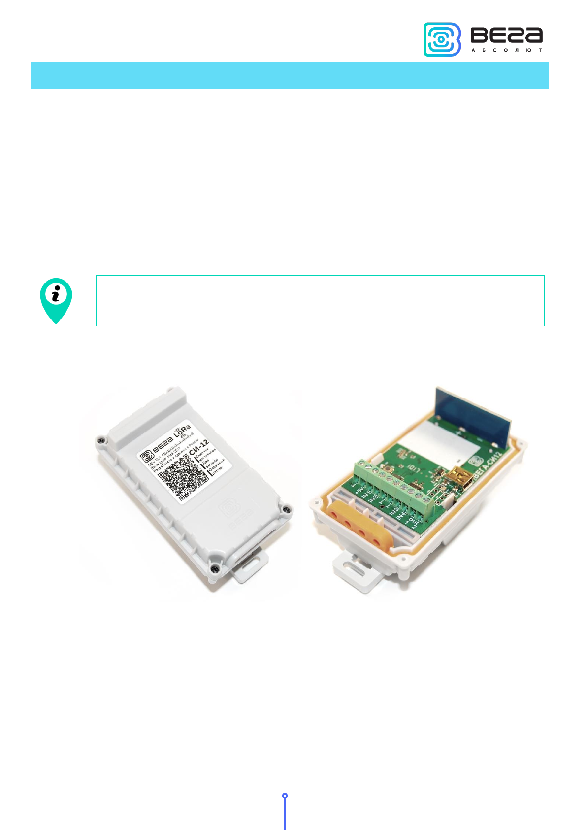
Vega SI-12 pulse counter is designed for counting of pulses incoming to 4 independent
inputs, further accumulating and transmitting of this information via the LoRaWAN protocol to
the gateway through wireless communication within 860-1000 MHz frequency band.
In addition, Vega SI-12 can be used as a security device - all inputs can be configured as
security inputs.
The counter has two open-collector digital outputs and can be used as a control device.
The pulse counter can be used for any utilities’ meters and industrial equipment with
pulse output of herkon type or open-drain type.
De-bouncing logics with 5 msec time constant is integrated in the pulse counter. The
pulse counting is carried out for frequencies up to 200 Hz.
The counter is powered by a 3400 mAh built-in battery with service life up to 10 years,
provided data transmitted once a day. The counter can be powered by the 5V external power
supply.
The counter is configured via USB with special software.
The label on the board contains the information for registering of the device in the
LoRaWAN network:
DevEUI,
DevAddr,
Revision 09 – 04 May 2018
5
Page 6
Revision 09 – 04 May 2018
The pulse counter uses port 2 for data receiving and sending
NwkSKey,
AppSKey,
AppEUI,
AppKey.
Moreover this information is repeated in the label-sticker on the housing cover in the
form of a QR code.
VEGA SI-12/User Manual
6
Page 7

Main
Double-contact digital inputs
up to 4
Maximum input frequency
200 Hz
Security inputs
up to 4
Open-drain outputs
2
USB-port
yes
Operating temperatures
-40…+85 °С
Built-in temperature sensor
yes
LoRaWAN
LoRaWAN class
A or C depending on presence of
the external power supply
Quantity of LoRaWAN channels
16
Frequency band
EU-868, RU-868, custom
Activation type
ABP or OTAA
Communication period
1, 6, 12 or 24 hours
Type of the LoRaWAN antenna
internal
Sensitivity
-138 dBm
Radio coverage in restrained urban conditions
up to 5 km
Radio coverage within line of sight
up to 15 km
Power output
up to 100 mW (configurable)
Power
External power supply
5 V
Built-in battery
3400 mAh
Wireless operation with battery
up to 10 years
Case
Housing dimensions
95 х 50 х 45 mm
Ingress protection rating
IP65
Mounting
Clamp fastening to the support,
DIN-rail, wall-mounting
VEGA SI-12/User Manual
2 SPECIFICATION
VEGA SI-12 pulse counter can be either of A class or C class (LoRaWAN classification)
and has the following features:
o Automatic change from A class to C class when powered from an external power supply
o ADR support (Adaptive Data Rate)
o Sending of confirmed packets (configurable)
o Simultaneous readings from 4 independent inputs
o Two operating modes: "Active" and "Storage"
o Inputs switching to the “Security” mode for connection of leakage, safety and other
external sensors
Revision 09 – 04 May 2018
7
Page 8
Revision 09 – 04 May 2018
o Time referencing of current and archival readings by internal clock
o Communication in case of security inputs actuation
o Temperature measurement
o Charge measuring of the built-in battery (%)
VEGA SI-12/User Manual
8
Page 9
Contact
Designation
Power -
+5V
Power +
IN1, IN2, IN3, IN4
Pulse inputs
,
Signal ground
out 1
out 2
Open-collector outputs 1 and 2
VEGA SI-12/User Manual
3 OPERATION
CONTACTS
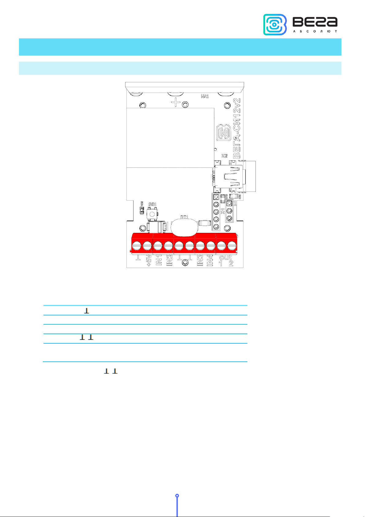
The pulse counter has 10 contacts, see table below (in order from left to right):
Ground contacts ( , ) are used for connection of pulse inputs IN1, IN2, IN3 and IN4.
The counter pulse inputs are used to connect circuits with the following types of NO
contacts:
- reed switch (Herkon);
- mechanical pushbutton;
- open-collector output.
Revision 09 – 04 May 2018
9
Page 10
Revision 09 – 04 May 2018
Equipment with NAMUR pulse output is not supported
VEGA SI-12/User Manual
Any input can be configured for work in the "Security" mode with “Vega LoRaWAN
Configurator” software when connected to the counter via USB. In this case, the device does
not count pulses at the "Security" input, but only monitors its closure. Should the "Security"
input close, the device is activated and sends an alarm message to the network.
10
Page 11
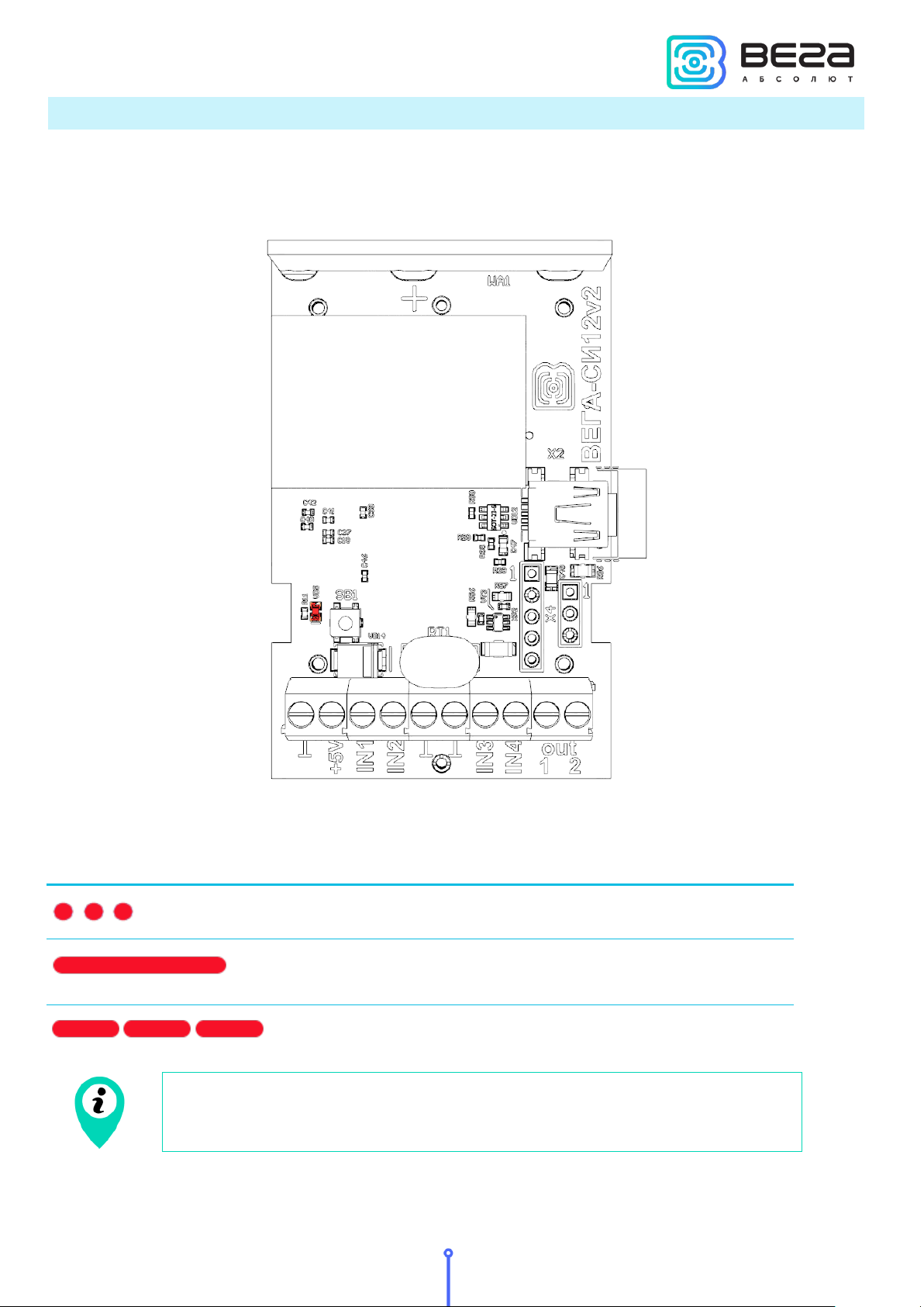
LED signal
Meaning
Series of short flashings
Linking to the network
One long flashing
The device connected to the
network and is in active mode
Three long flashings
The device switched to the
«Storage» mode
In case the device fails to connect the network, the device
automatically switches to the "Storage" mode
VEGA SI-12/User Manual
INDICATION
There is one red LED in the board next to the start button. The indication is only used
when the device is activated in the LoRaWAN network and when the operating modes are
changed.
Revision 09 – 04 May 2018
11
Page 12
Revision 09 – 04 May 2018
VEGA SI-12/User Manual
INITIAL STARTUP
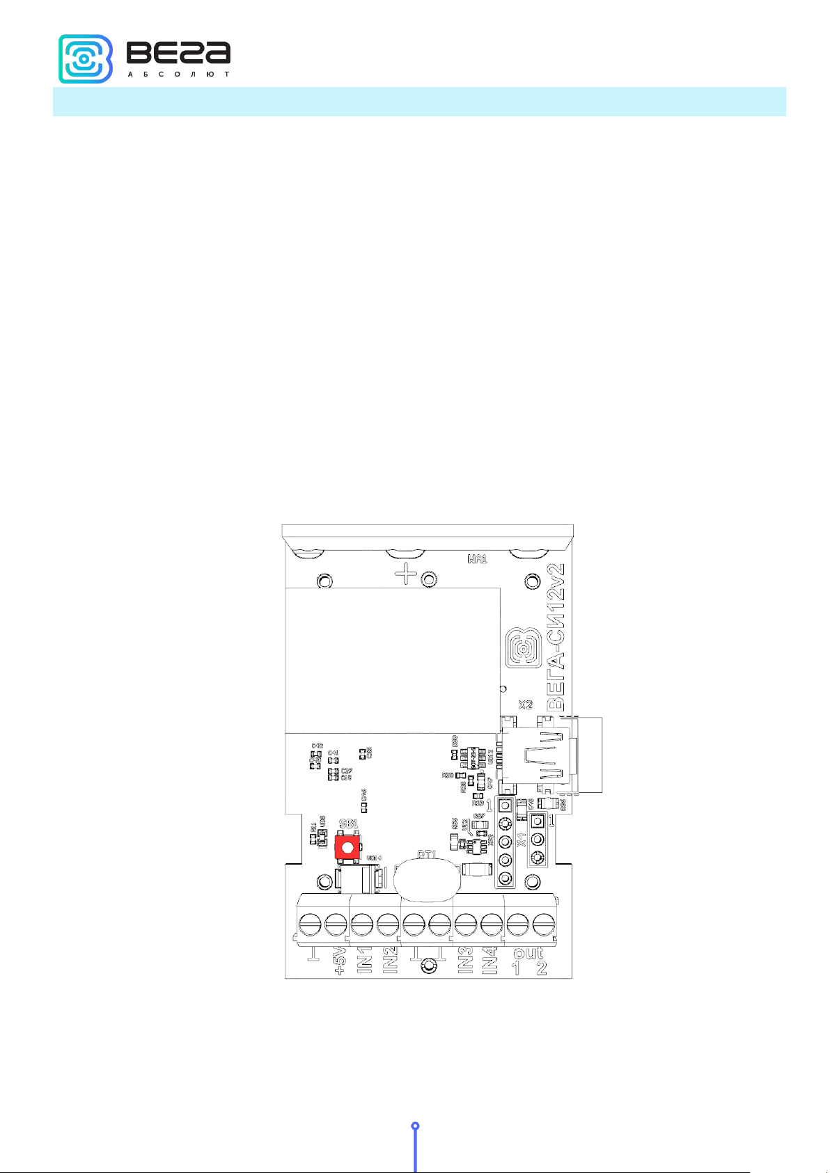
Vega SI-12 pulse counter is constantly on, but can operate in a special "Storage" mode,
designed for storage and transportation. The device does not regularly transmit data to the
network in this mode. Before use, switch the counter from the «Storage» mode.
Vega SI-12 supports two activation methods in the LoRaWAN network - ABP and OTAA.
Select one of the methods using “Vega LoRaWAN Configurator” application (See chapter
“Alignment”).
1. ABP. After pressing the start button, the device immediately starts working in the
"Active" mode.
2. OTAA. After pressing the start button, the device makes three attempts to connect to
the network within the set frequency band. After the activation in the LoRaWAN network is
confirmed, the device sends a signal (LED flashing for 3 seconds) and switches to the "Active"
mode. If all attempts fail, the counter switches to the «Storage» mode.
Hold the start button pressed (min. 5 seconds) to switch the device from the "Active"
mode back to the "Storage" mode.
12
Page 13
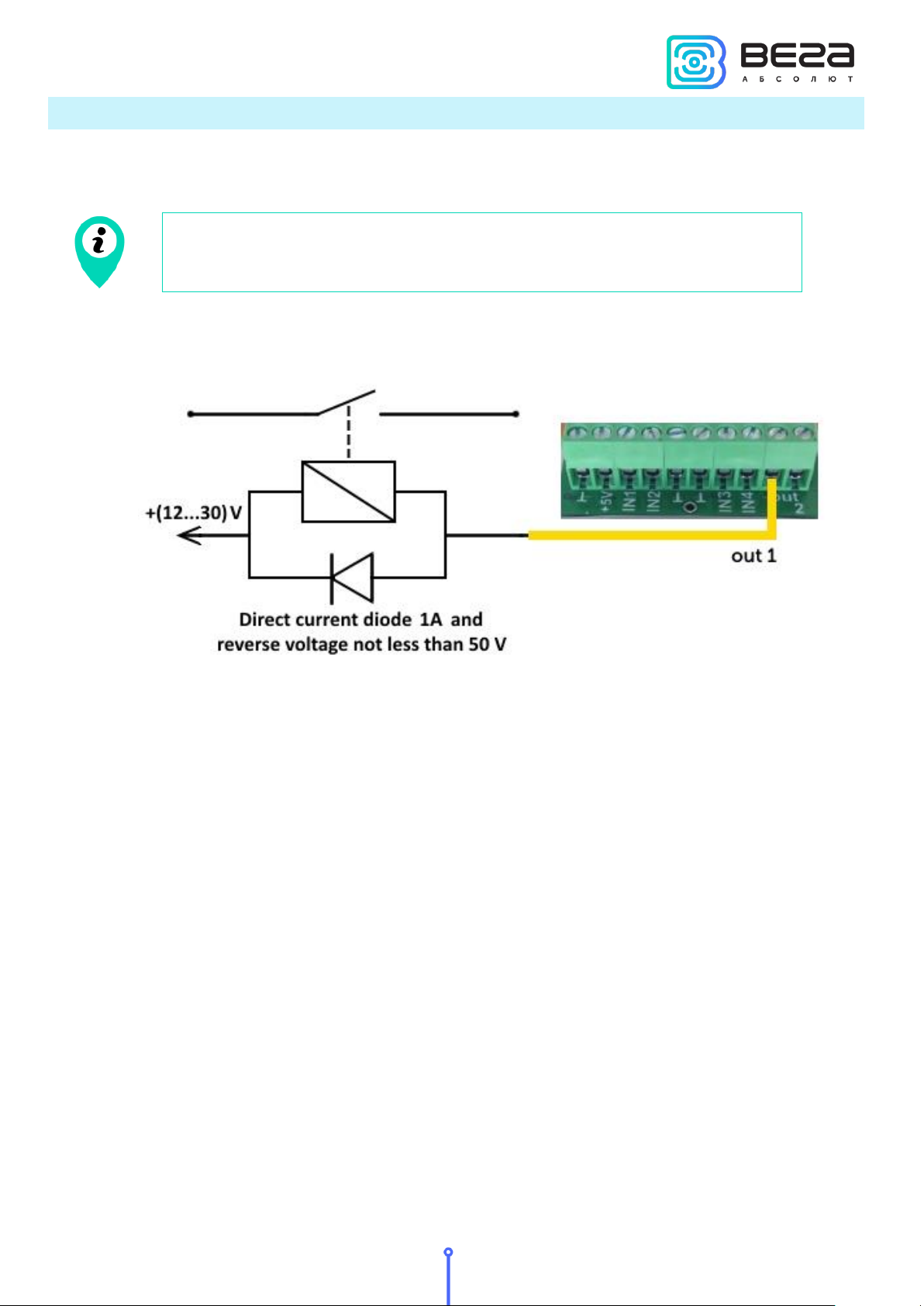
Permissible load for each digital output is 2 A
VEGA SI-12/User Manual
EXTERNAL DEVICES CONNECTION
The actuators are connected to the counter via outputs out 1 и out 2, which are of the
type "Open-drain".
To increase the load on the device outputs, it is necessary to use an external relay. The
relay connection scheme is shown below.
Revision 09 – 04 May 2018
13
Page 14
Revision 09 – 04 May 2018
CONNECTING VIA USB
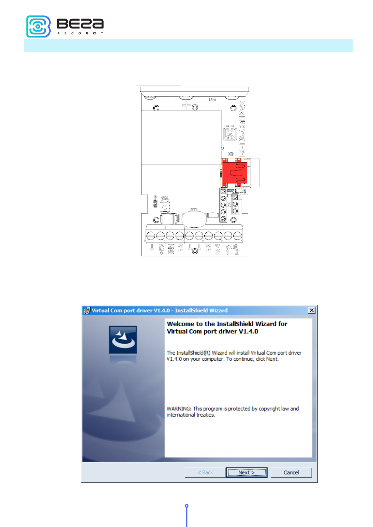
The pulse counter can be adjusted with the "Vega LoRaWAN Configurator" application
(See part 4).
VEGA SI-12/User Manual
Before connecting the device to the computer for the first time, you must install the
driver for the COM port stsw-stm32102, which can be downloaded from iotvega.com. After
running the executable file VCP_V1.4.0_Setup.exe, the installer window will appear:
14
Page 15
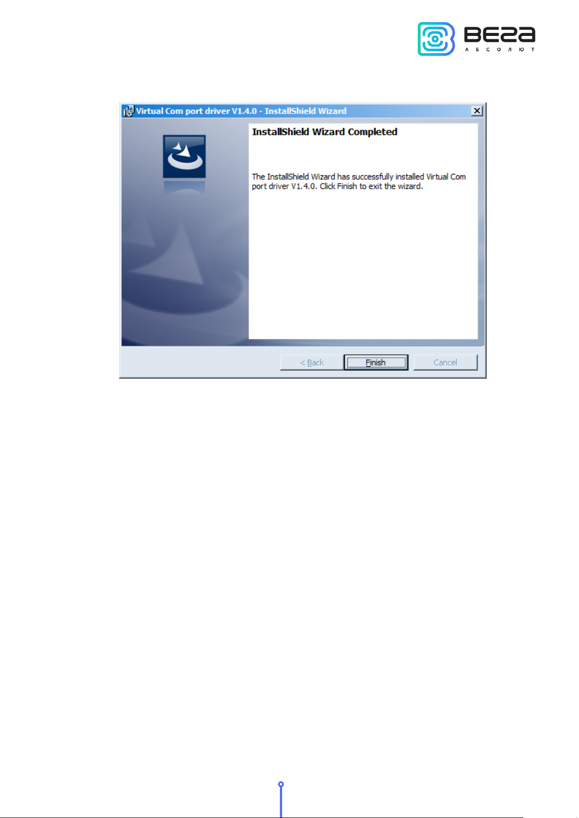
VEGA SI-12/User Manual
In this window, you need to click Next, then Install, and then the installation will begin.
When the installation is completed successfully, the following screen appears:
After pressing Finish the driver is ready for operation, - it is possible to connect the pulse
counter via USB.
Revision 09 – 04 May 2018
15
Page 16
Revision 09 – 04 May 2018
VEGA SI-12/User Manual
4 VEGA LORAWAN CONFIGURATOR
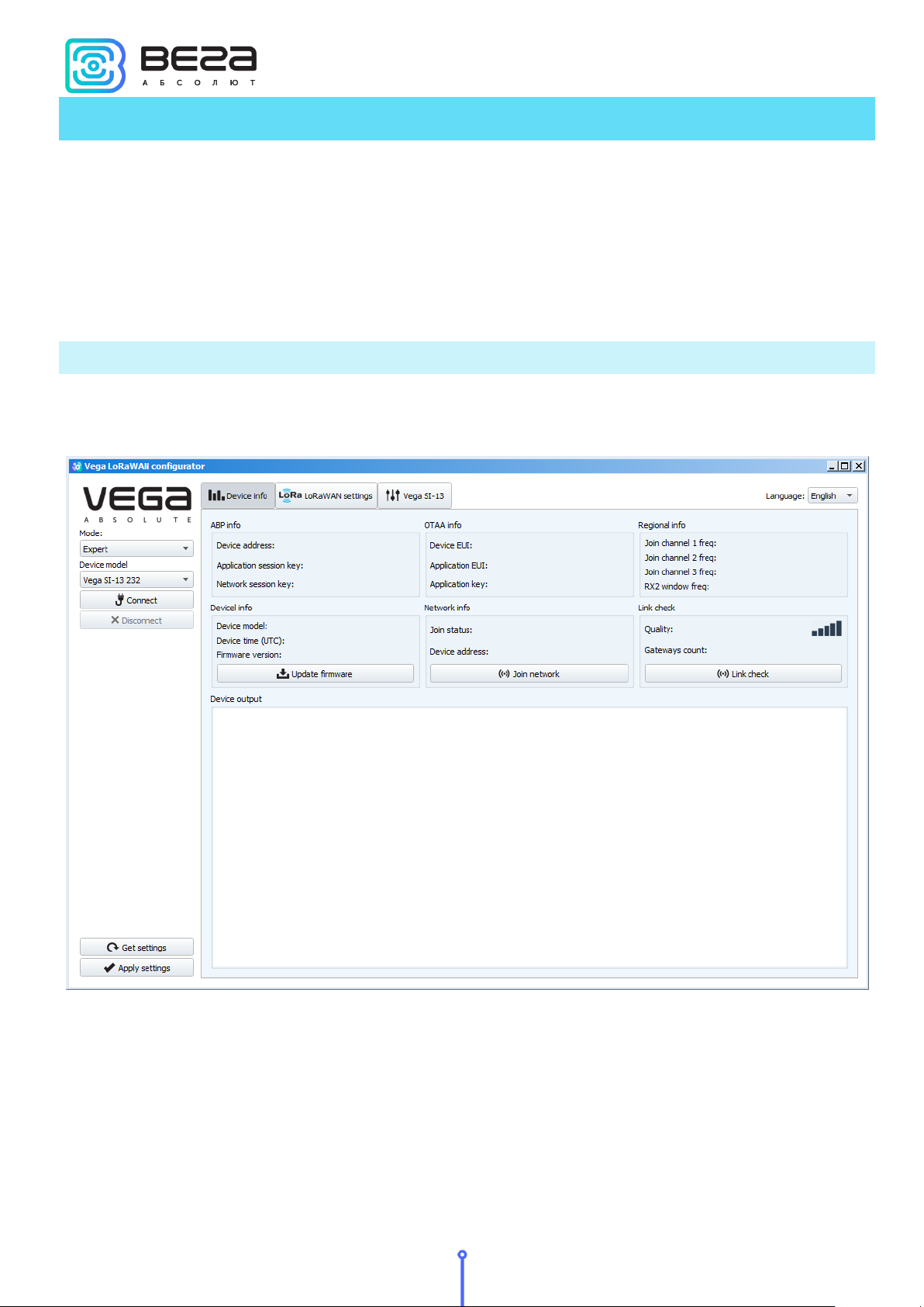
The "Vega LoRaWAN Configurator" application (hereinafter referred to as the
configurator) is intended for setting up the device via USB.
The configurator has two modes of operation - "Simple" and "Expert". In the "Simple"
mode, only basic settings are available. In the "Expert" mode, the basic settings, advanced
settings and the ability to check the coverage area of the signal from the gateways are
available. Next, the work of the application is considered in the “Expert” mode.
INTERFACE OF THE APPLICATION
The "Vega LoRaWAN Configurator" application does not require the special installation.
When the executable file is launched, the window for working with the application appears.
The menu on the left allows you to switch between the “Simple” and “Expert” modes,
select the device model, connect to the device or disconnect from it, get and apply settings.
The application window contains three tabs – Device info, LoRaWAN settings and device
settings.
The language selection menu is in the upper right corner.
16
Page 17
VEGA SI-12/User Manual
CONNECTION TO THE DEVICE
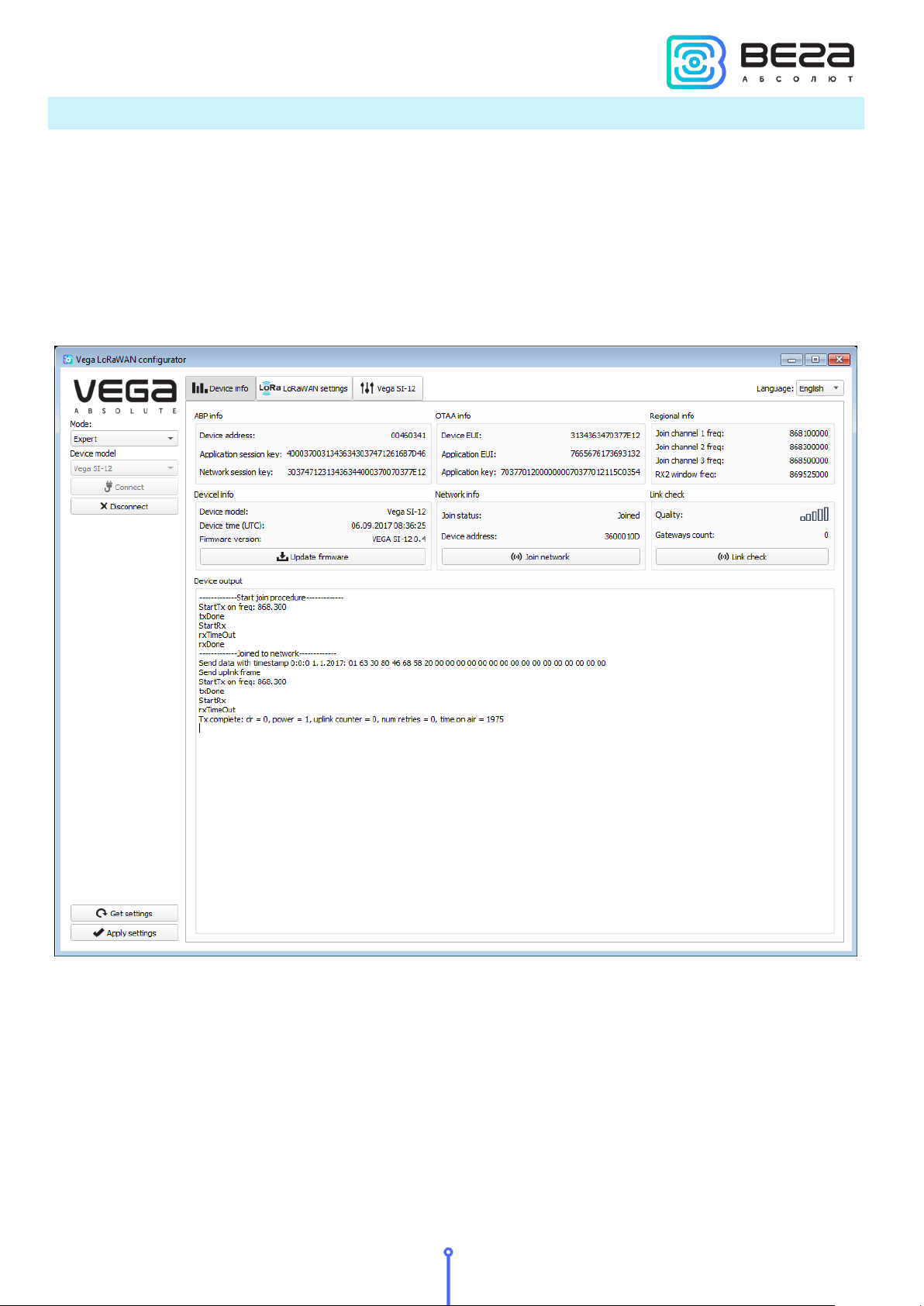
For the connection to the device, perform the following steps:
1. Connect the USB cable to the device.
2. Start the "Vega LoRaWAN Configurator" application.
3. Click the "Connect" button in the menu on the left.
The application automatically recognizes the type of device, and the device selection
menu becomes inactive.
To read the settings from the device, you need to click the "Get settings" button, until
this point the application will display the default settings or from the last connected device.
After making the necessary changes to the settings, you should click the "Apply settings"
button and only then disconnect from the device with the "Disconnect" button.
Revision 09 – 04 May 2018
17
Page 18
Revision 09 – 04 May 2018
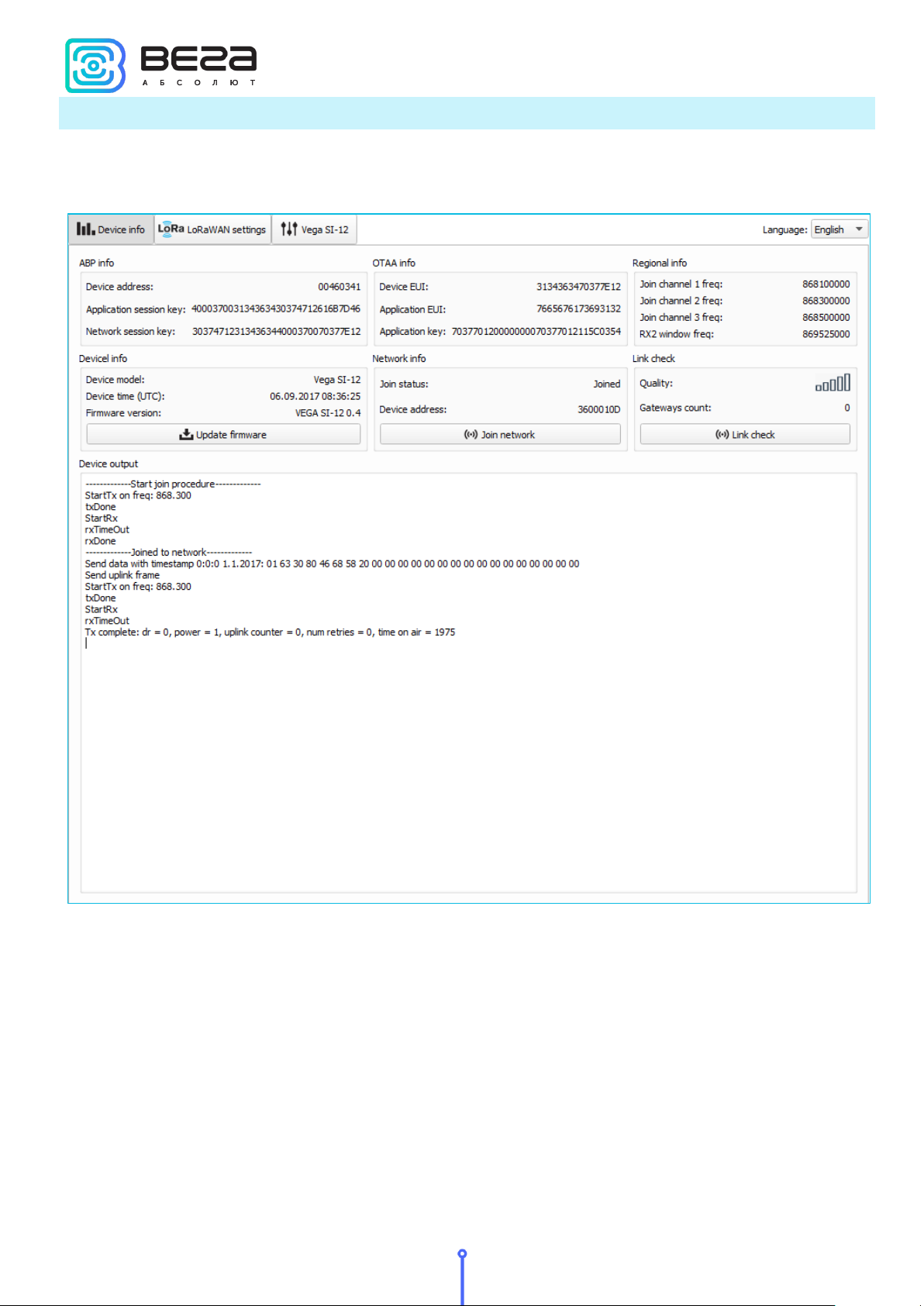
“DEVICE INFO” TAB
The "Device info" tab displays information about the device, its current status, and also
the data needed to register the device in the LoRaWAN network.
VEGA SI-12/User Manual
ABP info - displays the data necessary to register the device in the LoRaWAN network
with ABP method (Activation By Personalization).
OTAA info - the data required to register the device in the LoRaWAN network with OTAA
method (Over The Air Activation) is displayed.
Regional info (not displayed in the "Simple" mode) - shows the frequencies of the JOIN
channels and the second receiving window. These frequencies can be changed in the
"LoRaWAN Settings" tab when selecting a frequency plan.
Device info - the configurator reads information about the device model, its firmware
and automatically corrects the device's time when connected to it.
18
Page 19
VEGA SI-12/User Manual
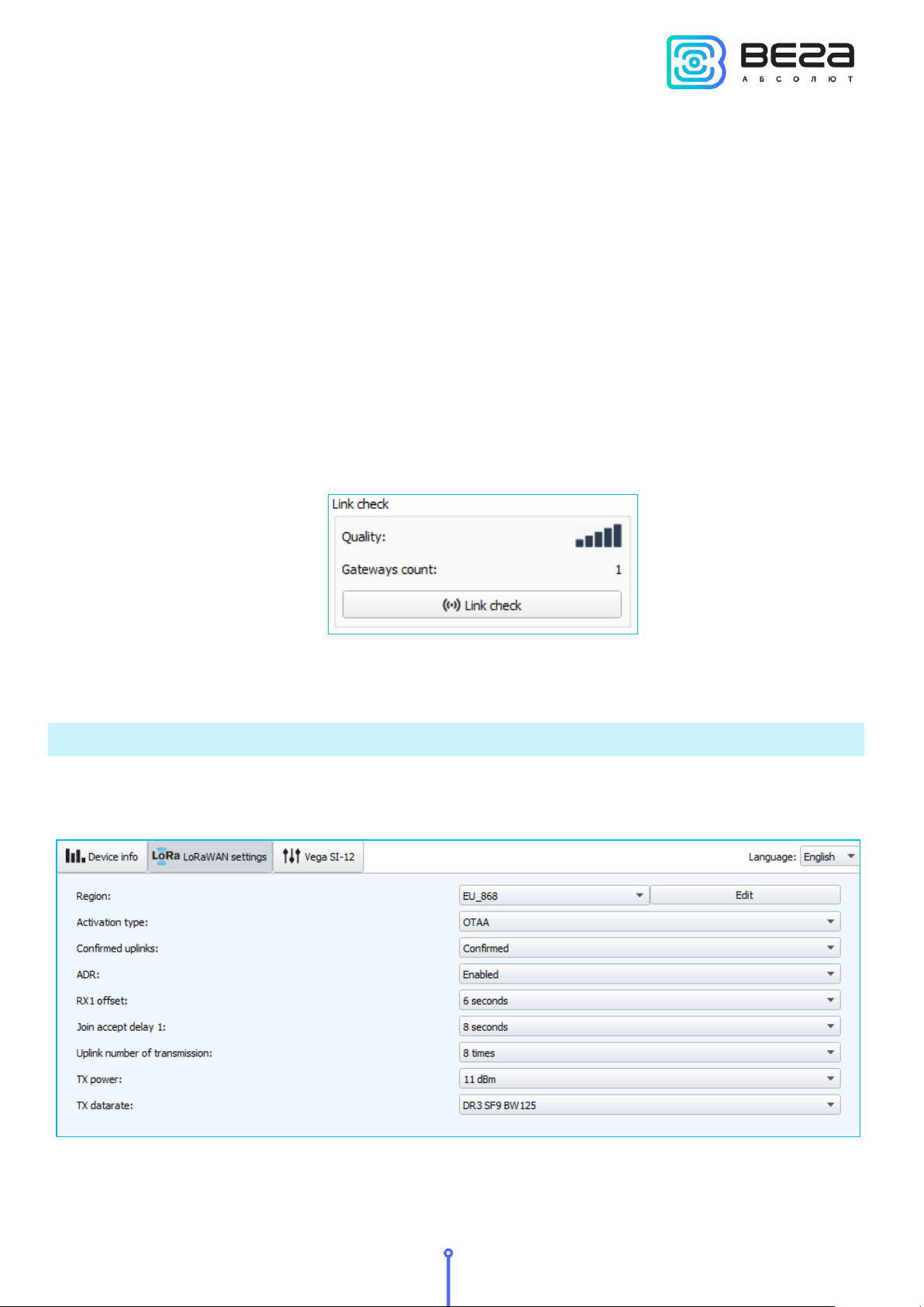
Update firmware - allows you to select the firmware file from your computer's hard
drive and load it into the device. The device will automatically disconnect from the
configurator when the download is complete. The current version of the device firmware can
be downloaded from iotvega.com.
Network info - shows whether the device is connected to the LoRaWAN network and its
network address.
Join network button - launch the LoRaWAN network connection procedure with the
previously selected ABP or OTAA method. If the device is already connected to the network,
reconnection procedure will occurs.
Link check (not displayed in the "Simple" mode) - when pressed, the device sends a
special signal to the LoRaWAN network, in response to which the network informs it of the
number of gateways that received this signal and the signal quality. This button only works
when the device is connected to the network.
Device output (not displayed in the "Simple" mode) - monitoring the device status, all
events in real time are displayed.
“LORAWAN SETTINGS” TAB
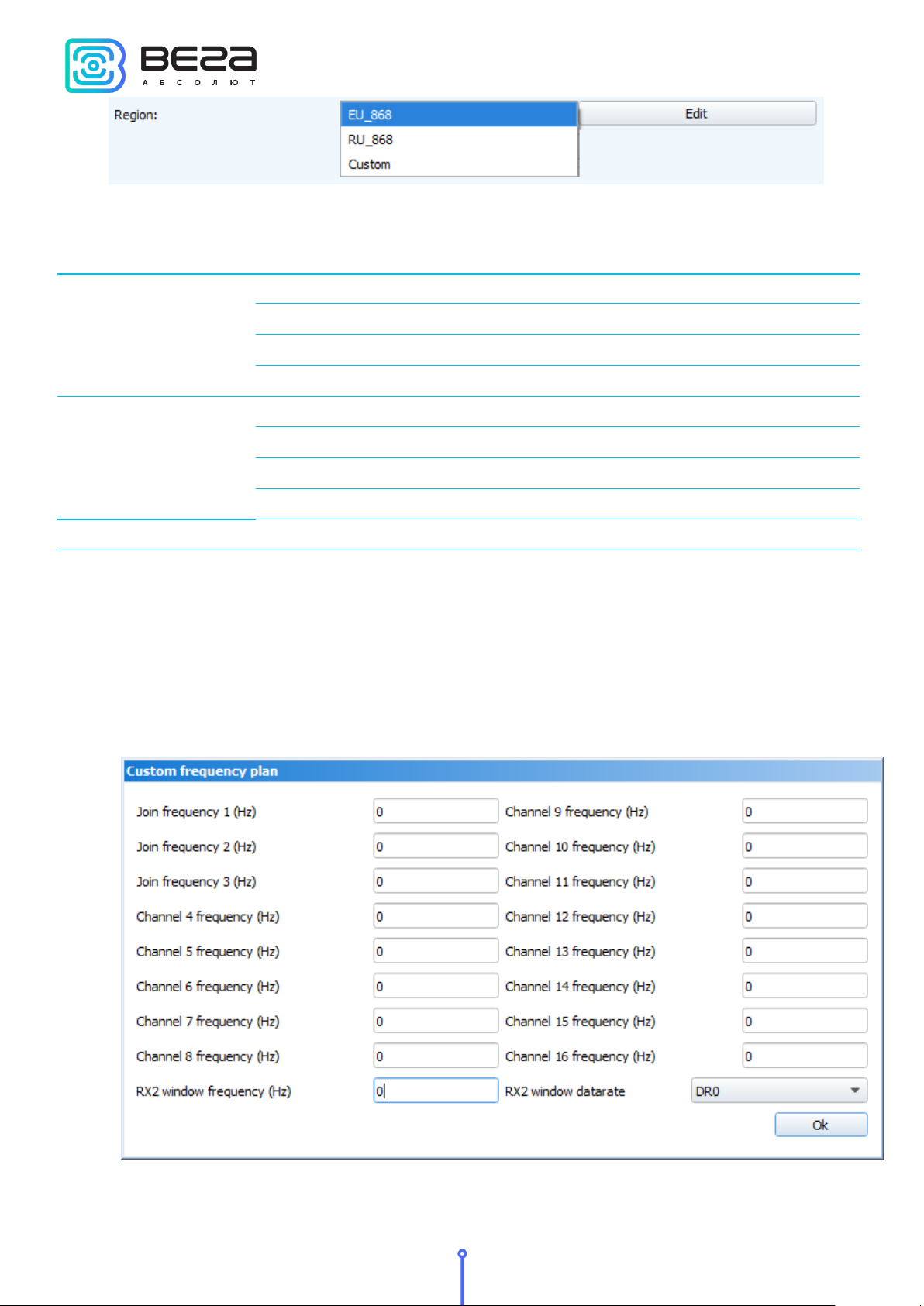
The "LoRaWAN Settings" tab allows you to configure various parameters of the LoRa
network.
Region - allows you to select RU-868, EU-868 or specify a custom frequency band.
Revision 09 – 04 May 2018
19
Page 20
Revision 09 – 04 May 2018
Frequency band
Channel
Frequency
Modulation
EU-868
1
868.1
MultiSF 125 kHz
2 868.3
MultiSF 125 kHz
3
868.5
MultiSF 125 kHz
RX2
869.525
SF12 125 kHz
RU-868
1 864.5
MultiSF 125 kHz
2
864.7
MultiSF 125 kHz
3 864.9
MultiSF 125 kHz
RX2
869.05
SF12 125 kHz
Custom
Set with «Vega LoRaWAN Configurator» application
The pulse counter supports the following frequency bands:
VEGA SI-12/User Manual
In the EU_868 and RU_868 frequency bands, only 3 channels are active by default. The
device sends requests for connection to the network on this "join" channels. The remaining
channels that the device should use can be transferred by the LoRaWAN network server during
the device activation procedure (only OTAA).
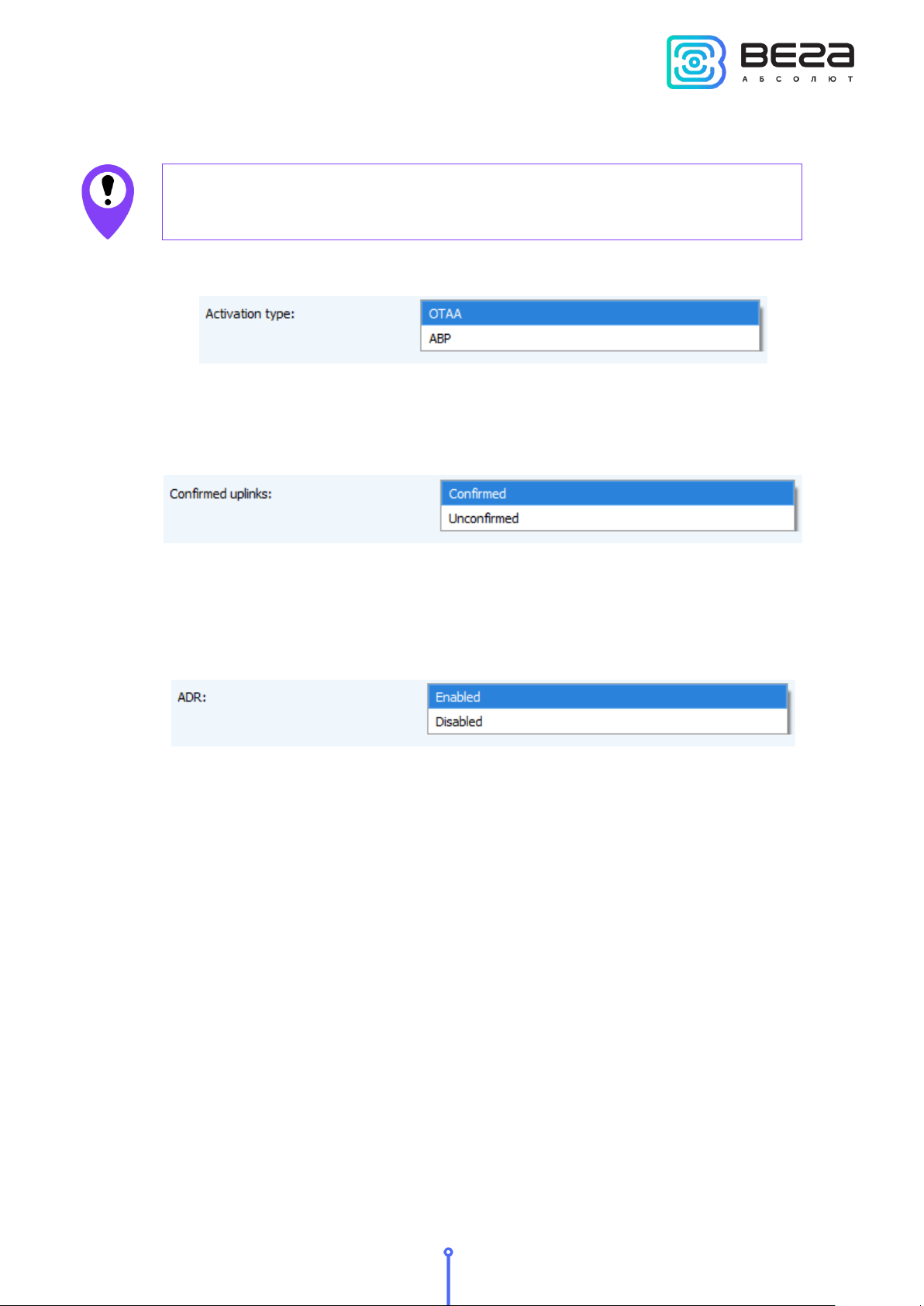
If you select "Custom" in the "Region" field, you must manually specify the frequencies
that the device will use. To do this, click the "Edit" button, the channel frequency editing
window will appear:
20
Page 21
The first three channels and the second receiving window
parameters are mandatory. Without these parameters the custom
frequency band will be considered empty
VEGA SI-12/User Manual
This frequency band allows you to set up to 16 channels, as well as the frequency and
speed of the second receiving window.
Activation type – selecting ABP or OTAA device activation method.
Confirmed uplinks – when you choose "confirmed", the device will retry sending the
packet until it receives the server confirmation, or until the "Uplink number of transmission" is
over (see below).
ADR – this option activates the Adaptive Data Rate algorithm for automatic control of
the data transfer rate from the LoRaWAN network side. The higher the quality of the signal
received by the network, the higher the speed will be installed on the device. This option is
recommended only on permanently installed devices.
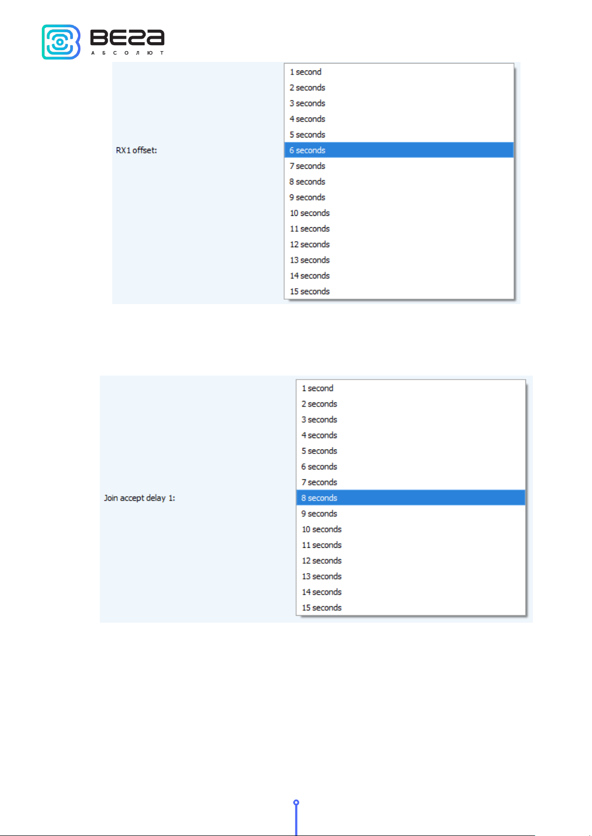
RX1 offset (not displayed in the "Simple" mode) – specifies the time between end of
packet transmission and first receiving window opening. The second receiving window always
opens after 1 second after the first.
Revision 09 – 04 May 2018
21
Page 22
Revision 09 – 04 May 2018
VEGA SI-12/User Manual
Join accept delay 1 (not displayed in the "Simple" mode) – sets the time that the device
will open the first receiving window to receive confirmation for the join request from the
LoRaWAN network. The second window always opens after 1 second after the first.
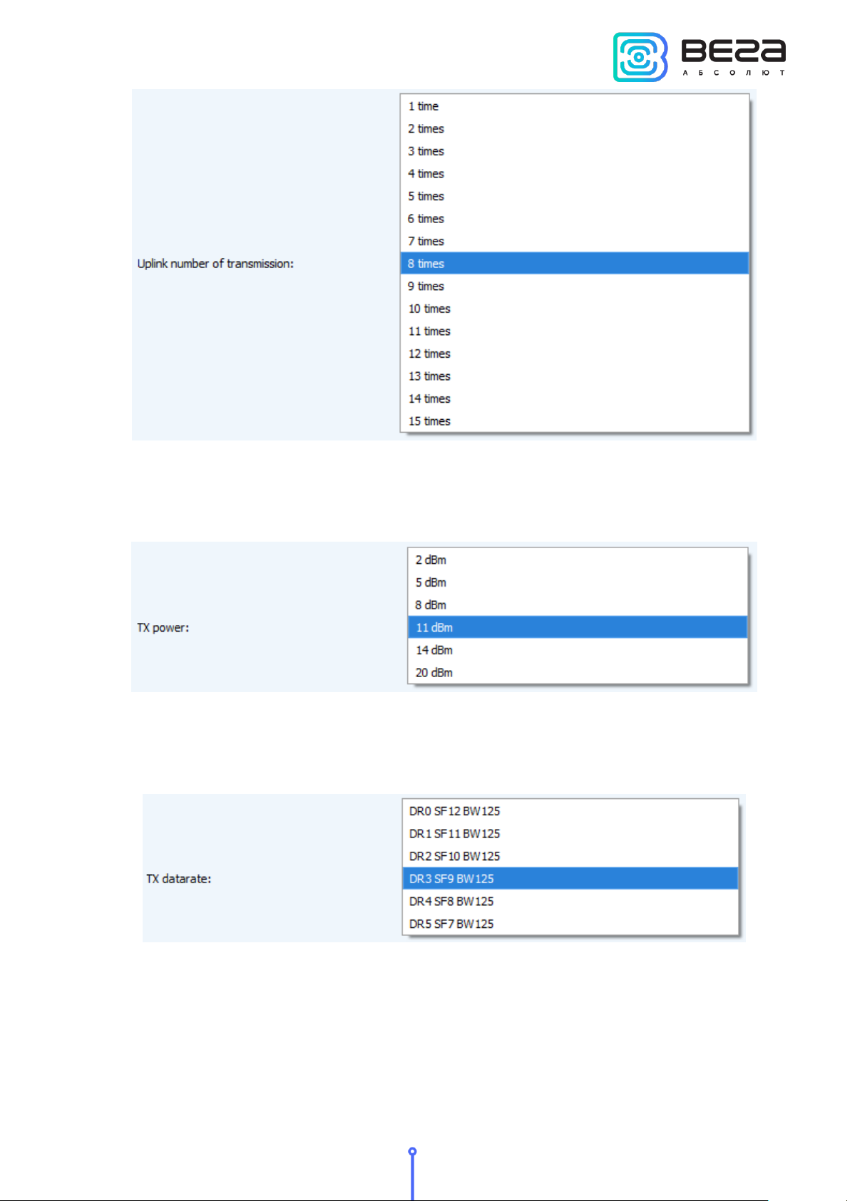
Uplink number of transmission (not displayed in the "Simple" mode) – if the "Confirmed
uplinks" function is disabled, the device will simply send each packet as many times as specified
in this option. If "Confirmed uplinks" is enabled, the device will send packets until it receives a
confirmation or until it sends as many packets as specified in this option.
22
Page 23
VEGA SI-12/User Manual
TX power (not displayed in the "Simple" mode) – the device RF transmitter power is
adjusted to this value when sending packets to the LoRaWAN network. This option can be
changed by the network server.
TX datarate (not displayed in the "Simple" mode) – the device transmission datarate at
which it will transfer packets to the LoRaWAN network. This speed can be changed by the
network server if the ADR algorithm is enabled.
Revision 09 – 04 May 2018
23
Page 24
Revision 09 – 04 May 2018
“VEGA SI-12” TAB
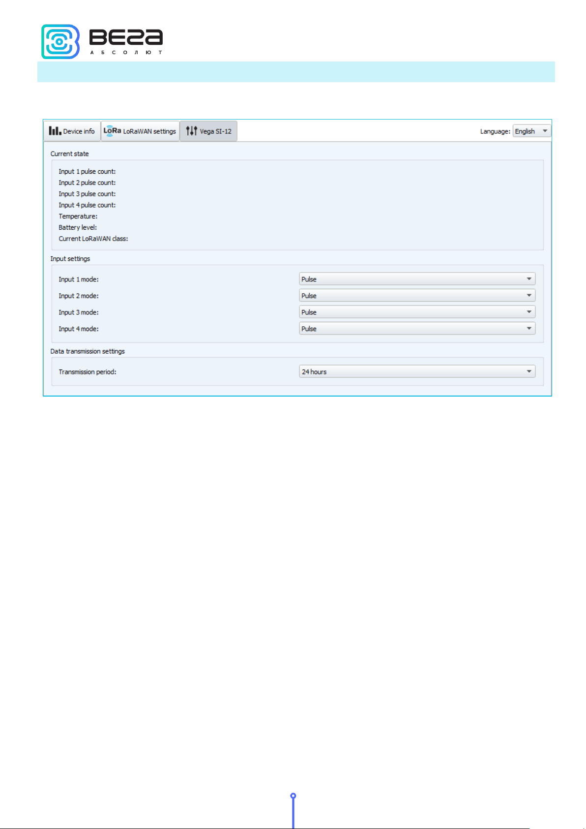
The “Vega SI-12” tab contains the settings of the connected device.
VEGA SI-12/User Manual
Current state – displays the current parameters of the device - the number of counted
pulses at the inputs, the temperature, the battery level and the current LoRaWAN class.
Input settings – allow you to change the operation of the pulse inputs from the
counting of pulses to the security mode and back. When transferring the input to the security
mode, the device will send an alarm packet to the network (See part 5, packet 2) whenever this
input is closed. The maximum possible frequency of sending alarm packets is one per 10
seconds.
Data transmission settings – the transmission period which the packet with the current
readings is transmit (See part 5, packet 1).
24
Page 25
Size in bytes
Field description
1 byte
Packet type, this packet = 1
1 byte
Battery charge, %
1 byte
Values of basic settings (bit field)
4 bytes
Reading time for values in this packet (unixtime UTC)
1 byte
Temperature, °С
4 bytes
Input 1 reading (depending on the type – number of pulses or
status: 0 – open, 1 - closed)
4 bytes
Input 2 reading (depending on the type – number of pulses or
status: 0 – open, 1 - closed)
4 bytes
Input 3 reading (depending on the type – number of pulses or
status: 0 – open, 1 - closed)
4 bytes
Input 4 reading (depending on the type – number of pulses or
status: 0 – open, 1 - closed)
Size in bytes
Field description
0 bit
Activation type: 0 - OTAA, 1 – ABP
1 bit
Query for packet confirmation: 0 – off, 1 – on
2,3 bits
Communication period:
|2==0|3==0| - 1 hour
|2==1 |3==0| - 6 hours
|2==0|3==1 | - 12 hours
|2==1 |3==1 | - 24 hours
4 bits
First input type: 0 – pulse, 1 - security
5 bits
Second input type: 0 – pulse, 1 - security
6 bits
Third input type: 0 – pulse, 1 - security
7 bits
Fourth input type: 0 – pulse, 1 - security
VEGA SI-12/User Manual
5 COMMUNICATION PROTOCOL
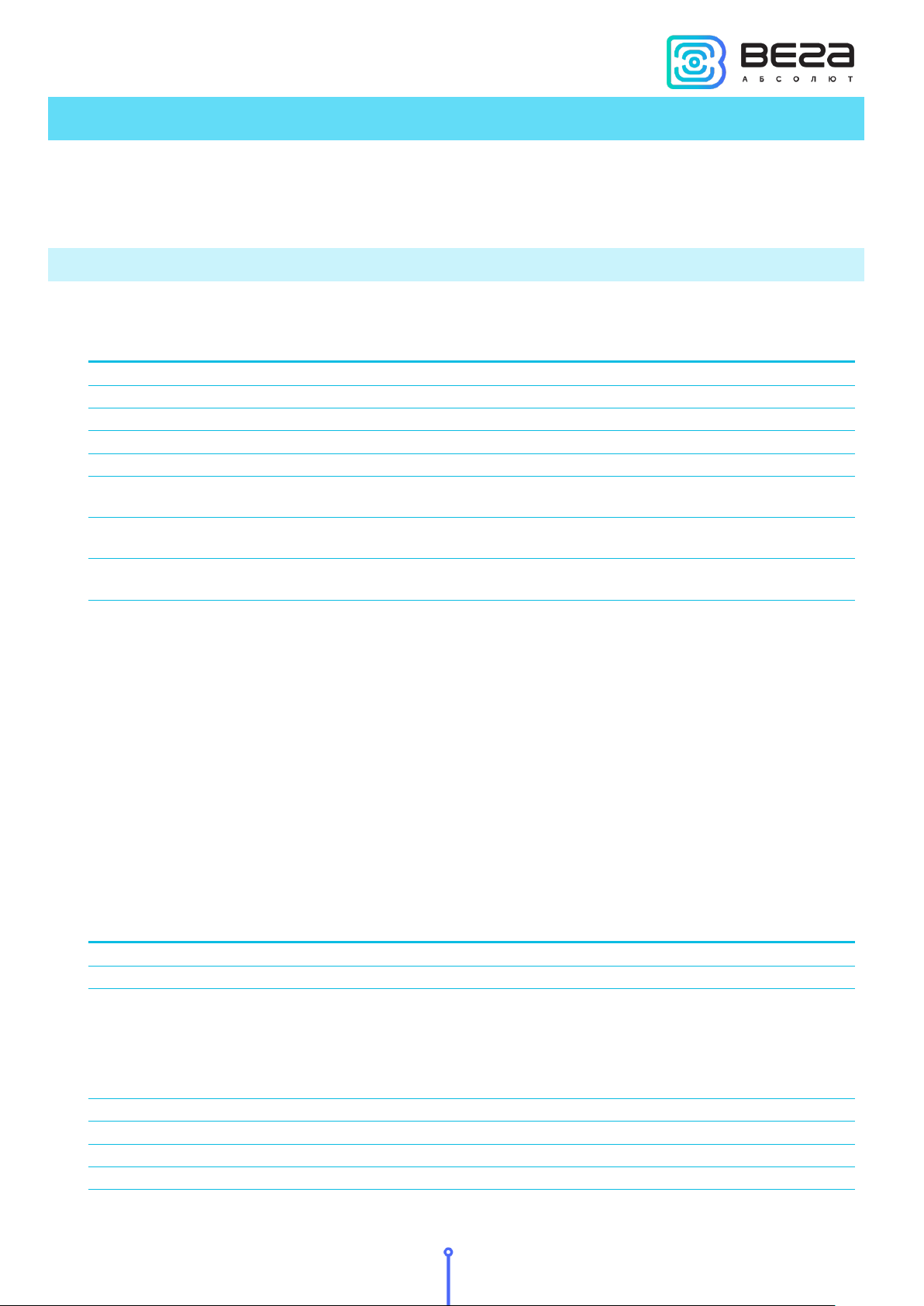
This part describes the SI-12 data exchange protocol with LoRaWAN network. SI-12 uses
the LoRaWAN port 2 for uplink and downlink messages. In fields consisting of several bytes, the
little endian byte order is used.
VEGA SI-12 PULSE COUNTER TRANSMITS THE FOLLOWING TYPES OF PACKETS:
1. Packet with current readings, sent regularly
The counter has internal clock and calendar; time and date is factory set. When sending a
packet with the current readings, the device uses the data taken at the nearest time, which is
multiple to the interval, set by the switches:
• 1 hour period: the readings of the beginning of the current hour are sent;
• 6 hours period: 00:00, 06:00, 12:00, 18:00 readings are sent;
• 12 hours period: 00:00, 12:00 readings are sent;
• 24 hours period: the readings of 00:00 of the current day are sent.
"Values of basic settings" bit field decoding
Revision 09 – 04 May 2018
25
Page 26
Revision 09 – 04 May 2018
Size in bytes
Field description
1 byte
Packet type, this packet = 2
1 byte
Battery charge, %
1 byte
Values of basic settings (bit field)
1 byte
Input No, where the alarm is detected (3 or 4)
4 bytes
Input 1 reading (depending on the type – number of pulses or
status: 0 – open, 1 - closed)
4 bytes
Input 2 reading (depending on the type – number of pulses or
status: 0 – open, 1 - closed)
4 bytes
Input 3 reading (depending on the type – number of pulses or
status: 0 – open, 1 - closed)
4 bytes
Input 4 reading (depending on the type – number of pulses or
status: 0 – open, 1 - closed)
Size in bytes
Field description
1 byte
Packet type, this packet = 3
1 byte
Battery charge, %
1 byte
Values of basic settings (bit field)
1 byte
Input no. for which log is sent (1 - 4)
1 byte
Number of records in the log
1 byte
Log type (0 – Hourly, 1 – daily, 2 – monthly, 3 - temperature)
4 bytes
Reading time of the latest metering in this packet (unixtime)
4 bytes
Log recording
… … 4 bytes
Log recording
Size in bytes
Field description
1 byte
Packet type, this packet = 4
1 byte
Battery charge, %
1 byte
Values of basic settings (bit field)
1 byte
External power state (0 – off, 1 - on)
VEGA SI-12/User Manual
2. «Alarm» packet sent in case of security input closure
When sending alarm packet, the device uses the data taken at moment of communication
start
3. Packet with readings log, sent on request
The LoRa data transfer technology limits the maximum packet size, depending on the
speed of packet transmission. If the readings log cannot be sent in one packet, it is divided into
several packets, which are sent in series until the entire requested log is sent. Records in the log
packet are arranged from the newest to the oldest.
4. External power information packet, sent in case of change external power status
5. Output state information packet, sent in case of change output state
26
Page 27
Размер в байтах
Описание поля
1 байт
Packet type, this packet = 5
1 байт
Battery charge, %
1 байт
Values of basic settings (bit field)
1 байт
Output number (1-2)
1 байт
New output state (0 – off, 1 - on)
Size in bytes
Field description
1 byte
Packet type, this packet = 1
4 bytes
Current time (unixtime UTC)
Size in bytes
Field description
1 byte
Packet type, this packet = 2
1 byte
Input no. (1 – 4, 5 for temperature)
1 byte
Log type (0 – hourly, 1 – daily, 2 – monthly)
Size in bytes
Field description
1 байт
Packet type, this packet = 3
1 байт
Output no. (1 - 2)
1 байт
Output on time in seconds (1 – 255, 0 - forever).
Size in bytes
Field description
1 байт
Packet type, this packet = 4
1 байт
Output no. (1 - 2)
VEGA SI-12/User Manual
VEGA SI-12 PULSE COUNTER RECEIVES PACKETS OF THE FOLLOWING TYPES:
1. Real-time clock adjustment
When receiving the packet the pulse counter sets its internal clock and calendar in compliance
with the received packet.
2. Query of readings log
3. Output on command
4. Output off command
Revision 09 – 04 May 2018
27
Page 28
Revision 09 – 04 May 2018
VEGA SI-12/User Manual
6 STORAGE AND TRANSPORTATION REQUIREMENTS
Vega SI-12 pulse counter shall be stored in the original packaging in heated room at
temperatures +5°С to +40°С and relative humidity less than 85%.
The counter shall be transported in covered freight compartments of all types at any
distance at temperatures -40°C to +85°C.
28
Page 29
VEGA SI-12/User Manual
7 CONTENT OF THE PACKAGE
The pulse counter is delivered complete with:
Vega SI-12 pulse counter – 1 pce.
Screw – 4 pce.
Factory certificate – 1 pce.
Revision 09 – 04 May 2018
29
Page 30
Revision 09 – 04 May 2018
8 WARRANTY
The warranty period for the device is 5 years from the date of sale or 80,000 packages
sent by the device, whichever comes first.
The manufacturer is obligated to provide repair services or replace the failed device
during the entire warranty period.
The consumer is obliged to comply with the conditions and rules of transportation,
storage and operation specified in this user manual.
Warranty does not apply to:
- devices that sent more than 80,000 packets;
- the device with mechanical, electrical and / or other damages and defects caused by
violation of the transportation, storage and operation requirements;
VEGA SI-12/User Manual
- the device with traces of repair performed not by the manufacturer's service center;
- the device with traces of oxidation or other signs of liquids leaking inside the device.
In the event of a warranty claim, contact the service center:
113/1, Kirova Str., Novosibirsk, 630008, Russia.
Tel.: +7 (383) 206-41-35.
30
Page 31
VEGA SI-12/User Manual
vega-absolute.ru
Operation Manual © Vega-Absolute LLC 2017
Revision 09 – 04 May 2018
31
 Loading...