

Page 1
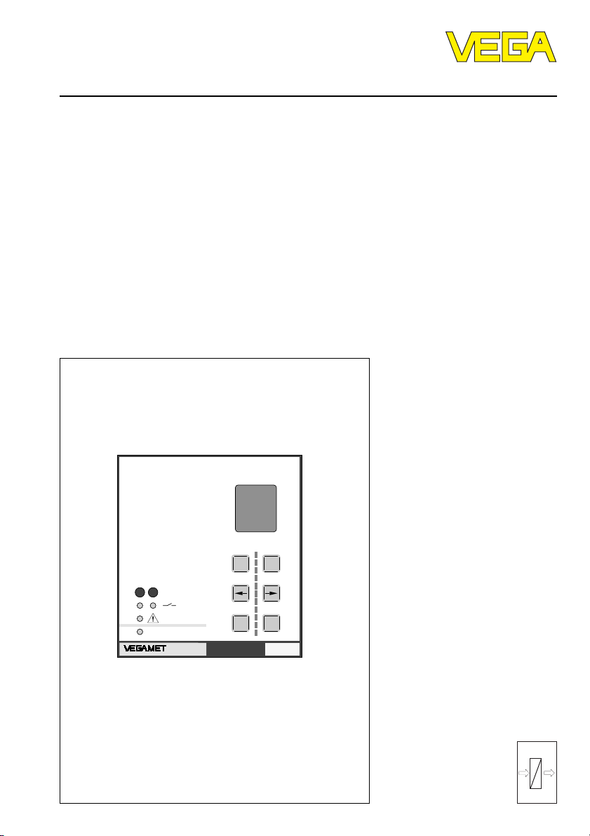
Operating Instructions
VEGAMET 614
Level and Pressure
CONNECT
12
on
614
%
100
+
-
OKESC
Ser.No.
12345678
out
in
Page 2

Contents
1 Product description
1.1 Function and configuration ................................................ 4
1.2 Approvals ........................................................................... 5
1.3 Features............................................................................. 5
1.4 Technical data .................................................................... 6
1.5 Dimensions......................................................................... 9
2 Mounting and installation instructions .............................. 10
3 Electrical connection
3.1 Connection instructions ................................................... 12
3.2 Connection instructions for Ex approved applications . 12
3.3 Wiring plan ........................................................................ 12
4 Adjustment
4.1 Indicating and adjustment elements ............................... 13
4.2 Adjustment system .......................................................... 14
4.3 Adj ustmen t via PC ........................................................... 15
4.4 Configuration and parameter adjustment ....................... 16
4.5 Comparison: reduced menu – extended menu .............. 17
Contents
5Setup.......................................................................................... 18
6 Settings in the "Reduced menu“
6.1 Con figurati on of mea surement loop ............................... 19
6.2 Adj ust men t wi th med ium.................................................. 20
6.3 Adjustment without medium ............................................ 21
6.4 Scaling .............................................................................. 22
6.5 Inte gration ti me ................................................................ 23
6.6 Outputs............................................................................. 24
6.8 Password, language, default, reset, menu mode .......... 25
6.7 Simulation ......................................................................... 25
2 VEGAMET 614
Page 3

Contents
7 Settings in the "Extended menu“
7.1 Config uration o f measur ement loo p ............................... 26
7.2 Configuration of inputs ..................................................... 28
7.3 Configu ration of ou tputs .................................................. 2 9
7.4 Adjustment........................................................................ 30
7.5 Conditioning...................................................................... 31
7.6 Paramet er adjustm ent of outp uts ................................... 32
7.7 Simulation ......................................................................... 37
7.8 Special function: Reset .................................................... 37
7.9 Password, language, menu mode .................................. 38
7.10 Special function: Manual correction ................................ 38
7.11 Li nearisa tion cur ves ........................................................ 39
7.12 Info .................................................................................... 42
7.13 Reset VEGAMET ............................................................. 43
8 Measured quantity and units ................................................ 44
9 Diagnosis
9.1 Maintenance..................................................................... 45
9.2 Simulation ......................................................................... 45
9.3 Fault signal........................................................................ 45
9.4 Repair............................................................................... 45
9.5 Error codes ...................................................................... 46
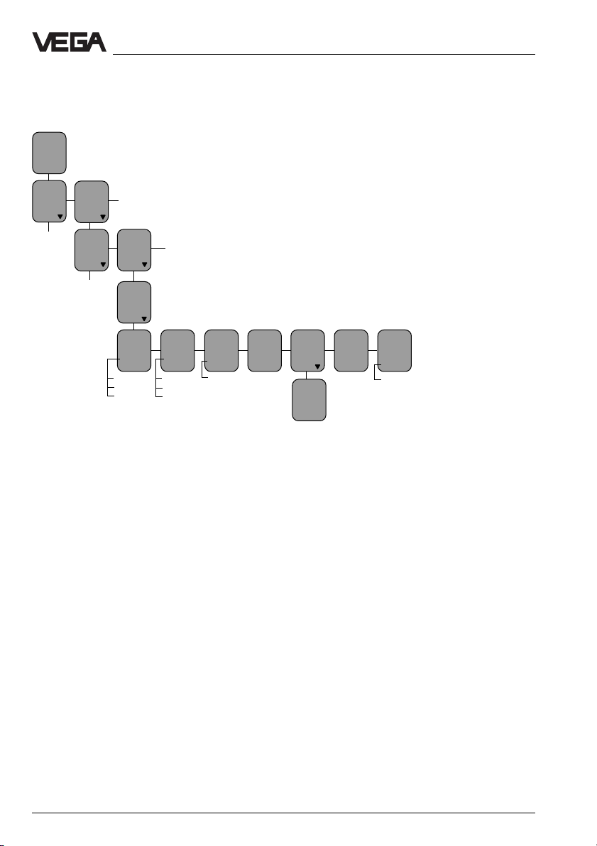
10 Menu schematics
10.1 Menu schematic “reduced menu” .................................. 49
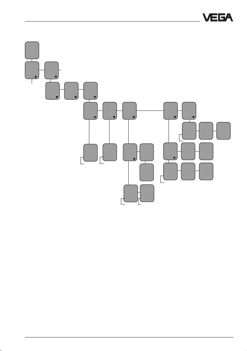
10.2 Menu schematic “extended menu” ................................. 50
Safety informatio n ...................................................................... 56
Note Ex area .............................................................................. 56
VEGAMET 614 3
Page 4
1 Product description
Product description
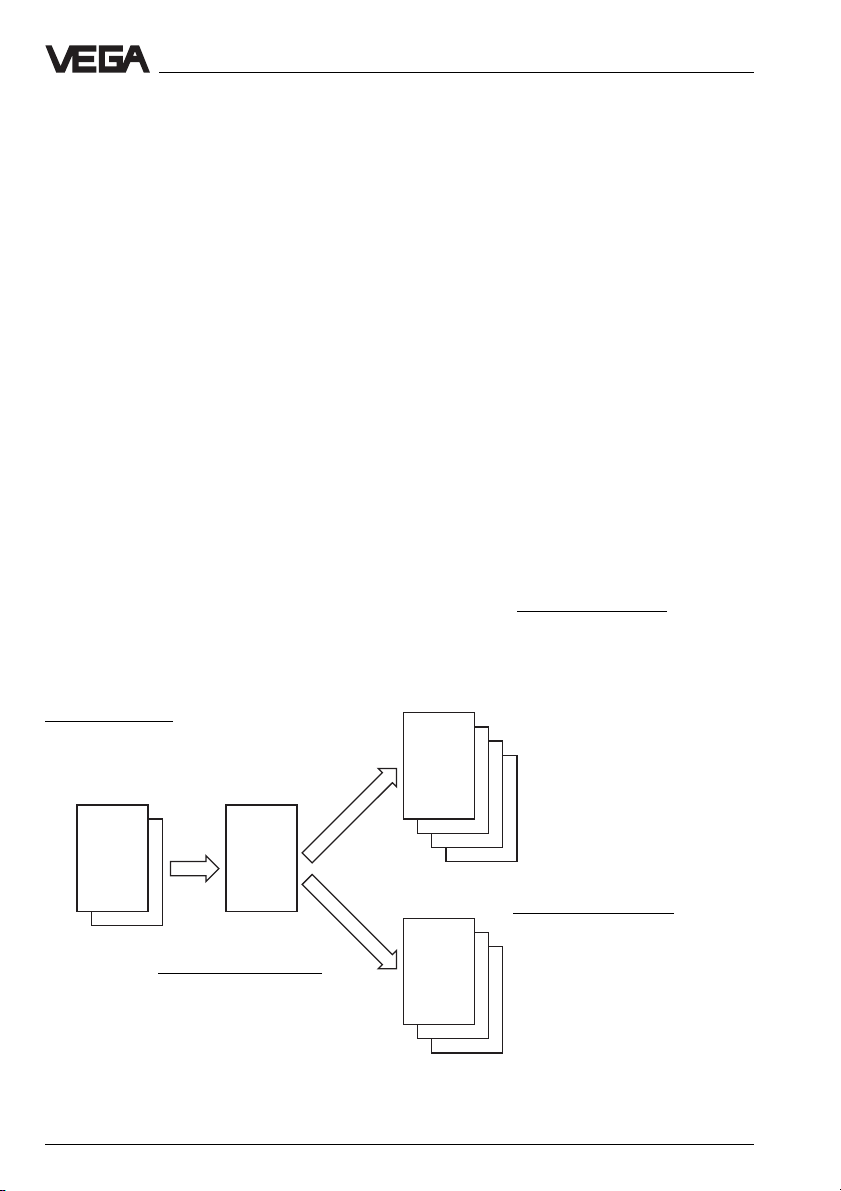
1.1 Function and configuration
VEGAMET 614 is a signal conditioning instrument for a number of different applications,
e.g.:
- level measurement
- gauge measurement
- process pressure measurement
-etc.
Software configuration
Input component
- continuous current
input
- contact input
Function
The signal conditioning instruments power
the connected sensors and process their
analogue measuring data. The conditioning is
done by a special software consisting of
functional components (FB), input components (EB), output components (AB) as well
as DCS components (PB).
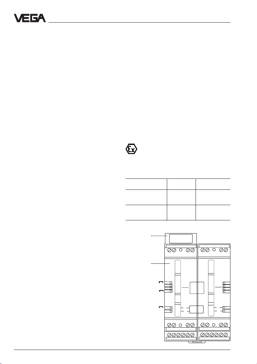
Configuration
The VEGAMET 614 signal conditioning instrument is a module unit with plug-in socket. The
front plate contains an adjustment module
with LC display and keys.
Output components
- current output
- voltage output
- DISBUS outputs
- failure output
- MET display
- relay outputs
AB
EB FB
PC/DCS components
- PC/DCS outputs
Functional component
- measurement loop
TAG 1
4 VEGAMET 614
PB
Page 5

Product description
1.2 Approvals
Ex approval
As an accessory, intrinsically safe instrument.
EC type approval certificate acc. to
CENELEC
II (1) G [EEx ia] IIC
WHG approval
Signal conditioning instrument as part of an
overfill protection system acc. to WHG applied for.
1.3 Features
- microcomputer-controlled signal conditioning instrument for continuous measurement
- adjustment module with LC display and 6
keys
- adjustable integration time
- two fixed and three user-programmable
linearisation curves
- fault monitoring
- fault signal and failure diagnosis via display
Input:
- 1 sensor input (capacitive electrode, pressure transmitter or other 4 … 20 mA sensor)
- 1 correction input (for key, switch or level
switch)
Outputs:
- 1 current output 0/4 … 20 mA
- 1 voltage output 0/2 … 10 V
- 2 relay outputs (spdt)
- 1 DISBUS output for digital wiring and for
connection of VEGADIS 174
- 1 fail safe relay
- adjustment also via PC with adjustment
software VVO; connection via the interface
adapter of the VEGACONNECT series
VEGAMET 614 5
Page 6

Product description
1.4 Technical data
Power supply
Operating voltage U
Power consumption approx. 10 VA or approx. 4 W
Meas. data input
Number 1 input
Input type active two-wire input, analogue (sensor is
Range 4 … 20 mA
Applicable sensors (loop powered) capacitive electrodes, pressure transmitters,
Voltage
- at 4 mA approx. 19.5 V DC
- at 20 mA approx. 16 V DC
Current limitation at approx. 26 mA, short-circuit-proof
Detection line break < 3.6 mA
Detection short-circuit > 21 mA
Min. adjustment delta 2 % of the entered sensor values
Connection cable 2-wire standard cable (screening
max. resistance per wire 35 Ω
Resolution 1 µA
Linearity error 0.025 % at 4 … 20 mA
Temperatur e error 0.04 %/10 K at 4 … 20 mA
= 20 … 250 V AC, 50/60 Hz
nom
= 20 … 72 V DC
powered by VEGAMET)
process pressure transmitters, differential
pressure transmitters,
ultrasonic sensor (4 … 20 mA sensor),
radar sensor (4 … 20 mA sensor)
recommended)
Current output
Number 1 output
Function analogue output of the processing results
Range adjustable between 0 … 20 mA
Load max. 500 Ω
Resolution 1 µA
Linearity error 0.05 % (relating to 20 mA)
Temperatur e error 0.05 %/10 K (relating to 20 mA)
Voltage output
Number 1 output
Function analogue output of the processing results
Range adjustable between 0 … 10 V
Current max. 1 mA
Resolution 0.5 mV
Linearity error 0.05 % (relating to 10 V)
Temperature error 0.06 %/10 K (relating to 10 V)
6 VEGAMET 614
Page 7

Product description
Relay outputs
Number 2 switching relays
1 fail safe relay
Contact floating spdt
Contact material AGSNO
Turn-on voltage min. 10 mV DC
, hard gold plated
2
max. 250 V AC/DC
Switching current min. 10 µA
max. 3 A AC, 1 A DC
Breaking capacitance max. 750 VA,
18 W at U = 60 V DC; 40 W at U ≤ 40 V DC
Min. switching hysteresis
(Low/High delta) 0.5 %
DISBUS output
Function for linking the signal conditioning instruments
and for connecting digital indicating
instruments
Connection cable 2-wire standard cable (screening is
recommended)
max. cable length 1000 m
Indicating elements
Clear text indication LC display
- 4-line, 6 digits each
- background lighting
Analogue indication LED chain consisting of:
- 11 segments 0 % … 100 %
- shows the actual value of the measurement
loop
LEDs in front plate green: operating voltage on
red: fault signal (LED lights with deenergised
relay)
yellow: relay status (standard setting:
LED lights with energised relay)
Adjustment elements
Front plate 6 keys for configuration and parameter
adjustment
Upper housing side rotary switch for adjustment of the instrument
address on DISBUS (in mounted status,
covered by plug-in socket)
Ambient conditions
Permissible ambient temperature -20°C … +60°C
Storage and transport temperature -40°C … +80°C
Electrical connection
Screw terminal max. 1.5 mm
VEGAMET 614 7
2
Page 8
Product description
Electrical protective measures
Instrument IP 30
Plug-in socket IP 20
Protection class II
Overvoltage category II
Electrical separating measures
Reliable separation acc. to
VDE 0106, part 1 between power supply, fail safe and level relay
and measuring data inputs
- reference voltage 250 V
- isolation resistance 2.3 kV
Galvanic isolation between relay outputs
- reference voltage 250 V
- isolation resistance 1.4 kV
Potential separation between DISBUS and outputs
- reference voltage 50 V
- isolation resistance 0.5 kV
Common reference potential at voltage and current output
Mechanical data
Series module unit with plug-in socket, including
transparent cover, sensor terminal cover,
coded pin, two jumpers
Mounting carrier rail mounting acc. to DIN 46 277, Bl. 3
Dimensions, unmounted W = 72 mm, H = 118.5 mm, D = 134 mm
Weight approx. 480 g
CE conformity
VEGAMET 614 and VEGAMET 614 Ex signal conditioning instruments meet the protective
regulations of EMC (89/336/EWG) and NSR (73/23/EWG). The instruments must only be
used in industrial areas. Conformity has been judged acc. to the following standards:
EMC Emission EN 50 081 - 2: 1993
Susceptibility EN 50 082 - 2: 1995
NSR EN 61 010 - 1: 1993
8 VEGAMET 614
Page 9
Product description
Ex technical data
Power supply
Operating voltage U
Reference voltage U
Meas. data input (intrinsically safe circuit)
Flame proofing II(1) G [EEx ia] IIC, [EEx ia] IIB
Max. values
- voltage U
- current I
- power P
Characteristics linear
Effective inner inductance L
Effective inner capacitance C
I
I
corresponds to non-Ex version
nom
= 250 V AC or 125 V DC
m
= 22.2 V
O
= 112 mA
O
= 620 mW
O
negligible
negligible
EEx ia IIC EEx ia IIB
Max. permissible outer inductance L
Max. permissible outer capacitance C
O
O
2 mH 10 mH
160 nF 1100 nF
The intrinsically safe circuits are reliably separated from the non-intrinsically safe circuits up
to a peak value of the nominal voltage of 375 V. The max. voltage on the non-intrinsically
safe circuits should not exceed 253 V
in case of failure.
eff
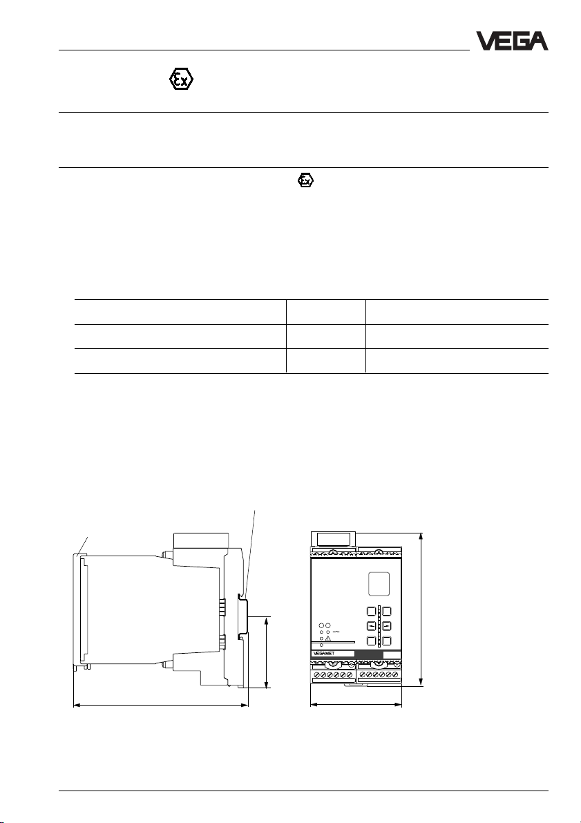
1.5 Dimensions
Carrier rail 35 x 7.5 or 35 x 15 acc.
to EN 50 022
Transparent cover
12
on
CONNECT
614
56 78
13 14 15 16
23 24 25 26 27 28
72
%
100
+
-
118,5
OKESC
Ser. No.
12345678
134
54,5
12 34
910 1112
17 18 20 21 22
VEGAMET 614 9
Page 10
2 Mounting and installation instructions
Mounting and installation instructions
Mounting
Each series 600 signal conditioning instrument consists of a plug-in socket for carrier
rail mounting DIN 46 277 and a module unit.
The supply voltage can be connected to
terminals 17 and 18.
For neighbouring series 600 signal conditioning instruments, it is possible to continue the
connection L1 and N directly via the supplied
jumpers. The same is valid for the connection
of VEGAMET voltage output 0 … 10 V (terminals 15 and 16) and for DISBUS output (terminals 9 and 10).
Note!
The jumpers must never be used with single
instruments or at the terminating end of an
instrument row. If this is not observed, there
is danger of coming in touch with the operating voltage or causing a short-circuit.
VEGAMET 614 Ex signal conditioning instrument is intrinsically safe and must not be
installed in hazardous areas.
Before setup, the Ex separating chamber
must be plugged into VEGAMET 614 Ex as
shown in the illustration.
Safe operation is ensured only if the operating instructions manual and the EC type
approval certificate are observed. VEGAMET
614 Ex must not be opened.
Coding
To avoid interchanging the various signal
conditioning instruments, the plug-in socket
is provided with pins and the signal conditioning instruments with corresponding gaps
(mechanical coding).
Instrument coding ensures through differently positioned coding pins that the various
series 600 signal conditioning instruments
are not interchanged.
An Ex coding with inserted coding pins ensures that the non-Ex and Ex instruments are
not interchanged.
On VEGAMET 614 Ex, the supplied
coding pins (instrument coding pin
and Ex coding pin) must be inserted
by the user according to the below table.
Instrument Ex
coding coding
VEGAMET 614 right 1 ––
VEGAMET 614 Ex right 1 left A
Separating chamber
(must always by
plugged in on the left
with Ex instruments)
Ex coding
Jumpers
Direct supply for
voltage output
0 … 10 V and
DISBUS
Direct connection
for supply voltage
left B
right B
left B
right B
VEGA
right
A o
VEGA
B o
C o
1 o
2 o
3 o
-
4 o
+
0…10 V
5 o
DISBUS
6 o
7 o
8 o
9 o
N
10 o
L1
11 o
12 o
left
A o
B o
C o
1 o
2 o
3 o
o
0…10 V
o
DISBUS
o
7 o
8 o
9 o
N
o
o
L1
12 o
-
+
10 VEGAMET 614
Page 11
Mounting and installation instructions
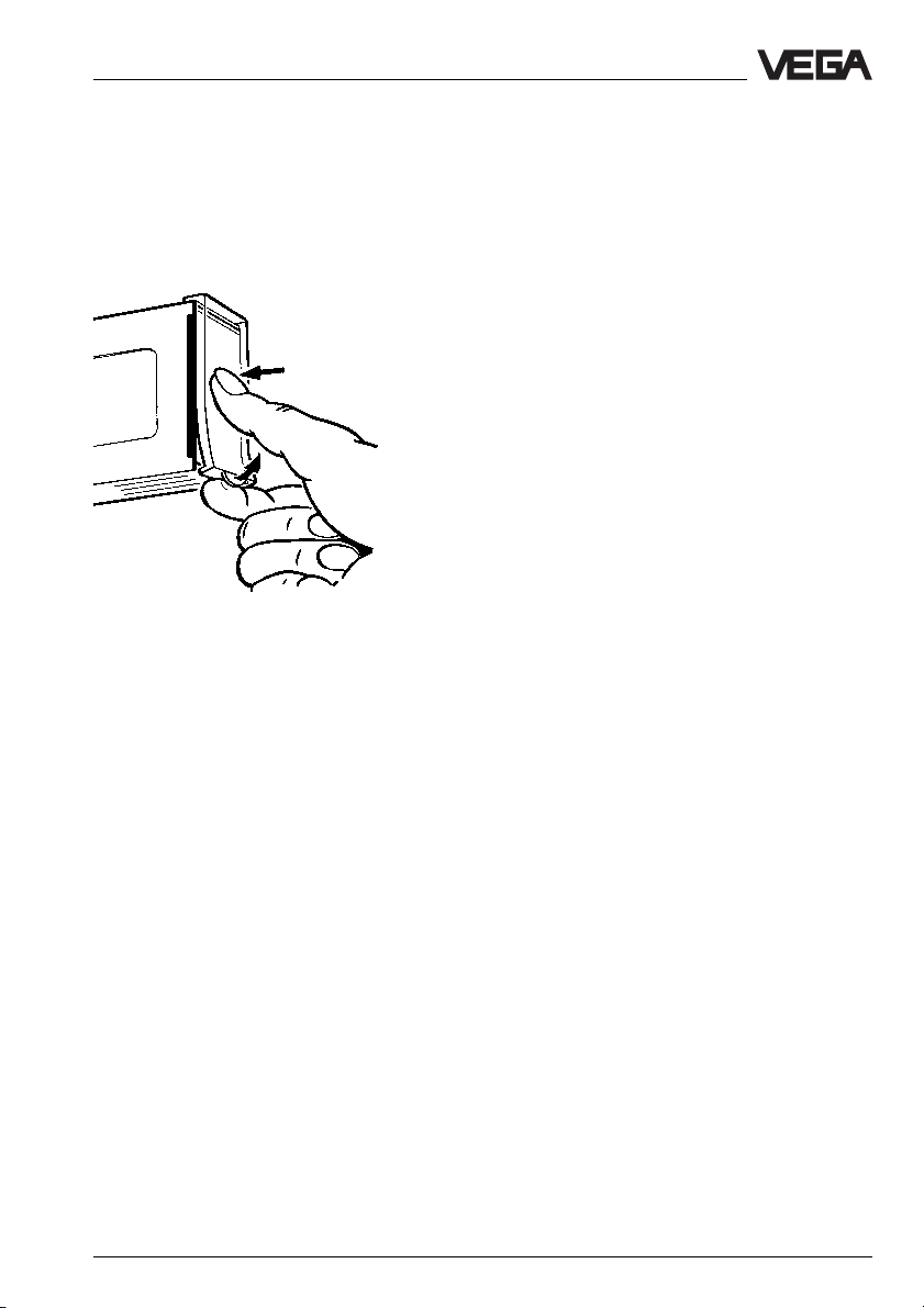
Transparent cover
To protect the instrument against unauthorized adjustment, the front plate of VEGAMET
can be equipped with two lockable transparent covers after setup. To remove the transparent cover, see illustration.
VEGAMET 614 11
Page 12
17 18 19 20 21 22
910 1112
12 34
23 24 25 26 27 28
13 14 15 16
56 78
L1
N
+- +-
+- +-
+-
3 Electrical connection
Electrical connection
3.1 Connection instructions
Note the following instructions for electrical
connection:
- The connection must be made acc. to the
local installation standards (e.g. in Germany acc. to the VDE-regulations).
- The wiring between VEGAMET 614 and
sensor can be made with standard twowire cable.
- If strong electromagnetic interferences are
expected, we recommend the use of
screened cable. The screening must be
earthed on both ends.
- The line resistances stated in the technical
data must not be exceeded.
- If overvoltages are expected, we recommend a sensor electronics with integrated
overvoltage protection or the installation of
VEGA overvoltage arresters.
3.2 Connection instructions for
Ex approved applications
When wiring between VEGAMET 614 Ex and
an explosion protected sensor, the installation
rules, in Germany acc. to VDE 165 and the
EC type approval certificate, must be observed. The official documents are supplied
with the respective instrument.
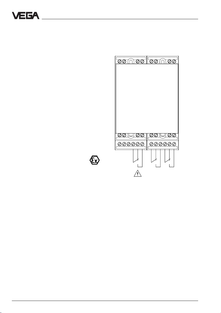
3.3 Wiring plan
Sensor
DISBUS
output
Power supply
Fail
safe
relay
The connections "9, 10, 15, 16, 17 and 18“ can be
connected with the supplied jumpers to neighbouring
series 600 signal conditioning instruments.
Level
relay 1
Current
output
Voltage output
Level
relay 2
Ex version
Before connecting Ex certified instruments,
please note the instructions in the attached
official documents as well as the valid installation regulations. Make sure that the Ex separating chamber is plugged in on the left
instrument side before setup (see illustration
Coding).
12 VEGAMET 614
Page 13
Adjustment
4 Adjustment
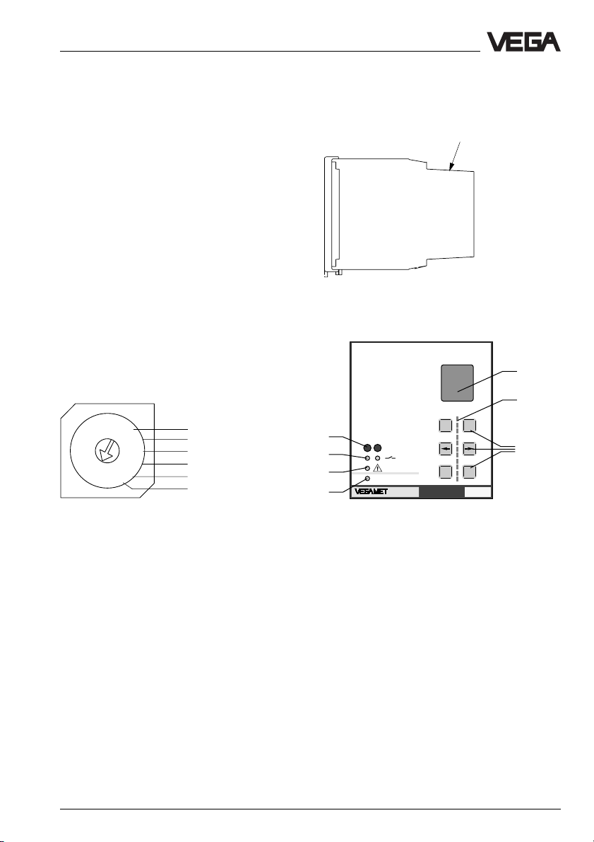
4.1 Indicating and adjustment elements
A rotary switch is located on the upper side
of the housing. It is used to set the instrument
address on DISBUS. This setting is necessary if several VEGAMET signal conditioning
instruments are linked via the DISBUS or if
you control a VEGADIS 174 indicating instrument via the DISBUS.
The adjustment range 1 … F corresponds to
the DISBUS addresses 1 … 15.
Factory setting: 1
Note:
If address 0 is set, the VEGAMET does not
participate in the DISBUS communication.
Rotary switch
8
9
7
6
5
4
33
A
B
C
D
E
2
F
1
0
10
11
12
13
14
15
Position of the rotary switch
Rotary switch
Front plate
%
100
+
4
5
6
7
CONNECT
12
on
614
-
OKESC
Ser.No.
12345678
1
2
3
The set instrument address on the DISBUS
can be indicated via the LC display.
Note
If several VEGAMET are linked via the
DISBUS, each address must be assigned
only once!
VEGAMET 614 13
1 LCD (4 lines with 6 figures each, illuminated) for clear text
indication
2 LED chain (yellow) for quasianalogue indication of the
measured value
3 Keys for menu adjustment
4 Connection socket for VEGACONNECT
5 LED (yellow) lights if the relay is energised (standard
setting)
6 LED (red), lights if fail safe relay is deenergised
7 LED (green), lights if operating voltage is on
Page 14
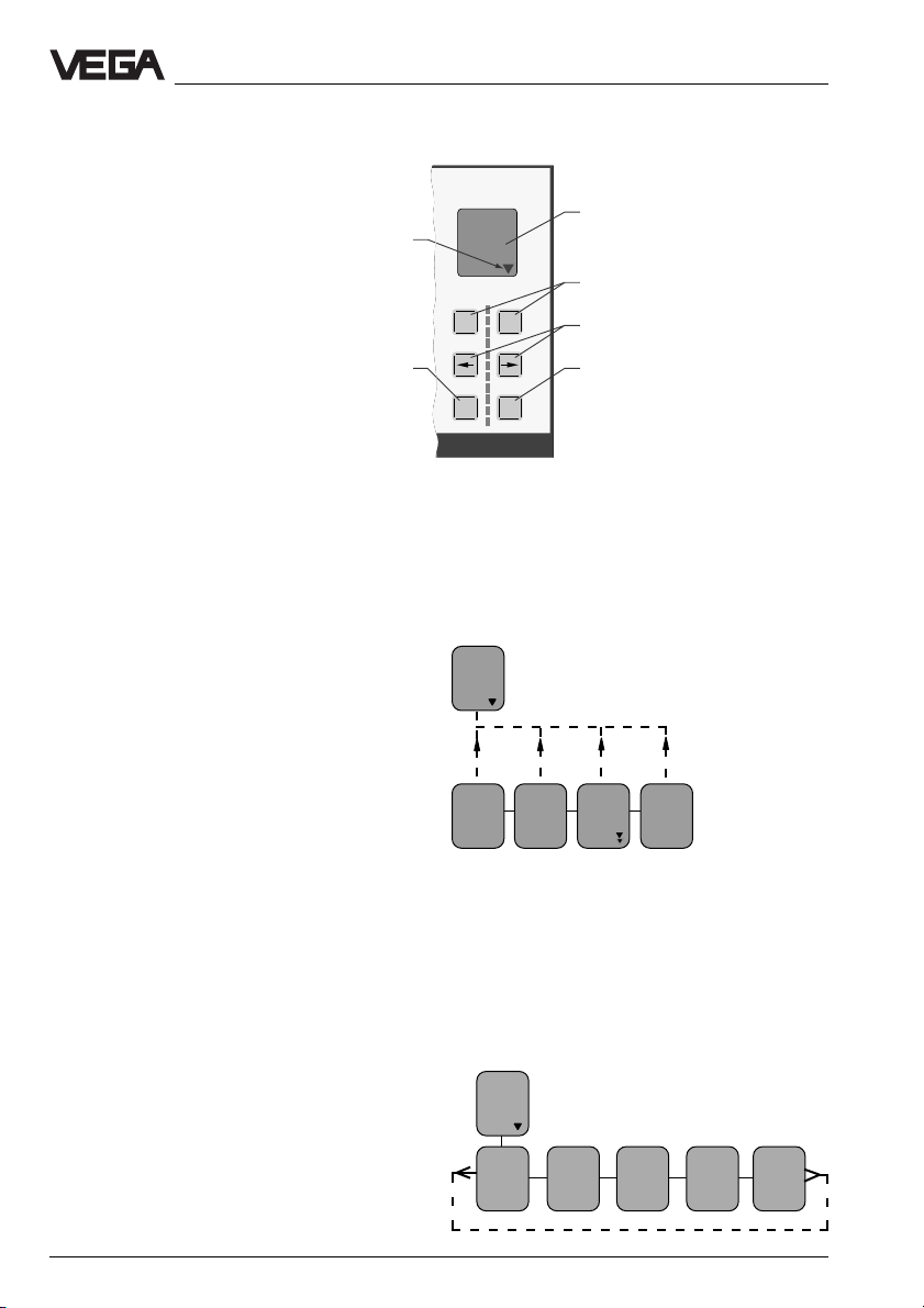
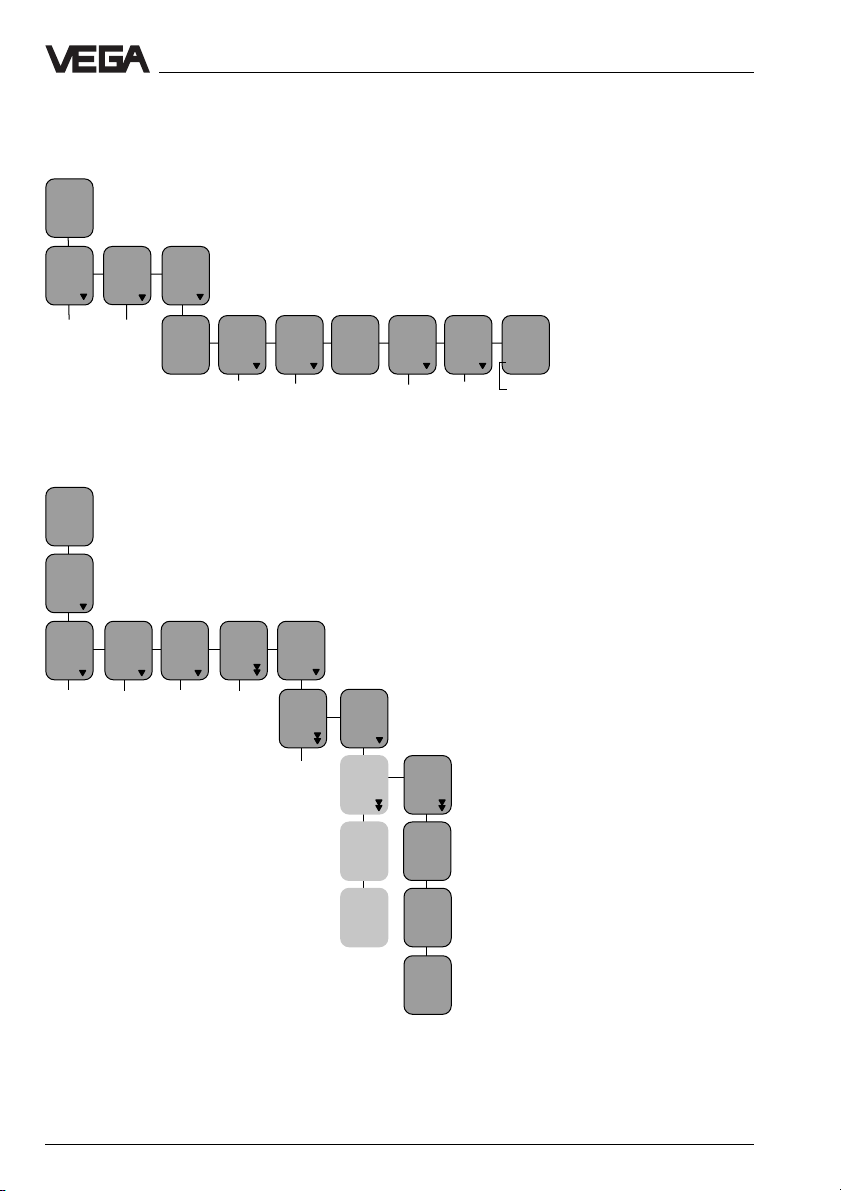
4.2 Adjustment system
Indicating and adjustment module
Branching point, i.e. jump to the
next lower menu with [OK]
Adjustment
Indication of
- measured value
- menu item
- parameter
%
100
+
-
Depending on the menu item, change
value or choose out of a list
Choose menu item
Depending on the menu item, interrupt
adjustment or change to the next higher
menu
Reduced menu - extended menu
Two menu systems are available: the "reduced menu“ and the "extended menu“.
Note:
VEGAMET 614 is preset to "reduced menu“
mode!
In the majority of applications, you can carry
out the necessary settings in this menu mode
(see also chapter 4.5 Comparison of the
menu modes).
Adjustment structure
The adjustment is made via 6 keys in conjunction with the text display. The jump from
the measured value display to the next lower
menu item is made with [OK]. Use [–>] or
[<–] to change within this menu level from
one menu item to the other. A branching point
is indicated by the symbol ▼ and enables
with [OK] a jump to the next lower menu item.
Parameters are indicated by the missing
symbol ▼. The value of the parameters can
be modified with [+] or [–] or chosen out of a
list. The modified value can be saved with
[OK]. To interrupt a setting (without saving
the modification), you have to push [ESC]. A
jump up to the next higher menu item is made
with [ESC]. 15 minutes after pushing a key
Depending on the menu item, save the
set value or change to the lower menu
OKESC
for the last time, an automatic reset to the
measured value display is triggered. A jump
up to the next higher menu level with [ESC] is
possible from each menu item, even if no
connection is shown in the menu schematics.
Add’l
function
ESC ESC
Password
off
ESC
Language
English
TAG 1
to de
fault
ESC
Menu
mode
Reduced
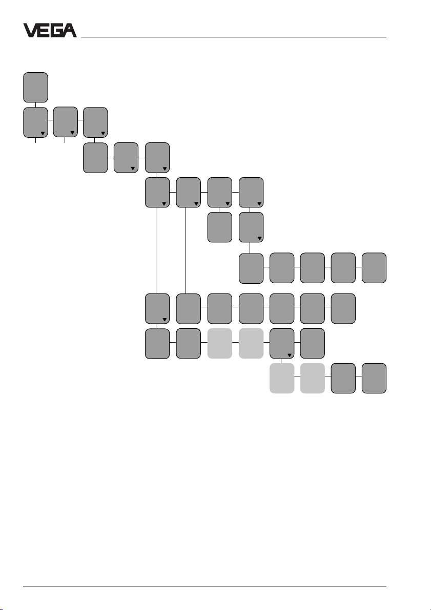
If you are in the utmost right menu item of a
menu row and push the [–>] key, you will
immediately reach the utmost left menu item
of this row. You also reach immediately the
right menu item from the left one, if you push
the [<–] key.
The connections (shown with a broken line)
are not shown in the menu schematics in
order to provide a clearer overview.
Volt
output 1
prop.
to
Percent
Unit
0,0%
Volt
output
0/10V
Failure
mode
0V
Volt
limitation
on
14 VEGAMET 614
Page 15
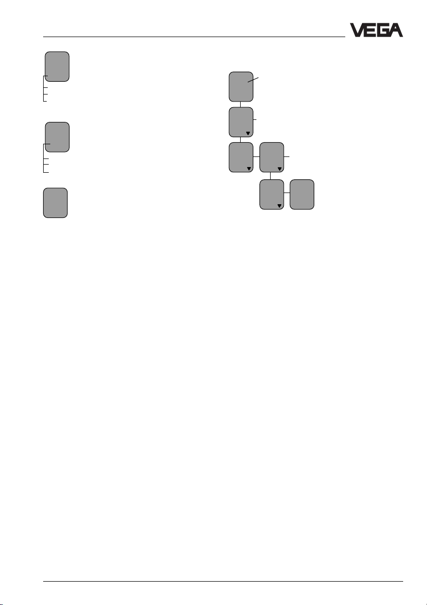
Adjustment
Formatting examples the menu
schematic
White letters indicate parameters
Language
which can be modified with the [+] or
Eng-
[–] key and saved with the [OK] key.
lish
Examples:
- In the menu item "Language“ you can
change from German to English.
Param.
Bolt print/italic inputs, e.g. the meas-
TAG -
urement loop name "TAG-No. 1" can
No. 1
▼
show a different text if you have
carried out a parameter adjustment
or configuration of the measurement loop. In
the menu schematics, you will see the factory
setting.
Volt
Light grey menu items are only dis-
at
played if necessary (depending on
0%
0,000
the adjustments in the other menu
items).
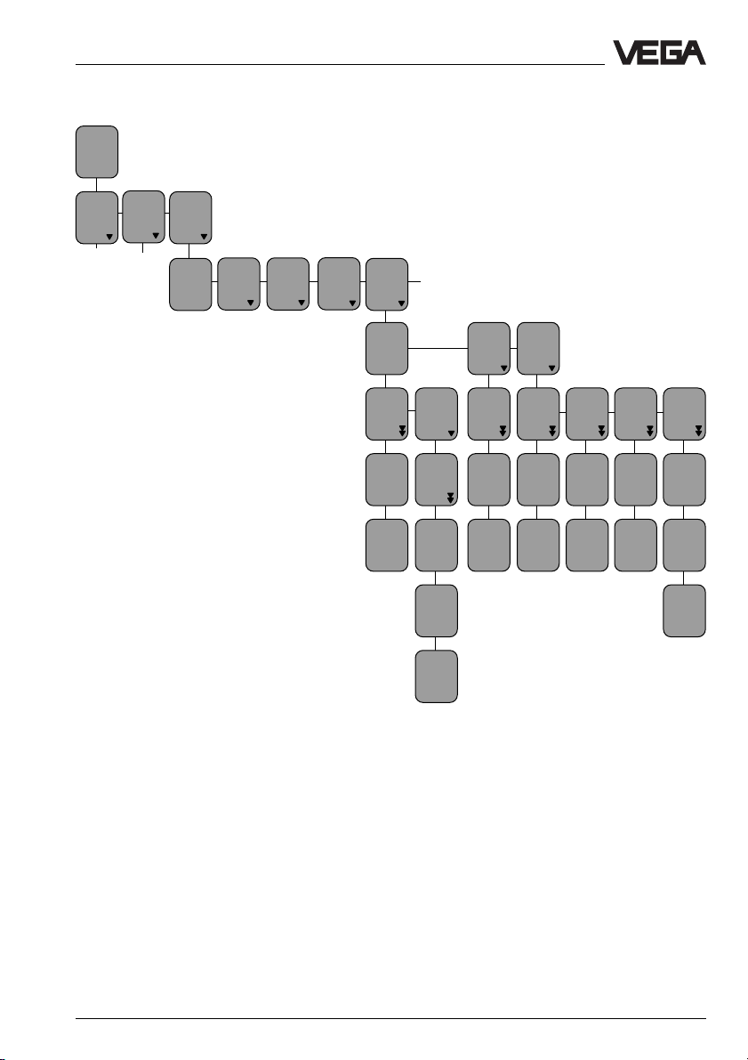
Changing the menu mode:
Move from the display of measured value
(TAG-No.1) to the menu item "Menu mode
reduced“. Now push [+] twice until "Menu
mode Extended“ appears, then push [OK].
You can now return to the measured value
indication by pushing [ESC] twice.
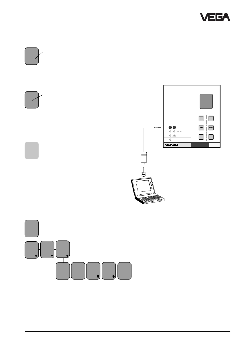
4.3 Adjustment via PC
Setup
- directly via the keys of the adjustment
module
- or with a PC, equipped with VVO software
(VEGA Visual Operating) and an interface
adapter VEGACONNECT.
%
100
+
-
CONNECT
12
on
614
VEGACONNECT
OKESC
Ser.No.
12345678
TAGNo. 1
%
xx,x
Add’l
Confi-
Param.
TAGNo. 1
guration
functions
Password
off
Language
English
TAG 1
to de
fault
Reset
TAG 1
Menu
mode
Reduced
VEGAMET 614 15
Page 16

Adjustment
4.4 Configuration and parameter adjustment
No matter whether you set up your
VEGAMET via the keys of the adjustment
module or via a PC with the software VVO,
the procedure is always the same.
Proceed in the following sequence:
- configuration (if not already configured with
a factory setting)
- parameter adjustment.
In this operating instructions manual, the
adjustment steps are described which are
directly carried out on the keys of VEGAMET.
The adjustment via the software VVO is described in a separate manual.
Configuration
Configuration means initial assigning or setting functions. VEGAMET requires a (mostly
once) basic co-ordination that determines the
applications and the assignments of the
inputs and outputs. Choices can be made
from existing functions and options. This
procedure is called configuration. The signal
conditioning instruments are delivered with a
configuration which only needs to be
changed in special cases.
The basic configuration includes the following
steps:
1 Configuration measurement loop
• Choose the kind of application (level,
gauge…)
• Choose sensor type (capacitive, hydro-
static…)
• Determine application (standard, level
difference…)
• Determine options (no option, correc-
tions…)
Note:
The measurement loop configuration can only
be modified, if a "Reset to single measurement“ has been carried out previously (under
"Additional functions“ in the extended menu).
If you only want to modify the sensor type,
you first have to carry out "Reset TAG 1“
(under "Additional functions“ in the reduced
menu).
2 Configuration of inputs
• Determine from where your VEGAMET
receives the input data (sensor, other
VEGAMET)
• Enter sensor characteristics values (meas.
range, current range)
3 Configuration of outputs
• All outputs (except fail safe relay) can been
assigned to one sensor or can be switched
off.
After basic configuration, VEGAMET goes
into operating mode and indicates the actual
measured value. The other configurations
should be carried out after the parameter
adjustment.
Parameter adjustment
Parameter adjustment means changing the
values. Signal conditioning instruments have
many parameters, the values of which can be
modified, such as for example, the integration
time of 0 … 600 s. The modification of these
values is called parameter adjustment. The
parameter adjustment does not influence the
configuration. Take note that parameter adjustment is only possible after a configuration
has been carried out (e.g. set values of the
current input after the current output has
been assigned).
16 VEGAMET 614
Page 17
Adjustment
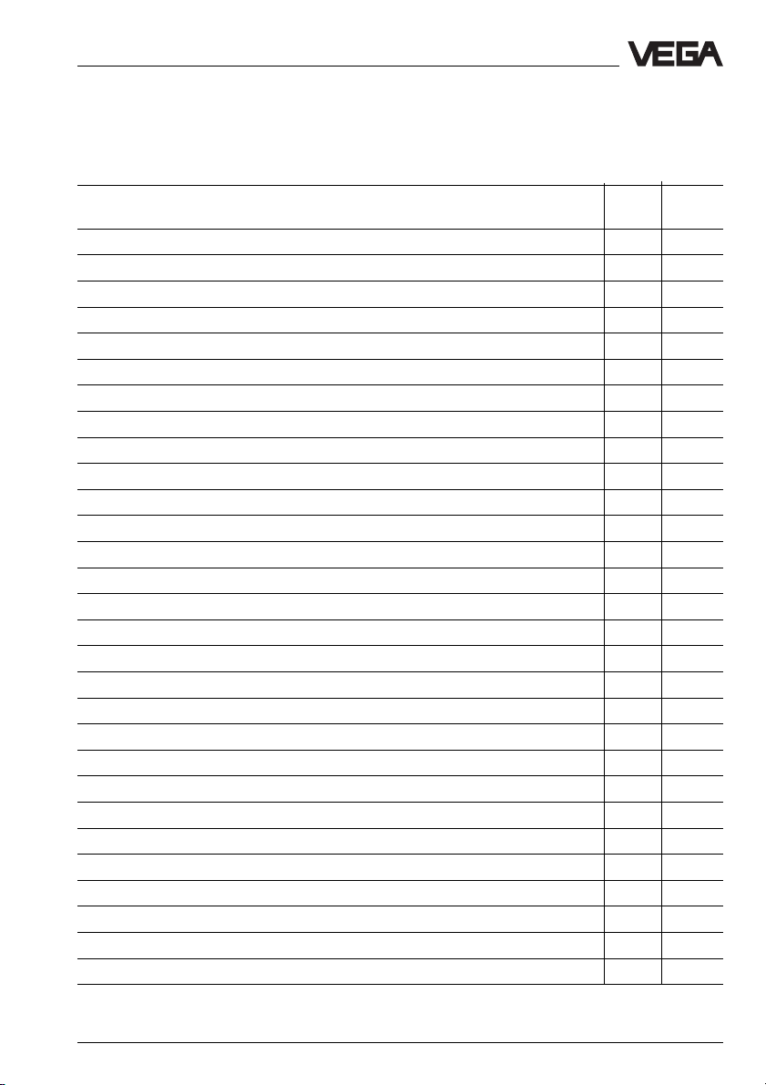
4.5 Comparison: reduced menu – extended menu
In the table the most important functions of VEGAMET 614 are listed – each with a mark indicating in which menu mode the functions are available.
Function Reduc. Ext.
Adjustment with medium x x
Adjustment without medium x x
Set integration time x x
Simulation xx
Switch over current output (4/20 mA, 0/20 mA, 20/4 mA, 20/0 mA) x x
Switch over voltage output (2/10 V, 0/10 V, 10/2 V, 10/0 V) x x
Switch over relay mode (overfill protection – dry run protection) x x
Scaling (display) x x
Change menu mode (reduced – extended) x x
Change menu language x x
Activate/deactivate password x x
Change sensor type x x
Change measurement loop name x x
Reset measurement loop (Reset TAG) x x
Reset measurement loop to default (TAG to default) x x
Edit linearisation curves – x
Change mode (e.g. level – gauge) – x
Select different reference values for outputs – x
Define output behaviour (current/voltage output) in case of failure – x
Adapt VEGAMET to sensor characteristics values – x
Offset correction during adjustment – x
Adjust relay switching delay – x
Reset level –x
Assign inputs (from another VEGAMET) – x
Switch on/off current/Volt limitation – x
Individual setting of current/voltage output values betw. 0 … 20 mA/0 … 10 V – x
Manual offset correction – x
Manual real value correction – x
Info indication – x
menu menu
VEGAMET 614 17
Page 18

5 Setup
• Set the VEGAMET instrument address on
the circuit board by means of the rotary
switch (only necessary, if several
VEGAMET are connected on the DISBUS).
• Install VEGAMET.
• Connect sensor and power supply.
• After switching on, the display indicates for
approx. 10 secs the instrument type and
the software version, e.g. "MET 614
V1.12“.
• If a measurement loop has not yet been
configured, the display shows "Configuration“, the red failure LED also lights. In this
case, proceed as described under "6.1
Configuration of measurement loop“.
• If a measurement loop has been
configured, the display shows a value, e.g.
"TAG-No. 1 21.8 %“.You can now carry out
the settings as described in the chapter "6
Settings in the reduced menu“.
Setup
18 VEGAMET 614
Page 19

Settings in the "Reduced menu“
6 Settings in the "Reduced menu“
6.1 Configuration of measurement loop
Choose sensor type
Meas.
TAG-
value
No. 1
%
indication
xx,x
Param.
TAGNo. 1
By default, VEGAMET 614 is configured for
connection to a hydrostatic pressure transmitter. If, for example, you use a capacitive
electrode, you have to proceed as follows:
Move to the menu item "Sensor type
Hydrostatic“.
Push [+] or [–] once. The word "Hydrostatic“
flashes. You are now in the editing mode.
Continue pushing [+] or [–] until the display
shows "Sensor type capacitive“. You are still
in the editing mode.
Now push the [OK] key. By doing this, you
save the settings and quit the editing mode.
Add’l
Confi-
func-
gura-
tions
tion
Password
off
Sensor
type
It is only possible to
Hydro-
modify the sensor type,
static
when a "Reset TAG 1“ was
capa-
carried out before.
citive
VEGADIF
Language
English
TAG 1
to de
fault
Reset
TAG 1
Delete
TAG 1
?
Reset
OK ?
Reset
Now!
OK ?
Name measurement loop
TAGNo. 1
%
xx,x
You can modify the measurement loop name "TAGNo. 1“, if you want a more
useful designation.
Param.
TAGNo. 1
Configuration
Two lines with six figures
each are available. To do
this, move to the menu item
"TAG name …“.
TAGName
TAG No. 1
TAG-
Push [+] or [–] once. The first char-
Name
acter of the measurement loop name,
TAG -
No. 1
in this example the letter T, flashes
(editing mode). Continue pushing the
[+] or [–] key, by doing this you scroll
through the alphabet, through the row of
numbers and through a list of characters.
TAG-
When you have reached the re-
Name
quested character, push [–>]. The
TAG No. 1
next character is activated and be-
gins flashing. Scroll again with [+]
and [–] to the requested character. With [–>]
you can move to the next character.
TAG-
If you have finished the last position
Name
of the name and you have "written"
Ves.4
the name of the measurement loop in
Hall3
this way, you have to push [OK] to
save the setting. If you quit the menu item
without saving, the name of the measurement
loop is again "TAG-No. 1“.
In the display of measured value and
Ves.4
Hall3
in all other menu items in which the
%
measurement loop name is shown,
27.8
you will now find the new designation.
VEGAMET 614 19
Page 20

Settings in the "Reduced menu“
6.2 Adjustment with medium
You can either carry out the adjustment with
medium or without medium. Adjustment with
medium means that you carry out the adjustment taking the actual level into account. To
carry out an adjustment with medium, it is
necessary to know the percentage value of
the actual vessel filling.
TAGNo. 1
%
xx,x
Param.
TAGNo. 1
Adjustment
with
medium
Min-
Max-
adjust
adjust
at %
at %
100,0
0,0
In this procedure, the percentage values
which correspond to the actual min. and max.
fillings are entered. It doesn't matter if you
enter first the min. value or the max. value. If
you know, for example, that your filling is
actually 80 %, you can enter in the menu
"max. adjustment" the value "80“. Later, when
your filling is, for example, 10 %, you enter in
the menu "min. adjustment" the value "10“.
Adjustment example
You know that your vessel is actually
Maxadjust
filled up to 80%. Move to the menu
at %
item "Max. adjust at % 100.0“. Push
100,0
the [–] key briefly, so that the figure
100.0 flashes (editing mode).
Continue pushing [–] until the figure
Maxadjust
80.0 appears on the display. Now
at %
push [OK] to save the adjustment.
80,0
Later, when your filling is, for exam-
Minadjust
ple, 10 %, go to the menu item
at %
"Min. adjust at % 0.0“. Briefly push
0,0
[+], until the figure 0.0 flashes
(editing mode).
Continue pushing [+] until "10“ ap-
Minadjust
pears on the display. Now push [OK]
at %
to save the adjustment.
10,0
You can, of course, carr y out the adjustment
with medium at 0 % and 100 % filling. Note:
The figures 0 % and 100 % must flash (editing mode), before they can be saved with the
[OK] key.
The bigger the difference between the two
adjustment points, the more precise the
measurement over the whole measuring
curve. An adjustment at 0 % and 100 %
would be ideal. For practical reasons, it is not
always possible to completely empty or fill a
vessel. The distance between the two adjustment points, however, should be at least
10 % of the sensor range.
20 VEGAMET 614
Page 21

Settings in the "Reduced menu“
6.3 Adjustment without medium
Meas.
TAG-
value
No. 1
indication
%
xx,x
Param.
TAGNo. 1
Adjustment
with
w.o
medium
medium
0%
100%
at
at
mA
mA
4,000
20,000
For this adjustment procedure, you have to
enter two sensor current values (4 … 20 mA)
corresponding to the levels 0 % and 100 %.
Adjustment example
You know the data of the sensor, i.e. you
know that at 0 % filling, the sensor delivers a
current of 4.2 mA and at 100 % filling a current of 15.5 mA. Enter these values in the
menu items.
15.5 mA at 100 %
4.2 mA at 0 %
0%
at
mA
4,200
100%
at
mA
15,500
Enter in these two menu items the values of
the senor. Use the [+] and [–] keys to set the
values and [OK] to save the values.
VEGAMET 614 21
Page 22

Settings in the "Reduced menu“
6.4 Scaling
TAG-
Meas.
No. 1
value
%
indication
xx,x
Param.
TAGNo. 1
Signal
Ad-
condit-
just-
ioning
ment
Integr
Scal-
ation
ing
time s
0
0%
100%
Decicorres
ponds
corres
ponds
1000
0
mal
point
888,8
prop.
to
unde
fined
The adjustments under scaling determine
which number values and which unit will be
actually displayed on the measured value
indication (upper menu item). In the menu
items "0 % corresponds…“ and "100 % corresponds…“ you can enter with [+] or [–]
and [OK] values which should be displayed
at 0 % and at 100 % filling. In the menu item
"Decimal point…“ you determine the position
of the decimal point. In the next menu item
"prop. to…“ you can select from a list of parameters: percent, mass, volume, pressure
etc. After pushing [+] or [–] save with [OK].
According to this adjustment, the menu item
"Unit…“ provides a new choice, e.g. m, dm,
cm, mm, ft, yd and in, if you have selected
the parameter "Height“ (compare chapter "8
Measured quantity and units“).
Unit
– –
Scaling example
You have a raised tank and you want the
level to be indicated in meters with three
digits after the decimal point.
100 %
h=4.5 m
0 %
2.341 m
0%
corres
ponds
1500
Enter the number 1500 (with keys
[+], [–] and [OK]) in this menu item.
This corresponds to the level at 0 %
(if you want to have a lower resolution
h=1.5 m
of the meas. value indication, you can also
enter 150 or 15).
100%
Enter the number 4500 (with keys
corres
[+], [–] and [OK]) in this menu item.
ponds
This corresponds to the level at
4500
100 %.
Adjust the decimal point as shown
Decimal
(with keys [+], [–] and [OK]).
point
8,888
22 VEGAMET 614
Page 23
Settings in the "Reduced menu“
prop.
to
Height
Percent
Pressure
Mass
Unit
m
dm
cm
….
TAG No. 1
2,341
Choose the term "Height“ in this
menu item (with keys [+], [–] and
[OK]).
If you have chosen "Height“ in the
previous menu item, you get a
choice of several units (mm, dm,
cm, m, yard…). Choose m (with the
keys [+], [–] and [OK]).
You can now see the scaled value in
the measured value display
m
6.5 Integration time
Meas.
TAG-
value
No. 1
%
indication
xx,x
Param.
TAGNo. 1
Signal
Ad-
condit-
just-
ioning
ment
Scal-
Integr
ing
ation
time s
0
If the integration time is set to 0 s (factory
setting), each quick change of the product
surface (e.g. waves) will be immediately
detected and interpreted as level change. All
output values of VEGAMET will follow the
wave movements. To avoid this, the integration time can be increased (max.
600 s are possible with VEGAMET). The
higher the time adjustment, the slower the
measurement reacts.
VEGAMET 614 23
Page 24

6.6 Outputs
Meas.
TAG -
value
No. 1
indication
%
xx,x
Param.
TAGNo. 1
Adjustment
Signal
conditioning
Outputs
Settings in the "Reduced menu“
Curr.
output 1
4/20mA
0/20mA
20/4mA
20/0mA
Volt
output
1
0/10V
10/2V
10/0V
2/10V
Relay
output
1
Mode
Overfill
protec.
Dry run
protection
Relay
output
2
Mode
Overfill
protec.
Dry run
protection
Low
%
0,0
The current output of VEGAMET is set to
4 … 20 mA. By pushing [+] or [–] and [OK]
you can set the output to the following values:
0/20 mA, 20/4 mA and 20/0 mA.
Beside the preadjustment (0/10 V), the following options are available for the voltage output: 10/2 V, 10/0 V and 2/10 V.
As a factory setting, the relay outputs are set
to mode "Overfill protection“ (mode A). By
pushing [+] or [–] and [OK] you can assign
the mode "Dry run protection“ (mode B)
separately for each relay output. In the next
menu items, you can determine the upper
and lower switching points for the set mode.
The graphics on the right show the behaviour
of the relay outputs and LEDs depending on
the level.
High
Low
%
%
100,0
0,0
High
%
100,0
Overfill protection
Parameter
High
Low
Relay output
t
The relay of relay output 1 deenergises at the
switching point "High“ (safe switching condition).
Dry run protection
Parameter
High
Low
Relay output
t
The relay of relay output 1 deenergises at the
switching point "Low“ (safe switching condition).
24 VEGAMET 614
Page 25

Settings in the "Reduced menu“
6.7 Simulation
Meas.
TAG-
value
No. 1
%
indication
xx,x
Param.
TAGNo. 1
Adjustment
Signal
conditioning
Outputs
Simulation
Simulation
Now !
OK ?
Simulation
%
xx,x
To check outputs and connected instruments,
you can adjust any individual percentage
value with the keys [+] and [–] in this menu
item. Initial point is always the actual measured value. The indicated value flashes when
simulation is activated. 15 minutes after setting the simulated value, the simulation automatically terminates and resets to meas.
value indication.
6.8 Password, language, default, reset, menu mode
Password
You can also protect VEGAMET 614 against
unauthorised or incorrect adjustment. Activate in the menu "Password“ the option "on“
(with keys [+], [–] and [OK]). Now, you can
only check the meas. value on the display.
You can still reach any menu item with the
arrow and OK keys, but as soon as you try
to modify an adjustment, you are asked for
the password. Enter the number "614“ (with
the keys [+], [–] and [OK]), to carry out the
adjustment. Entering the password once is
sufficient to open all protected menu items.
Language
In the menu item "Language“, you can
choose a language other than German such
as English, French etc. as menu language
(with keys [+], [–] and [OK]).
Reset
In the menu item "TAG 1 to default“ you reset
all settings relating to measurement loop 1 to
default. If, for example, you have changed
the name of the measurement loop to "Silo 5“,
after the reset, the name is again "TAG-No.
1“. Also, all adjustment values that you have
entered for measurement loop 1 are now
reset to default.
Meas.
TAGNo. 1
%
xx,x
Param.
TAG No. 1
value
indication
Configuration
Add’l
functions
Password
on
off
Language
English
French
German
etc.
TAG 1
to de
fault
Reset
OK ?
Reset
Now !
OK ?
Reset
TAG 1
Menu mode
The menu modes "Reduced“ and "Extended“
are available. With the keys [+], [–] and [OK]
you choose the required menu mode. The
menu schematics of the reduced menu and
the extended menu are shown later in this
Menu
operating instructions manual. The factory
mode
Redu-
setting is "Reduced menu“.
ced
Extended
VEGAMET 614 25
Page 26
7 Settings in the "Extended menu“
7.1 Configuration of measurement loop
TAG No. 1
%
xx,x
Param.
TAGNo. 1
Configuration
Config
inputs
Config
meas.
loop
TAG 1
Level
Settings in the "Extended menu“
Mode
Standard
Difference
Option
no
options
Application
Level
Gauge
Pressure
Sensor
type
Hydrostatic
Capac.
VEGADIF
VEGABAR
The measurement loop configuration is usually provided as factory setting. Should a
fundamental modification of the measurement
loop configuration be necessary, a "Reset to
single measurement“ must be carried out first
(in the menu "Additional functions“, "Reset
VEGAMET“). Only then can you modify the
adjustments in the menu items Application,
Sensor type, Mode and Option. You should,
therefore, work through the individual menu
items in the given sequence. The selection or
adjustment options always depend on the
adjustment in the previous menu item. If, for
example, in the menu item Application "Level"
has been set, only a sensor type that is suitable for level detection can be selected in the
menu item "Sensor type".
As soon as you have carried out and confirmed an adjustment in the menu item "Option“, the following message appears on the
display: "TAG being created!“.
TAG-
Sensor
coordination
Position A
Input
no.1
name
TAG No. 1
Failure
mode
on
off0/4-20mA
You choose the application 4/20 mA if you
want to connect an analogue ultrasonic sensor, an analogue radar sensor or a sensor of
another manufacturer to the VEGAMET.
In the following illustrations, further application modes are shown. In addition, you will
see there which adjustments you have to
carry out in the menu items "Sensor type“
and "Mode“.
In the menu item "TAG-Name“ you can assign
any name to the measurement loop (see
chapter "5.2 Standard menu“).
If you chose "Failure mode off“, the fail safe
relay and the failure indication on the front
plate become nonoperatable.
26 VEGAMET 614
Page 27

Settings in the "Extended menu“
Pos. A
Level measurement
Application: Level
Sensor: Capacitive electrodes
Hydrostatic pressure transmitters
Differential pressure transmitters
Mode: Standard
Option: none
Parameter: TAG1 level
Gauge measurement
Application: Gauge
Sensor: Hydrostatic pressure transmitters
Mode: Standard
Option: none
Parameter: TAG1gauge
Process pressure measurement
Application: Pressure
Sensor: Process pressure transmitters (VEGABAR)
Differential pressure transmitters (VEGADIF)
Mode: Standard
Option: none
Parameter: TAG1 process pressure
Pos. A
Pos. A
Level measurement
Gauge measurement
Pos. A
Pos. A
Process pressure measurement as
standard pressure measurement
Differential pressure measurement
Pos. A
Application: Pressure
Sensor: Differential pressure transmitter (VEGADIF)
Mode: Difference
Option: none
Parameter: TAG1 pressure difference
Process pressure measurement as
differential pressure measurement
VEGAMET 614 27
Page 28

7.2 Configuration of inputs
TAG No. 1
%
xx,x
Param.
TAGNo. 1
Configuration
Config
inputs
Input
no. 1
Settings in the "Extended menu“
Input
from
local
Met
MET02
MET03
MET04
….
Channel no.
S1
Input
undefined
Input1
Input2
Input3
Sensor
characteristics
Min.
meas.
range
0,00
Max.
meas.
range
1,00
Input local MET:
Here you can call another VEGAMET (e.g.
Met 05) and thereby specify that the input
signal is not taken directly from a connected
sensor, but from a VEGAMET connected via
DISBUS (e.g. VEGAMET 614). The called
VEGAMET number corresponds to the
DISBUS address of the instrument (see
chapter 4.1).
CONNECT
12
on
614
Min.
sensor
value
4,000
Max.
sensor
value
20,000
If another VEGAMET has been selected, the
menu item "Input undefined" appears in which
you can set the input number of the other
VEGAMET (see illustration).
The menu items "Min. meas. range“ and
"Max. meas. range“ are only visible with
hydrostatic pressur e transmitters. You can
obtain the relevant sensor data from the test
certificate of the hydrostatic pressure transmitter.
DISBUS
TAGNo. 1
%
35,9
%
100
+
-
CONNECT
OKESC
Ser.No.
12345678
12
on
Eingang
Ein-
gang1
%
100
+
-
OKESC
614
Ser.No.
12345678
MET 05
Input 1
"local MET“
28 VEGAMET 614
Page 29
Settings in the "Extended menu“
7.3 Configuration of outputs
TAG No. 1
%
xx,x
Param.
TAGNo. 1
Configuration
Config
inputs
Config
meas.
loop
Config
outputs
Config
curr.
output
Curr.1
to
TAG No. 1
----
Config
Volt
output
V olt1
to
TAG No. 1
----
PC/DCS output and DIS output:
The PC/DCS signal as well as the DIS signal
are transmitted via the DISBUS. The PC/DCS
output delivers output signals from
VEGAMET to the interface converter
VEGACOM 557. This interface converter
transfers the signals of VEGAMET via different standard protocols to connected systems (DCS/DCS). In the menu items "DCS 1
to“ up to "DCS 3 to…“ the measurement loop
can be assigned or switched off.
Config
relay
output
Operating
relay
Rel. 1
to
TAG No. 1
---- ----
Fail
safe
relay
Relay
Standard
Rel. 2
to
TAG No. 1
Config
PC/
DCSoutp.
PC/
DCS
meas.
values
DCS
1 to
TAG No. 1
----
Config
VEGADIS
DIS 1
to
TAG No. 1
----
PC/DCS
relay
status
off
DCS
2 to
----
DIS 2
to
----
PC/DCS
input
status
off
DCS
3 to
----
Up to three external indicating instruments
(VEGADIS 174) can be connected to
DISBUS. In the menu items "DIS 1 to…“ up to
"DIS 3 to–“ the measurement loop can be
assigned or switched off.
In the factory setting, the current, volt and
relay outputs are assigned to measurement
loop "TAG-No. 1“. All outputs can be individually switched off (----), i.e. prevented from
accessing a measurement loop.
DIS 3
to
----
In the menu items "PC/DCS relay status“ and
"PC/DCS input status“, it can be specified
that the relay mode and input status will also
be transmitted via the DISBUS.
VEGAMET 614 29
Page 30
7.4 Adjustment
TAG No. 1
%
xx,x
Param.
TAGNo. 1
Adjustment
Settings in the "Extended menu“
with
medium
Minadjust
at %
0,0
Max adjust
at %
100,0
w.o.
medium
Adjustment
mA
Offset
correction
Sensor
pressur’d ?
OK ?
Offset
corr.
Now !
OK ?
0%
at
mA
4,000
100%
at
mA
20,000
The adjustment with medium corresponds
to the procedure in the reduced menu (see
appropriate chapter).
- if the medium is changed later on (medium
with another density value or DK value)
and no new adjustment can be made
or
- if the MET indication and the DIS outputs
relate to height in meters
note the following:
In applications with hydrostatic pressure
transmitters, the adjusted density value (see
menu "Parameter, Signal conditioning“) must
correspond to the value of the medium. In
applications with capacitive electrodes, the
adjusted DK value must correspond to the
value of the medium.
For the adjustment without medium, two
anticipated values for level, gauge etc. must
be adjusted corresponding to 0 % and 100
% must be entered.
The menu item "Offset correction“ is activated
when hydrostatic pressure transmitters are
connected. The offset correction should be
carried out after installation of the sensor as
the sensor values can differ slightly due to
varying installation positions (vertical or horizontal installations). With the offset correction,
the meas. data of the unpressurised sensor
(vessel empty) are detected as correction
values and taken into account in subsequent
measurements.
30 VEGAMET 614
Page 31

Settings in the "Extended menu“
7.5 Conditioning
TAG No. 1
%
xx,x
Param.
TAG No. 1
Adjust-
Signal
ment
conditioning
Scaling
0%
corresponds
0
Integr
Lin.
ation
curve
time s
0
linear
spherical tank…
Deci-
100%
mal
corres-
point
ponds
888,8
1000
Density
in
Kg/dm
1,000
prop.
to
undefined
Meas.
DK
value
value
limita-
(Er)
3
81,00
Unit
– –
tion
negative
values
yes
Failure
mode
Stan
dard
>110%
The menu items "Scaling“ and "Integration
time“ corresponds to the menu items in the
"reduced menu“ (see appropriate chapter).
The menu items "Density…“ or "DK value… “
are displayed as options when under "Configuration measurement loop“ the appropriate
sensor type has been selected. The density
or DK value must, before adjustment with
medium, be so adjusted that it corresponds
to the value of the medium (water has a density of 1.0 kg/dm
3
and a dielectric value of
81.00).
The following linearisation curves are available:
- linear (factory setting)
- horiz. cylindrical tank
- spherical tank
- Lin-curve 1
- Lin-curve 2
- Lin-curve 3
Lin-curves 1 … 3 can be edited by the
user (see appropriate chapter).
After scaling or linearisation, the required
output must be assigned to the scaled or
linearised value (menu item "prop. to..." and
"Unit...") in the menu range "Parameter adjustment of outputs".
Under Meas. value limitation, you can exclude negative values.
Failure mode Standard
means that at a sensor current of 3.6 mA or
21 mA, the fail safe relay responds.
Failure mode >110%
generates a fault signal if a meas. value of
more than 110 % or less than -10 % is
reached.
VEGAMET 614 31
Page 32

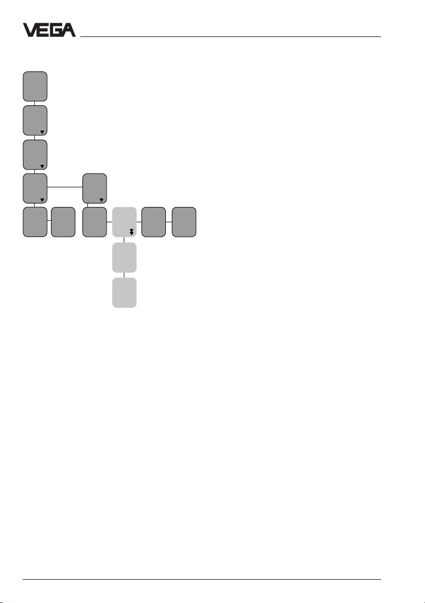
7.6 Parameter adjustment of outputs
Current outputs/Volt outputs
TAG No. 1
%
xx,x
Param.
TAG No. 1
Signal
conditioning
Outputs
Adjustment
Settings in the "Extended menu“
Current
outputs
Current
output
1
Volum e TARE%
prop.
to
Percent
Volt
outputs
Volt
output
1
prop.
to
Percent
Volum e TAR E %
Unit
0,0%
Unit
0,0%
Current
output
0/20mA
20/4mA
20/0mA
free
Volt
output
0/10V
10/2V
10/0V
2/10V
free
Current
at 0%
4,000
0,0
..20,0
In the menu item "prop. to“, you can choose
between percent and volume. "Prop. to volume“ is then useful when under "Signal conditioning - Linearisation curves“, for example, a
spherical tank or an individually defined
linearisation curve is selected. The output
current or the output voltage is then proportional to the volume of the tank contents.
Unit:
Selection list dependent on the choice in the
previous menu item "prop. to“ (see chapter "8
Measured quantity and units“).
Volt output/Current output:
If "free“ is chosen, the following (light grey)
menu items appear:
Volt
at
0%
0,000
0,0
..10,0
Current
at
100%
20,000
0,0
..20,0
Volt
at
100%
10,000
0,0
..10,0
Failure
mode
0mA
22mA
- 0%
100%
Failure
mode
0V
11V
- 0%
100%
Current
limitation
on
off
Volt
limitation
on
off
- Volt at 0 %/100 %:
Individual voltage values between 0 V and
+10 V can be set.
- Current at 0 %/100 %:
Individual current values between 0 mA
and +20 mA can be set.
Failure mode:
The height of the output current/output voltage in case of failure is determined. If "--“ is
chosen, the actual value is maintained.
Volt limitation/Current limitation on:
Voltage/current remain within the values
which are given in the menu item "Voltage
output/current output".
32 VEGAMET 614
Page 33

Settings in the "Extended menu“
Relay outputs
TAG No. 1
%
xx,x
Param.
TAGNo. 1
Adjustment
Signal
conditioning
Outputs
Current
outputs
Volt
outputs
Relay
outputs
Relay
output
1
prop.
to
Percent
Volume
Height
Pressure
Relay
output
2
like relay output 1
Unit
0,0%
0,00 %
Mode
Overfill
protec.
Dry run protection
Switching window on
Switching window off
Rising tendency
Falling tendency
In the menu item "prop. to“, you choose a
parameter to which the relay reacts. You can
choose between percent and volume ("prop.
to volume“ is useful when under "Conditioning
- Linearisation curves“, for example, a spherical tank or a user-programmable lin. curve is
selected). In the next menu item, you can
select the suitable Unit. In the menu item
"Mode“, the mode of the relay can be selected. The individual relay modes are described on the following pages.
If mode "Rising tendency“ or "Falling tendency“ is selected, the menu items "Deviation“, "Dev. per time“, "Cycle time“ and
"Number of cycles“ appear.
Low
%
0,0
High
%
100,0
Deviation
s
1,0
Deviation
per
time
Cycle
time
s
1
Failure
mode
off
hold
Number
of
cycles
10
Add’l
functions
Switching
delay
t on
s
0
t off
s
0
With all other modes, the menu items "Low“
and "High“ appear. There you can determine
the switching points for the relay.
The menu item "Failure mode“ always appears. "Failure mode off“ causes the relay to
deenergise when a failure (e.g. sensor
shortcircuit) occurs. "Failure mode hold“
causes the actual relay status to be maintained when a failure occurs.
Under "Add’l functions“ you can adjust a
switch on delay (t on) and a switch off delay
(t off) of the relay of max. 600 s (with the relay
modes "Rising tendency“ or "Falling tendency“ no switching delay can be set).
VEGAMET 614 33
Page 34

Settings in the "Extended menu“
Relay mode: overfill protection
The relay deenergises at switching point
"High“ (safe condition).
Relay mode: dry run protection
The relay deenergises at switching point
"Low“ (safe condition).
Relay mode: switching window on
The relay is energised within the switching
window.
Relay mode: switching window off
The relay is deenergised within the switching
window.
Parameter
High
Low
t
Relay output
Parameter
High
Low
t
Relay output
Parameter
High
Low
t
Relay output
Parameter
High
Low
t
Relay output
34 VEGAMET 614
Page 35

Settings in the "Extended menu“
Tendency determination
The level change within the cycle time (ta) is determined and after completion of all cycles (n),
an average value is generated out of the sum of the level changes. If this average value exceeds a previously defined % value, the tendency determination responds, i.e. an energised
relay deenergises. If "Rising tendency“ or "Falling tendency“ are selected, the menu items
"Deviation in %“ and "Deviation per time“ are activated.
%
t ges.
t
a
–– Mode Rising tendency
The relay deenergises when the
rising average value of "t tot.“
exceeds the previously defined %
value.
Falling tendency
Relay output
ta = cycle time
n = number of cycles
%
4 n=4
321
t ges.
t
a
same dependence, however with
falling average value
4 n=4
321
Relay output
ta = cycle time
n = number of cycles
–– Deviation in % 2 If the level change exceeds the % value set
here, the tendency determination responds.
0 … 110 %
Example 2 % (change) per t tot.
–– Deviation per time
t
t
–– Cycle time
in s 60 Adjustment range 0 … 999 s
Example 60 s correspond to 1 minute
–– Number of
cycles 4 Adjustment range 0 … 99 cycles
Example: t tot = ta • n = 60 • 4 = 240 s = 4 min,
i.e. after every 4 min., the average value of the
deviation is generated and the result is compared with the given deviation in %, here in the
example = 2 %
VEGAMET 614 35
Page 36
MET indication/PC/DCS outputs/DIS outputs
TAG No. 1
%
xx,x
Param.
TAGNo. 1
Settings in the "Extended menu“
Signal
conditioning
Outputs
Current
outputs
Volt
outputs
Relay
outputs
MET
indication
prop.
to
Percent
scaled
Height
…
Adjustment
MET indication/Unit:
In the menu item "prop. to“, you choose the
parameter to which the VEGAMET display
reacts (if you have carried out a scaling under the menu item "Signal conditioning“,
"prop. to scaled“ will have been automatically
set, i.e. the display will indicate the scaled
value). "Prop. to volume“ is then useful if you
have selected, for example, a spherical tank
or a user-programmable lin. curve under
"Signal conditioning - Linearisation curves“.
The indicated value of the VEGAMET display
then reacts proportionally to the volume of the
tank contents.
DIS
PC/
outputs
DCS
outputs
Unit
0,0%
DCS
output 1
prop.
to
Percent
scaled
Height
…
DIS
output
1
prop.
to
Percent
scaled
Height
…
Unit
DIS
DIS
output
output
3
2
like DIS output 1
Unit
0,0%
DCS
DCS
output
output
3
2
like DCS output 1
PC/DCS outputs and DIS outputs:
Are adjusted according to the same procedure as the MET indication.
36 VEGAMET 614
Page 37

Settings in the "Extended menu“
7.7 Simulation 7.8 Special function: Reset
TAG No. 1
%
xx,x
Param.
TAG No. 1
Out-
Adjustment
Signal
conditioning
puts
Simulation
Simulation
Now!
OK?
Simulation
%
XX,X
To check the outputs and connected instruments, you can adjust in this menu item any
individual percentage value with the keys [+]
and [–]. The starting point is always the actual measured value. The indicated value
flashes when the simulation is activated. 15
minutes after setting the simulated value, the
simulation is automatically terminated and the
display reset to measured value indication.
TAG No. 1
%
xx,x
Param.
TAGNo. 1
Out-
Simu-
Adjustment
Signal
conditioning
puts
lation
Special
functions
Reset
Level
Reset
OK ?
Reset
Now!
OK ?
With this reset, all parameter values of the
measurement loop TAG-No. 1 are reset to
factory settings (empty and full adjustment,
relay outputs, current output, volt output and
scaling of the meas. value indication are
reset).
VEGAMET 614 37
Page 38
7.9 Password, language, menu mode
See chapter "6 Settings in the Reduced menu“.
TAG No. 1
%
Param.
Configuration
Add’l
functions
Password
off
lin.
curve
InfoEdit
Lang-
Reset
uage
VEGA-
Eng-
MET
lish
TAGNo. 1
7.10 Special function: Manual correction
TAG Nr. 1
%
xx,x
Param.
TAGNr. 1
Adjustment
Signal
conditioning
Outputs
Simulation
Special
functions
Reset
Level
Manual
corr.
Manual offset correction
(only with hydrostatic pressure transmitters)
This correction can be carried out to compensate changes of the sensor values due to
ageing. In order to do this, the sensor must
be in an unpressurized condition (empty
vessel).
Manual real value correction
In the menu item "Correction % 0.0“, you can
enter a percentage value which corresponds
to the actual level.
Service
Settings in the "Extended menu“
Menu
mode
Extended
Reduced
Offset
correction
Offset
correction
OK?
Correction
Now !
OK ?
Real
value
corr.
Real
value
corr.
OK?
Correction
%
0,0
Correction
Now !
OK ?
38 VEGAMET 614
Page 39

Settings in the "Extended menu“
7.11 Linearisation curves
TAG No. 1
%
xx,x
Param.
Confi-
Add’l
guration
func-
tions
Pass-
word
off
Edit
lin.
curve
Lin.
curve1
TAGNo. 1
Lin.
curve2
Lin.
curve3
Add
lin.
point
x %
0,0
y V%
0,0
like LIN-curve 1
Edit
lin.
curve1
x 0 %
0,0
y 0 V%
0,0
x 1 %
100,0
y 1 V%
100,0
Index marker number (0…32)
Linearisation curve 1 … 3
A linearisation curve is generated by a certain number of index markers and their value
pairs. A value pair consists of a value for
level percent (X %) and a value for volume
percent (Y V %). Up to max. 32 index markers can be added. A linearisation curve can
be terminated after any individual number of
index markers. The signal conditioning instrument terminates the linearisation curve automatically with the values X = 100 % and Y
= 100 %.
The data for the value pairs can be determined by incremental filling or can be taken
from a table of values provided by the vessel
manufacturer.
An example of incremental filling
Initial situation:
- you have already carried out the 0 % and
100 % adjustment
- the total volume of the vessel is known to
you, for example 300 m
- the gauging volume in this example was
set at 15 m
3
3
Delete
lin.
point
x 2 %
100,0
y 2 V%
100,0
x 32 %
100,0
y 32V%
100,0
x 0,0
y 0,0
delete
Delete
Now?
x 100,0
y 100,0
delete
Delete
Now?
1st index marker
- fill the vessel with the liquid quantity of the
gauging volume of 15 m
3
- the value for level percent is indicated on
VEGAMET, transfer this value into the linearity protocol, column X %
- the value for volume percent must be calculated acc. to the following formula
100 % x gauging volume
Y 1 V = ––––––––––––––––––––––––
total volume
100 % x 15 m
= ––––––––––––––– = 5 %
300 m
3
3
Transfer this value also into the linearity
protocol, column Y V %.
2nd index marker, etc.
See also the following illustration.
VEGAMET 614 39
Page 40

Illustration of a linearisation curve
Settings in the "Extended menu“
X (in %)
100
80
60
40
20
Add
lin.
point
x %
0,0
y V%
0,0
With [OK] the new value pair
is automatically placed at the
correct position in the
linearisation curve. The already present index markers
are re-sorted.
0
X1 %
12,0
Y1 V %
5,0
Edit
lin.
curve 1
x 0 %
x 1 %
100,0
y 1 V%
100,0
x 2 %
100,0
y 2 V%
100,0
0,0
y 0 V%
0,0
Select the index markers
1 … 32 with [–>] or [<–], edit
the Y value with [+] or [–],
accept with [OK].
40 60 80 100
Delete
lin.
point
x 0,0
y 0,0
delete
Delete
now?
X32 %
100,0
Y32V %
100,0
x100,0
y100,0
delete
Delete
now?
To delete the index markers,
select the value pairs with [–
>] or [<–]. With [OK] the
value pair and the corresponding index marker are
deleted from the lin. curve.
The remaining index markers
move up.
V (in %)20
40 VEGAMET 614
Page 41

Settings in the "Extended menu“
Linearity protocol
A linearisation curve is entered in the menu item "Add. lin. point“.
Linearisation curve 1
Index Value pair
marker no. X % Y V %
1
2
3
4
5
6
7
8
9
10
11
12
13
14
15
16
17
18
19
20
21
22
23
24
25
26
27
28
29
29
30
31
32
Linearisation curve 2
Index Value pair
marker no. X % Y V %
1
2
3
4
5
6
7
8
9
10
11
12
13
14
15
16
17
18
19
20
21
22
23
24
25
26
27
28
29
29
30
31
32
Linearisation curve 3
Index Value pair
marker no. X % Y V %
1
2
3
4
5
6
7
8
9
10
11
12
13
14
15
16
17
18
19
20
21
22
23
24
25
26
27
28
29
29
30
31
32
Note
Date
Name
VEGAMET 614 41
Page 42
7.12 Info
TAG No. 1
%
xx,x
Param.
Configura-
TAG-
tion
No. 1
Add’l
functions
Settings in the "Extended menu“
Password
off
Lin.
curve
Info
Input
VEGA-
info
MET
info
Input1 Type
MET614
Sensor
type
hydrostatic
Input
from
local
MET
All menu items under "Info“ only have display
function.
Program
info
Program
info
xxxxxx
Serial
number
xxxx
xxxx
Channel no.
S1
Meas.
loop
info
TAG 1
TAG No. 1
Minadjust
at %
0,0
Instr.
addr.
Input
undefined
Minadjust
0,000
1
Min.
meas.
range
bar
Softw.
vers.
V1.13
06
Sensor
characteristics
0,00
Maxadjust
at %
100,0
Softw.
date
47/97
Actual
switch
status
xx,xxx
Max.
meas.
range
1,00
Maxadjust
bar
1,000
Param.
vers.
5
Min.
sensor
value
4,000
Parameter
Level
Max.
sensor
value
20,000
42 VEGAMET 614
Page 43
Settings in the "Extended menu“
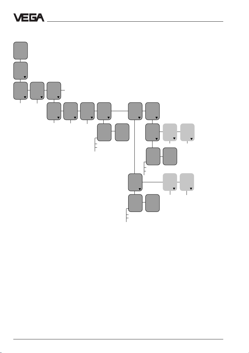
7.13 Reset VEGAMET
TAG No. 1
%
xx,x
Param.
Confi-
Add’l
guration
func-
tions
TAGNo. 1
Password
off
Lin.
curve
Lang-
Info Reset
uage
English
With the function "TAG 1 to default“, you
reset the whole configuration and all parameter adjustments to factory setting. However,
the basic configuration remains, e.g. "Level
measurement/Hydrostatic“.
With the function "Reset TA G 1“, the basic
configuration is also deleted. Then, the measurement loop must be created completely
anew (config. meas. loop).
With the function "Reset sensor values“, you
delete the entered sensor data of the connected sensor.
VEGAMET
Reset
Reset
TAG 1
Delete
TAG1?
Reset
OK?
Reset
Now!
OK?
Reset
sensor
values
Reset
input
1
Reset
OK?
Reset
Now!
OK?
lin.curves
Reset
lin.
curve1
Reset
OK?
Reset
Now!
OK?
Reset
lin.
curve2
Reset
OK?
Reset
Now!
OK?
Reset
lin.
curve3
Reset
OK?
Reset
Now!
OK?
Reset
configuration
TAG 1
to
default
Reset
OK?
Reset
Now!
OK?
to
single
meas.
With the function "Reset lin-curves“, you can
delete your manually edited linearisation
curves.
With "Reset all curves“, you delete all together, with "Reset lin-curve 1“ you always
delete only one curve.
The three pre-programmed lin-curves "linear,
horiz. cylindrical tank, spherical tank“ cannot
be deleted.
Reset
all
curves
Delete
all
curves?
Reset
OK?
Reset
Now!
OK?
VEGAMET 614 43
Page 44

8 Measured quantity and units
Measuring results and units
With all outputs and with scaling, you find the
menu items "prop. to“
and "Unit“. Here you
can choose a meas. quantity and a suitable
unit. The list of the units depends on the
selected meas. quantity. In the table, the
available units are listed.
Current/V olt output
prop. to Unit
Percent 0.0 %
Vol ume V %
VEGADIS/DCS/MET indication
prop. to Unit
Percent 0.0 %
0.00 %
Vol ume V %
Height m
Pressure bar
scaled (like with
scaling)
Relay outputs
prop. to Unit
Scaling
prop. to Unit
Percent %
Vol ume m
Height m
Pressure bar
Mass kg
Density kg/dm
3
hl
l
gal
V %
3
ft
3
in
dm
cm
mm
yd
ft
in
mbar
psi
hPa
t
lb
g/cm
3
3
Percent 0.0 %
Vol ume V %
Height m
Pressure bar
44 VEGAMET 614
Page 45

Diagnosis
9 Diagnosis
9.1 Maintenance
The instrument is maintenance-free.
9.2 Simulation
Note
When the simulation is activated, the entire
display flashes. The measurement data delivered by the sensors are not released for
processing. You should, ther efore, quit this
menu item as soon as possible. After 15
minutes, there is an automatic reset to meas.
value indication.
9.3 Fault signal
The signal conditioning instrument and the
connected sensor are continuously monitored during operation. During parameter
adjustment, the adjusted values are checked
for plausibility. In both cases, a fault signal
can be triggered by irregularities.
In case of failure, an error code is displayed
(only within the meas. value indication), the
fail safe relay deenergises, the signal lamp
lights and the outputs react according to their
preset operational mode.
Configuration
For each individual measurement loop, you
can determine if a fault signal should be triggered or not. See menu range "Configuration
measurement loop“, menu item "Fault signal“.
Parameter adjustment
In the menu item "Failure mode“ you can
determine individually for each measurement
loop whether and how an overrun of the
measuring range should trigger a fault signal.
9.4 Repair
For safety and warranty reasons, any internal
work on the instruments, apart from that
involved in normal installation and electrical
connection, must be carried out only by
VEGA personnel.
In case of defect, please return the affected
instrument with a short description of the fault
to our repair department.
The error codes are listed in section "9.5
Error codes“ on the following pages.
The diagnosis info is transmitted as a scrolling text info.
VEGAMET 614 45
Page 46
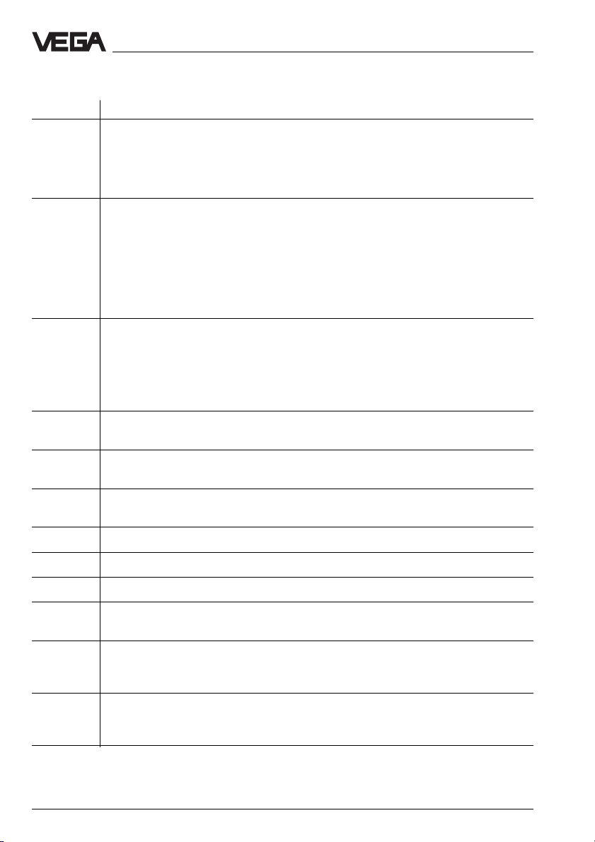
9.5 Error codes
Error code Meaning
Diagnosis
E004 This operation is not supported by the instrument (different software versions).
E014 Possible short-circuit
E015 Possible short-circuit
E016 Empty/full adjustment reversed. The values of the empty adjustment are above
E017 Adjustment span too small. The adjustment values are too close together or are
E021 Span of the scaling values too small or values reversed. The scaling values are
E022 Scaling span too big.
You have tried to activate a function with a newer software version of VEGA
Visual Operating in an instrument with older software version. However, the
instrument cannot support this operation.
Have the software of your instrument updated.
Probable reasons:
- short-circuit
- sensor is defective
Check the connection cable and, if necessary, the sensor.
Also possible
- an incorrect measuring range is adjusted on the capacitive electrode.
Adjust a smaller range.
Probable reasons:
- no sensor connected
- line break
- sensor is defective
Check the connection cable and, if necessary, the sensor.
the values of the full adjustment. Carry out the adjustment again.
identical. Carry out the adjustment again.
too close together or are identical. Please check the scaling.
E027 Actual measured value is less than -10 %.
E28 Actual measured value is more than 110 %.
E031 Same DISBUS address. At least one other instrument with the same DISBUS
E032 Instrument address 0. Instrument address 0 is set on VEGAMET. With this
E034 Instrument error. A considerable error was detected in the instrument (possibly
46 VEGAMET 614
address is connected to the DISBUS. Please check the DISBUS address.
address, VEGAMET does not participate in the DISBUS communication, even if
the DISBUS is wired. If necessary, modify the instrument address.
defective EEPROM). Disconnect voltage and then connect again (cold start). If
the error is not eliminated, please contact your VEGA agency.
Page 47
Diagnosis
Error code Meaning
E035 Instrument error. A serious error was detected in the instrument (check sum
error in EPROM). Disconnect voltage and then connect again (cold start). If the
error is not eliminated, please contact your VEGA agency.
E050 Remote VEGAMET not found. The VEGAMET from which a measured value is
expected cannot be found.
Reasons:
- the remote VEGAMET is not connected
- no VEGAMET with this instrument address connected
- line break (DISBUS)
- short-circuit (DISBUS)
- the remote VEGAMET is defective
- interfered communication (DISBUS)
Also possible:
- failure in the DISBUS transmitter/receiver part of VEGAMET
Please check the instrument address on both VEGAMETs, the connection
cable, the remote VEGAMET and, if necessary, this VEGAMET.
E051 Failure during transmission of measured values via DISBUS. It is not possible
to receive a valid measured value via DISBUS from the remote VEGAMET; the
communication with the remote VEGAMET, however, is okay.
Reason:
- failure on remote VEGAMET
- the input of the remote VEGAMET, which should be transmitted to, is not yet
configured
Please check the remote VEGAMET and, if necessary, its input configuration.
E052 The input number of the VEGAMET from which a measured value is expected
has not yet been assigned.
E053 Span of the sensor characteristics values too small. The sensor characteristics
values are too close together or are identical.
E054 Sensor characteristics values reversed. The min. sensor characteristics value
is higher than the max. sensor characteristics value.
E060 Span of the current output values too small. The values for the current output
are too close together or are identical. Please check the adjustment of the
current output.
E061 Span of the voltage output values too small. The values for the voltage output
are too close together or are identical. Please check the adjustment of the
voltage output.
E063 Incorrect sensor characteristics values. Please check the sensor characteris-
tics values
E102 A reset of the configuration was carried out on this VEGAMET via the key-
board.
VEGAMET 614 47
Page 48

Error code Meaning
Diagnosis
E110 Switching hysteresis too small. The switching points are too close together or
are identical.
E111 Relay switching points swapped. The relay switching points are reversed with
respect to the selected relay mode.
48 VEGAMET 614
Page 49
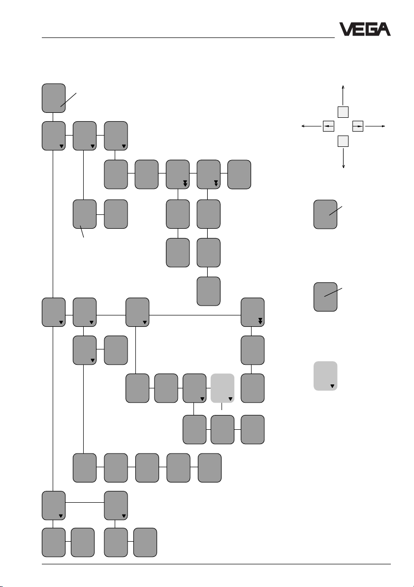
Menu schematic “reduced menu”
10 Menu schematics
10.1 Menu sc hematic “reduced menu”
TAGNo. 1
%
xx,x
Param.
TAGNo. 1
actual
measured
value
Configuration
Add’l
functions
ESC
OK
Adjustment
Password
off
Sensor
type
Hydrostatic
Signal
conditioning
Scaling
TAGname
TAG No. 1
The sensor type can only be
modified, when a "Reset
TAG 1“ has been carried out
first.
Outputs
Integr
ation
time s
0
Current
output 1
4/20mA
Language
English
Volt
output
1
0/10V
TAG 1
to default
Reset
OK ?
Reset
Now !
OK ?
Relay
output
1
Mode
Overfill
protec
Reset
TAG 1
Delete
TAG
1?
Reset
OK ?
Reset
Now !
OK ?
Menu
mode
Reduced
Relay
output
2
like relay output 1
Low
%
0,0
Simulation
Simulation
Now !
OK ?
Simulation
%
xx,x
High
%
100,0
With these keys you
move in the menu field
In white letters
Language
you can see
Eng-
the parameters
lish
which can be
modified with the [+] or [–
] key and saved with the
[OK] key.
Bold print/italic
Param.
is the sensor
TAGNo. 1
or measured
value information which cannot be
modified in this position.
Light grey
Relay
menu items
output
2
are only dis-
played if
necessary
(depending on the
adjustment in other
menu items).
with
medium
Minadjust
at %
0,0
0%
corresponds
Maxadjust
at %
100,0
100%
corresponds
1000
0
without
medium
0%
at
mA
4,000
Decimal
point
888,8
100%
at
mA
20,000
prop.
to
undefined
Unit
– –
VEGAMET 614 49
Page 50

Menu schematic “extended menu”
TAG No. 1
%
xx,x
Param.
TAGNo. 1
Adjustment
with
medium
10.2 Menu schematic “extended menu ”
Unit
0,0%
Current
output
4/20mA
3
Add’l
functions
DK
value
(Er)
81,00
Unit
– –
Relay
outputs
Relay
output
1
prop.
to
Percent
Volt
output
0/10V
Current
at
0%
4,000
Relay
output
2
like relay output 1
Volt
at
0%
0,000
Current
at
100%
20,000
Meas.
value
limitation
negative
values
yes
Signal
conditioning
prop.
to
Percent
Scaling Lin.
curve
linear
100%
0%
corres-
corres-
ponds
ponds
1000
0
without
medium
Outputs
Current
outputs
Current
output
1
Configuration
see following pages
Volt
outputs
Volt
output
1
prop.
to
Percent
Unit
0,0%
Integr
ation
time s
0
Decimal
point
888,8
Density
in
Kg/dm
1,000
prop.
to
undefined
MET
indication
prop.
to
Percent
Volt
at
100%
10,000
Failure
mode
0mA
Failure
mode
Stan
dard
Unit
0,0%
Unit
0,0%
Failure
mode
0V
Current
limitation
on
PC/
DCS
outputs
PC/
DCS
output 1
prop.
to
Percent
Mode
Overfill
protection
Volt
limitation
on
PC/
DCS
output 2
like DCS output1
Unit
0,0%
Low
%
0,0
PC/
DCS
output
High
%
100,0
Minadjust
at %
0,0
Maxadjust
at %
100,0
Adjustment
mA
Offset
correction
Sensor
unpressur’d ?
OK ?
Offset
corr.
Now !
OK ?
0%
at
mA
4,000
100%
at
mA
20,000
50 VEGAMET 614
Page 51

Menu schematic “extended menu”
DIS
outputs
DIS
output
1
prop.
to
Percent
Deviation
%
1,0
DIS
output
2
like DIS output 1
Unit
0,00%
Deviation
per
time
Cycle
time
s
1
DIS
output
3
Failure
mode
off
Number
of
cycles
10
Simulation
Simulation
Now!
OK?
Simulation
%
XX,X
Add’l
functions
Switching
delay
t on
s
0
Special
functions
Reset
Level
Reset
OK ?
Reset
Now!
OK ?
t off
s
0
Manual
corr.
Offset
corr.
Offset
corr.
OK?
Correction
now !
OK ?
Real
value
corr.
Real
value
corr.
OK?
Correction
%
0,0
Correction
Now !
OK ?
Bold print/italic is the sensor or
measured value information
which cannot be modified in
this position.
In white letters you can see the
parameters which can be modified with the [+] or [–] key and
saved with the [OK] key.
Light grey menu items are only
displayed if necessary (depending on the adjustment in
other menu items).
ESC
OK
With these keys you move
Sensor
type
Hydrostatic
Language
English
Current at
100%
20,000
in the menu field
VEGAMET 614 51
Page 52

Menu schematic “extended menu”
TAG No. 1
%
xx,x
Param.
TAGNo. 1
see previous
pages
Measured value
indication
Config
inputs
Config
meas.
loop
TAG 1
Level
Configuration
Config
outputs
Config
current
output
Curr.1
to
TAG No. 1
Config
Volt
output
Volt1
to
TAG No. 1
Add’l
functions
see following
pages
Config
relay
output
Operating
relay
Rel. 1
to
TAG No. 1
Fail
safe
relay
Relay
Standard
Rel. 1
Standard
Config
PC/
DCS
output
PC/
DCS
meas.
values
DCS 1
to
TAG No. 1
Rel. 2
to
TAG No. 1
PC/DCS
relay
status
off
DCS 2
to
----
Rel. 1
Standard
Config
VEGADIS
DIS 1
to
TAG No. 1
DCS 3
to
----
DIS 2
to
----
DIS 3
to
----
Application
Level
1) 1) 1) 1)
1)
Input
no. 1
Input
Chan-
from
nel no.
local
Met
S1
Sensor
type
Hydrostatic
The parameters in these menu items can
only be modified, when a "Reset to
single measurement“ has been carried
out first.
Input
undefined
Mode
Standard
Sensor
characteristics
Min.
meas.
range
0,00
Option
no
option
Max.
meas.
range
1,00
Sensor
coordination
Position A
Input1
Min.
sensor
value
4,000
TAGname
TAG No. 1
Max.
sensor
value
20,000
Fault
signal
on
52 VEGAMET 614
Page 53

Menu schematic “extended menu”
Bold print/italic is the sensor or
measured value information
which cannot be modified in
this position.
In white letters you can see the
parameters which can be modified with the [+] or [–] key and
saved with the [OK] key.
Light grey menu items are only
displayed if necessary (depending on the adjustment in
other menu items).
ESC
OK
With these keys you move
Sensor
type
Hydrostatic
Language
English
Current at
100%
20,000
in the menu field
VEGAMET 614 53
Page 54
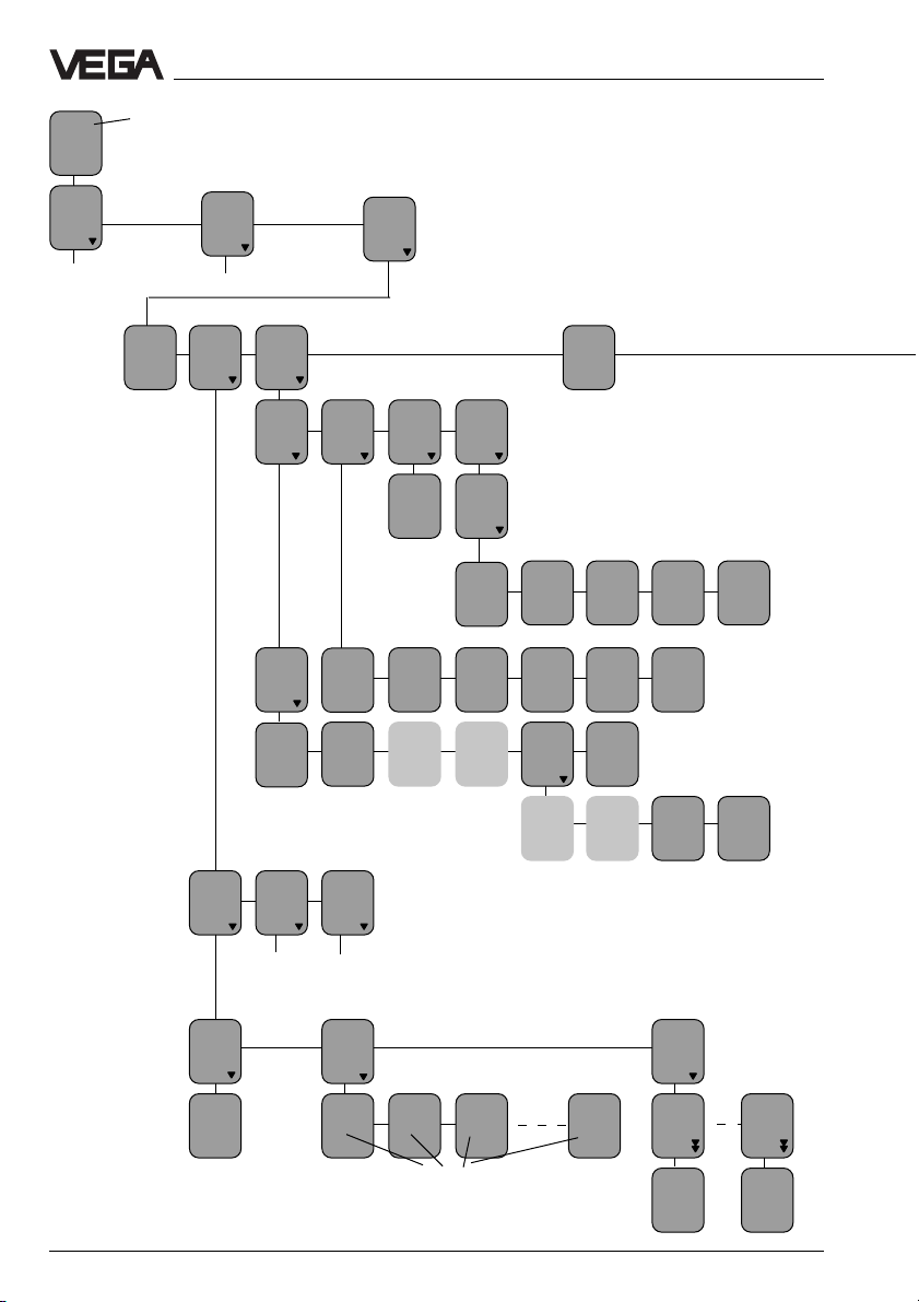
Menu schematic “extended menu”
TAG No. 1
%
xx,x
Param.
TAGNo. 1
see previous
pages
Measured value indication
Configuration
see previous pages
Password
off
Edit
lin.
curve
Lin.
curve1
Add’l
functions
Info Lang-
xxxx
S1
Meas.
loop
info
TAG 1
TAG No. 1
Minadjust
at %
0,0
Instr.
addr.
Input
undefined
1
Input
info
Input 1 Type
Sensor
type
hydrostatic
Lin.
curve2
VEGAMET
info
MET614
Input
from
local
MET
Lin.
curve3
Program
info
Program
info
xxxxxx
Serial
number
xxxx
Channel no.
Minadjust
bar
0,000
Softw.
vers.
V1.13
06
Sensor
characteristics
Min.
meas.
range
0,00
uage
English
Max adjust
at %
100,0
Softw.
date
47/97
Act.
sensor
value
xx,xxx
Max.
meas.
range
1,00
Maxadjust
bar
1,000
Param.
vers.
5
Min.
sensor
value
4,000
Parameter
Level
Max.
sensor
value
20,000
like LIN-curve 1
Add
lin.
point
x %
0,0
y V%
0,0
Edit
lin.
curve 1
x
0 %
0,0
y 0 V%
0,0
x 1 %
y 1 V%
100,0
x 2 %
100,0
100,0
y 2 V%
100,0
Index marker number (0…32)
x32 %
100,0
y32 V%
100,0
Delete
lin.
point
x 0,0
y 0,0
delete
Delete
now?
x100,0
y100,0
delete
Delete
now?
54 VEGAMET 614
Page 55

Menu schematic “extended menu”
Reset
VEGAMET
Reset
configuration
TAG 1
to default
Reset
OK?
Reset
Now!
OK?
Service
to
single
meas.
Reset
TAG 1
Delete
TAG 1 ?
Reset
OK?
Reset
Now!
OK?
Reset
sensor
values
Reset
input
1
Reset
OK?
Reset
Now!
OK?
Menu
mode
Extended
Reset
lin.curves
Reset
lin.
curve1
Reset
OK?
Reset
Now!
OK?
Reset
lin.
curve2
Reset
OK?
Reset
Now!
OK?
Reset
lin.
curve3
Reset
OK?
Reset
Now!
OK?
Reset
all
curves
Delete
all
curves?
Reset
OK?
Reset
Now!
OK?
Sensor
type
Hydrostatic
Bold print/italic is the sensor or
measured value information
which cannot be modified in
this position.
In white letters you can see the
parameters which can be modified with the [+] or [–] key and
saved with the [OK] key.
Light grey menu items are only
displayed if necessary (depending on the adjustment in
other menu items).
ESC
OK
With these keys you move
Language
English
Current at
100%
20,000
in the menu field
VEGAMET 614 55
Page 56

VEGA Grieshaber KG
Am Hohenstein 113
D-77761 Schiltach
Phone (07836) 50-0
Fax (07836) 50-201
E-Mail info@de.vega.com
www.vega.com
Safety information
Please read this manual carefully, and also take
note of country-specific installation standards
(e.g. the VDE regulations in Germany) as well
as all prevailing safety regulations and accident prevention rules.
For safety and warranty reasons, any internal
work on the instruments, apart from that involved in normal installation and electrical connection, must be carried out only by qualified
VEGA personnel.
Note Ex area
Please note the attached safety instructions
containing important information on installation
and operation in Ex areas.
These safety instructions are part of the operating instructions and come with the Ex approved instruments.
ISO 9001
All statements concerning scope of delivery, application, practical
use and operating conditions of the sensors and processing systems correspond to the latest information at the time of printing.
Technical data subject to alterations
2.21 861 / March 2001
 Loading...