

Page 1
in
out
Operating Instructions
VEGAMET 601, 602
12 43
100
%
Level and Pressure
50
0
on
VEGAMET 601
56 78
9 1011121314
out
in
Page 2

Safety information
Safety information
Please read this manual carefully, and also take
note of country-specific installation standards
(e.g. the VDE regulations in Germany) as well
as prevailing safety regulations and accident
prevention rules.
For safety and warranty reasons, any internal
work on the instruments, apart from that involved in normal installation and electrical connection, must be carried out only by qualified
VEGA personnel.
2 VEGAMET 601, 602
Note Ex area
Please note the attached safety instructions
containing important information on installation
and operation in Ex areas.
These safety instructions are part of the
operating instructions and come with the Ex
approved instruments.
Page 3

Contents
Contents
Safety information ........................................................................ 2
Note Ex area ................................................................................ 2
1 Product description
1.1 Function and configuration .................................................. 4
1.2 Approvals ............................................................................. 4
1.3 Types and versions ............................................................. 5
1.4 Technical data ....................................................................... 6
1.5 Dimensions ........................................................................... 9
2 Mounting and installation instructions .............................. 10
3 Electrical connection
3.1 Connection instructions ..................................................... 12
3.2 Connection instructions for approved applications ........ 12
3.3 Wiring plans ........................................................................ 13
4Setup
4.1 Indicating and adjustment elements ................................ 14
4.2 Setup sequence ................................................................. 15
4.3 Adjustment .......................................................................... 15
5 Diagnostics
5.1 Maintenance ....................................................................... 18
5.2 Repair .................................................................................. 18
5.3 Failure rectification ............................................................. 18
VEGAMET 601, 602 3
Page 4
1 Product description
1.1 Function and configuration
Product description
VEGAMET 601 and 602 signal conditioning
instruments are modulare units with plug-in
sockets suitable for carrier rail mounting
(DIN 46 277). Together with the respective
sensors they are used for continuous level
measurement.
The evaluation results are made available as
a current output 0/4 … 20 mA and a voltage
output 0 … 10 V. The instruments are
equipped with an adjustable integration time,
and in addition VEGAMET 602 Ex has a fault
monitoring.
Function
The measuring data of the sensor are
outputted as level-proportional current and
voltage signals. The adjustment (empty and
full adjustment) can be done very easily via
two potentiometers.
Fault monitoring on VEGAMET 602
The integrated fault monitoring on VEGAMET
602 detects shortcircuit and line break of the
measuring cable. A failure LED lights in case
of failure and a failure relay deenergises.
Configuration
12 34
100
%
p
p
VEGAMET …
on
VEGAMET 601
56 78
91011121314
4 ... 20 mA
50
0
0 ... 10 V
1.2 Approvals
If measuring systems are installed according
to the following approvals, the respective
official documents must be consulted and
their regulations followed. The documents are
supplied with the respective measuring system.
WHG approval
VEGAMET 602 Ex signal conditioning instrument together with capacitive electrodes or
pressure transmitters as part of an overfill
protection system acc. to WHG.
To configure a measuring system, you need
a VEGAMET … signal conditioning instrument
and a sensor with analogue transmission of
measured values, e.g.
- capacitive electrodes or
Ex approval
For measuring system in hazardous areas,
certificate acc. to CENELEC.
VEGAMET 602 Ex signal conditioning instrument
- hydrostatic pressure transmitters or
- process pressure transmitters.
CE approval
see "Technical data".
4 VEGAMET 601, 602
Page 5
Product description
1.3 Types and versions
VEGAMET 601
Signal conditioning instrument for continuous level or process pressure measurement
Adjustment via two potentiometers
with adjustable integration time
Input: 1 capacitive electrode or
1 hydrostatic pressure transmitter or
1 process pressure transmitter
Outputs: 1 current output 0/4 … 20 mA
1 voltage output 0 … 10 V
Application: level measurement, process pressure meas-
urement
VEGAMET 602 Ex
Signal conditioning instrument for continuous level or process pressure measurement
Fault monitoring
Adjustment via two potentiometers
with adjustable integration time
Input: 1 capacitive electrode or
1 hydrostatic pressure transmitter or
1 process pressure transmitter
Outputs: 1 current output 0/4 … 20 mA
1 voltage output 0 … 10 V
1 fail-safe relay
Approvals: [EEx ia] IIC, [EEx ia] IIB,
as part of an overfill protection system acc.
to WHG
Application: level measurement, process pressure meas-
urement
Level
100
%
50
0
on
0 20 mA
10 V
Continuous measurement VEGAMET
601
Level
100
%
50
0
on
Ex area
0 20 mA
Non-Ex area
10 V
Continuous measurement VEGAMET
602 Ex
VEGAMET 601, 602 5
Page 6

Product description
1.4 Technical data
General data
Power supply
Operating voltage 20 … 250 V AC, 50/60 Hz
Power consumption max. 3 W (3 … 18 VA)
Fuse T 1 A, 250 V
Meas. data input
Number 1 current input
Type of input active two-wire input analogue (sensor powered
Range 4 … 20 mA
Sensor capacitive electrodes
Sensor power supply
- VEGAMET 601 24 V DC
- VEGAMET 602 Ex approx. 15 … 18 V DC
Current limitation at 24 mA, permanently shortcircuit proof
Connection cable 2-wire (standard cable)
Resistance per conductor
- VEGAMET 601 max. 250 Ohm
- VEGAMET 602 Ex max. 35 Ohm
20 … 72 V DC
emergency power supply with curve shape extremely deviating from sine: U
(rectangle)
= 125 V AC
max.
by signal conditioning instrument)
hydrostatic pressure transmitters
process pressure transmitters
Electrical connection
Screw terminals max. 1.5 mm
2
Electrical protective measures
Protection
- instrument IP 30
- plug-in socket IP 20
Protection class II
Overvoltage category II
Mechanical data
Series module unit with plug-in socket, incl. transparent
cover, cover for the special terminals, coded
pin, two bonding jumpers
Mounting carrier rail mounting acc. to DIN 46 277, Bl. 3
Dimensions unassembled W = 36 mm, H = 118.5 mm, D = 134 mm
Weight approx. 170 g
6 VEGAMET 601, 602
Page 7

Product description
Ambient conditions
Permissible ambient temperature -20°C … +60°C
Storage and transport temperature -40°C … +70°C
Current output
Number 1 output
Function analogue output of the evaluated data
Range 0/4 … 20 mA
Load max. 500 Ohm
Resolution 0.05 % of range
Linearity error 0.05 % of range
Temperature error 0.08 %/10 K of range
Voltage output
Number 1 output
Function analogue output of the evaluated data
Range 0 … 10 V
Current max. 1 mA
Resolution 0.05 % of range
Linearity error 0.05 % of range
Temperature error 0.08 %/10 K of range
Relay output (only with VEGAMET 602)
Number 1 output
Contact 1 floating spdt each
AgNi and hard gold plated
Turn-on voltage min. 10 mV DC
max. 250 V AC, 60 V DC
Switching current min. 10 µA DC
max. 3 A AC, 1 A DC
Breaking capacitance max. 500 VA, 54 W
Indicating elements
LED in front plate green on: operating voltage on
red: fault signal (only on VEGAMET 602)
Analogue indication 11 segments, 0 % … 100 %
Functions
Integration time 0 … 20 sec.
Adjustable current output 0 … 20 mA/4 … 20 mA
Adjustment elements
On front plate two potentiometers for adjustment of the
empty and full adjustment
On top, laterally DIL switch
- adjustment of the current output
0 … 20 mA/4 … 20 mA
- integration time
VEGAMET 601, 602 7
Page 8

Product description
Electrical separation measures
Reliable separation acc. to VDE 0106,
part 1 between the potentials
- reference voltage 250 V
- isolation resistance 3 kV
Potentials VEGAMET 601
- potential 1 supply voltage
- potential 2
(common minus potenial) meas. data input (sensor connection),
current output, voltage output
Potential VEGAMET 602
- potential 1 supply voltage
- potential 2 meas. data input (sensor connection)
- potential 3
(common minus potenial) current output, voltage
- potential 4 fail-safe relays, contacts
CE conformity
VEGAMET signal conditioning instruments meet the protective regulations of EMC
(89/336/EWG) and NSR (73/23/EWG). Conformity has been judged acc. to the following
standards:
EMC Emission EN 50 081 - 1: 1992
Susceptibility EN 50 082 - 2: 1995
NSR EN 61 010 - 1: 1993
Ex technical data
Meas. data input (intrinsically safe signal circuit)
Classification [EEx ia] IIC or [EEx ia] IIB
Max. values
- voltage UO - 20 V
- current IO - 125 mA
- power PO - 624 mW
Characteristics linear
Effective inner inductance L
Effective inner capacitance C
i
i
negligible
negligible
EEx ia IIC EEx ia IIB EEx ib IIC EEx ib IIB
Max. permissible outer
inductance LO (mH) 0.5 1 1.5 2 2 9
Max. permissible outer
capacitance CO (nF) 97 78 68 486 200 1000
The intrinsically safe circuits are reliably separated from the non intrinsically safe circuits up
to a peak voltage of 375 V.
The max. voltage on the non intrinsically safe circuits should not exceed 250 V
failure.
8 VEGAMET 601, 602
in case of
eff
Page 9

Product description
1.5 Dimensions
Transparent cover
134
Carrier rail 35 x 7.5 or
35 x 15 acc. to EN 50 022
54,5
12 34
118,5
on
56 78
9 1011121314
36
VEGAMET 601, 602 9
Page 10

2 Mounting and installation instructions
Mounting and installation instructions
Mounting
Each series 600 signal conditioning instrument consists of a plug-in socket for carrier
rail mounting DIN 46 277 and a module unit.
The supply voltage can be connected to
terminals 9 and 10.
For neighbouring series 600 signal conditioning instruments it is possible to continue
the connection L1 and N directly via the supplied plug-in jumpers.
The same is valid for the connection of VEGAMET voltage output 0 … 10 V to VEGASEL
voltage input 0 … 10 V, terminals 7 and 8).
Note!
It is not allowed to use the jumpers for single
instruments or at the respective end of an
instrument row. If this instruction is not observed, there is the danger of contacting the
operating voltage or causing a short-circuit.
As a rule, the signal conditioning instrument
must be mounted outside the hazardous
area or special Ex protective measures must
be taken.
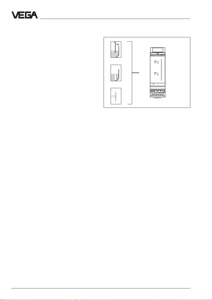
Transparent cover
To protect the instrument against unauthorised or inadvertent use, the front plate of
VEGAMET can be provided with a sealable
transparent cover after setup. To remove the
transparent cover see the following figure.
10 VEGAMET 601, 602
Page 11

Mounting and installation instructions
Coding
To avoid mixing up the various signal conditioning instruments, the plug-in socket is
provided with pins and the signal conditioning instrument with appropriate gaps
(mechanical coding).
Instrument coding ensures (with differently
positioned coded pins) that the various signal conditioning instruments are not inadvertently swapped.
An Ex coding with fixed coded pin ensures
that non-Ex and Ex instruments are not interchanged.
The coding is part of the explosion protection: on VEGAMET 602 Ex the supplied
coded pins (instrument coded pin and Ex
coded pin) must be inserted by the operator
acc. to the table below.
Instrument Ex
coding coding
VEGAMET 601 1 ––
VEGAMET 602 Ex 1 A
Separating wall
(must be always plugged
with Ex instruments)
Ex coding
Instrument coding
VEGAMET 601, 602
Direct supply for voltage
output 0 … 10 V
Direct connection for supply
voltage
12 4
3
A o
VEGA
B o
C o
1 o
2 o
3 o
o
0…10 V
o
o
DISBUS
7 o
8 o
9 o
o
N
o
L1
o
56 78
91011121314
VEGAMET 601, 602 11
Page 12

3 Electrical connection
Electrical connection
3.1 Connection instructions
The following wiring plans are valid for standard as well as Ex versions of the signal conditioning instruments. Please observe the
following instructions:
- the relay contact of VEGAMET 602 Ex is
shown in a de-energised condition
- if strong electromagnetic interferences are
expected, we recommend the use of
screened signal cables
- the screening must be earthed only on one
side (sensor side)
- in case of overvoltages, we recommend
the use of VEGA overvoltage arresters
- the connection must be made acc. to the
respective national installation standards
(e.g. in Germany acc. to the VDE regulations).
3.2 Connection instructions for approved applications
The following applications require the use of
certified instruments:
- in hazardous areas (if necessary, observe
special national regulations)
- as part of an overfill protection system acc.
to WHG
- in the shipbuilding industry
- in pressurised vessels.
For these applications, the respective official
documents (test reports, test certificates,
general type approval, type approval certificate and conformity certificates) as well as
the valid installation and operating regulations
must be noted. The official documents are
supplied with the respective instrument.
In Ex applications, the voltage supply of the
sensor must only be made via an intrinsically
safe circuit. These are the possibilities:
- VEGAMET series 600 signal conditioning
instrument in Ex version
- not certified VEGAMET series 600 signal
conditioning instrument with VEGA safety
barrier type 145
The official documents of these additional
instruments must also be noted.
12 VEGAMET 601, 602
Page 13

Electrical connection
3.3 Wiring plans
–
+
12
+
12
Sensor
–
VEGAMET 601
VEGAMET 602 Ex
Current output 0/4 … 20 mA
111213 14
–
10 V
+–
78
Voltage output 0 … 10 V
Fail safe relay
20 mA
+–
56
910
+
L1
10 V 20 mA
+–
78
–
NL1N
+–
56
910
+
Supply voltage
Extension example
1st instrument = VEGAMET 601 or 602
2nd up to max. 10th instrument = VEGASEL 643, each wired to the passive voltage input
(parallel connection)
Sensor
–
+
12
active
VEGAMET
–
10 V
–
+
87
+
12
passive
–
10 V
VEGASEL
+
43
–
+
87
–
+
12
passive
VEGASEL
10 V
–
+
43
–
+
87
1st instrument 2nd instrument ................. max. ...........10th instrument
Acc. to the above extension example, it is
possible to control several signal conditioning
Each configuration of this kind can be ex-
tended each up to 10 instruments.
instruments with one sensor and to detect
different levels.
VEGAMET 601, 602 13
Page 14

4 Setup
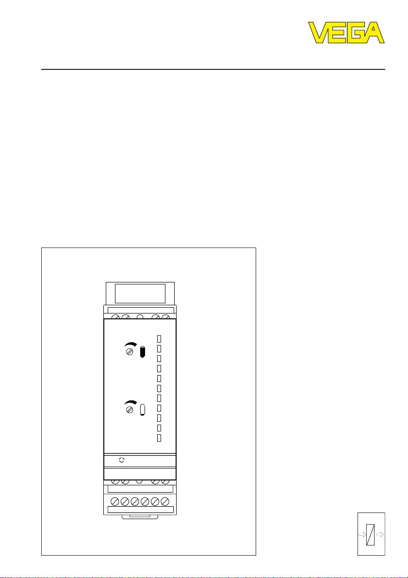
4.1 Indicating and adjustment elements
Setup
1
2
3
Top view
12 43
on
VEGAMET 601
56 78
9 1011121314
100
50
0
4
5
%
1
6 6
12 43
100
%
50
4
5
2
0
9
3
7 7
8
10
11
12
!
on
VEGAMET 602EX
56 78
91011121314
1 Potentiometer full adjustment
2 Potentiometer empty adjustment
3 LED supply voltage
4 Separating wall
5 Terminals input
6 Analogue display with 11 segments 0 % … 100 %
7 Terminals outputs
8 Terminals supply voltage
9 LED fault signal
10 Bar code, serial number
11 DIL switch block
12 Screws
13 Ventilation opening
14 Transparent cover
8
13
14
14 VEGAMET 601, 602
Page 15

Setup
Potentiometer
With the potentiometers (1 and 2) you can
carry out the max. and min. adjustment.
Control lamps
Green (3)
- supply voltage available
- ready for operation
Red (9)
- failure indication
Analogue display (6)
Indication of the actual level relating to the
adjustment 0 % … 100 %. Resolution in 11
segments.
DIL switch (11)
On top, to the side - covered by the plug-in
socket when the signal conditioning instrument is mounted.
Description of the DIL switch positions
12
t sec
6
off
2
0..20mA
4..
With the upper three DIL switches you can
set an integration time. If all three are set to
position "off", the integration time is zero seconds. With switch "2" two seconds are set,
with switch "6" six seconds are set, etc. If
several switches are set to "on", the time
intervals will be summed up. It is therefore
possible to set 2, 6, 8,12, 18 or 20 seconds
as integration time.
With the fourth DIL switch you choose if you
want to have a 4 … 20 mA or a 0 … 20 mA
current output.
4.2 Setup sequence
The following list gives you a short descrip-
tion of the setup steps
- mount the plug-in socket
- wire the plug-in socket acc. to your control
requirements
- cover the input terminals with the separating wall (4)
- set the range of the current output on the
DIL switch (11)
- set the integration time on the DIL switch
(11) to "off"
- now mount the module unit into the plug-in
socket
- switch on the power supply, the green LED
(3) lights
- carry out the adjustment acc. to "Section
4.3"
- if an integration time is necessary, the instrument must be removed again and the
respective setting must be made on the
DIL switch.
4.3 Adjustment
The adjustment of the empty and full levels is
made via two spindle potentiometers. For the
adjustment procedure, it is useful to connect
a voltmeter to the voltage output 0 … 10 V.
This means:
- empty adjustment, vessel empty corresponds to 0.0 Volt or level 0 %
- full adjustment, vessel full corresponds to
10.0 Volt or level 100 %
Note the following adjustment examples. As a
rule, the potentiometer 1 must first be turned
approx. 22 revolutions clockwise before the
empty and full adjustment is carried out.
As an additional aid to adjustment, the lowest
segment of the analogue display flashes at
0.0 V and the highest at 10.0 V.
VEGAMET 601, 602 15
Page 16

Setup
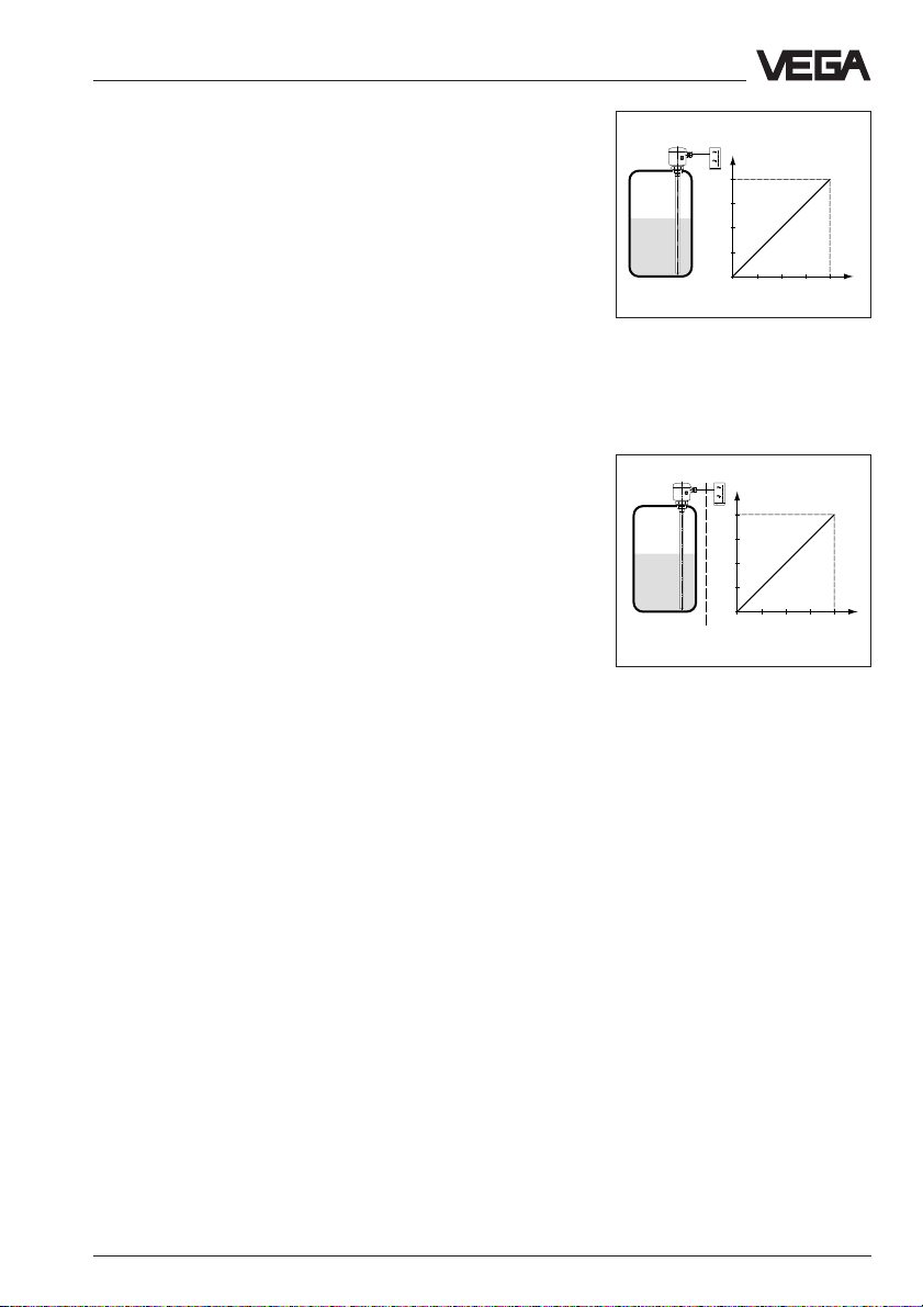
Adjustment example 1
The vessel can be emptied to min. level and
filled to max. level.
Sensor:
- vertically mounted capacitive measuring
probe
- hydrostatic pressure transmitter
- process pressure transmitter
Level
100 %
Capacitive
electrodes
100 %
0 %
Hydrostatic pressure
transmitter
Process pressure
transmitter
Procedure:
• First of all, turn the potentiometer full adjustment (1) approx. 22 revolutions clockwise.
• Fill the vessel to the requested minimum
level.
• Set with the potentiometer empty adjustment (2) the display of the connected
measuring instrument to 0.0 V, this corresponds to 0 %.
• Fill the vessel to the requested max. level.
• Set with the potentiometer full adjustment
(1) the display of the connected measuring
instrument to 10.0 V by turning anticlockwise, this corresponds to 100 %.
• The signal conditioning instrument is adjusted and ready for operation
Please cover with the transparent cover
(14).
0 %
0/4
0
16 VEGAMET 601, 602
20 mA
10 V
Page 17

Setup
Adjustment example 2
The vessel cannot be emptied to min. level
and also cannot be filled to max. level.
Sensor:
- vertically installed capacitive measuring
probe
- hydrostatic pressure transmitter
- process pressure transmitter
Level
100 %
80 %
Capacitive
electrodes
80 %
20 %
Hydrostatic pressure
transmitters
Process pressure
transmitters
Procedure
• First of all, turn the potentiometer full adjustment (1) clockwise by approx. 22 revolutions.
• Empty the vessel to the lowest possible
level and sound the contents (e.g. 20 %).
• Set with the potentiometer empty adjustment (2) the display of the connected
measuring instrument to 0.0 V.
• Fill the vessel to the highest possible level
and sound the contents (e.g. 80 %).
• Calculate the value to be adjusted for the
potentiometer full adjustment (1).
Example: 80 % (filled) – 20 % (emptied) =
60 %.
• Set with the potentiometer full adjustment
(1) the display of the connected measuring
instrument to 6.0 V by turning anticlockwise.
• Now set with the potentiometer empty
adjustment (2) the actual level (example
80 %).
• The signal conditioning instrument is adjusted and ready for operation.
Please cover with the transparent cover
(14).
20 %
0 %
0/4
0
VEGAMET 601, 602 17
20 mA
10 V
Page 18

5 Diagnostics
Diagnostics
5.1 Maintenance
The instrument is maintenance-free.
In case of a defect, please return the affected
instrument with a short description of the
error to our repair department.
Failures are brief instrument malfunctions
5.2 Repair
To correct possible defects, the instrument
must be opened. For safety and warranty
reasons, any internal work on the instruments, apart from that involved in normal
installation and electrical connection, must be
which are caused by wrong adjustment or
defects in the sensor or the connection cables.
Failures, their possible causes and their
elimination are listed under "5.3 Failure rectification".
carried out only by qualified VEGA personnel.
5.3 Failure rectification
Failure Rectification/Measure
Instrument does not
function/Green
operating control
lamp extinguishes Check the supply voltage and the mains connections by noting the
Function of VEGA- Check the sensor inputs for the following causes of failures:
MET 601 is wrong - shortcircuit on the input
or failed - sensor not correctly connected, i.e. polarity reversed
Red failure LED - supply voltage too low
of VEGAMET 602
lights Check if the sensor is connected correctly.
"Wiring instructions". If the instrument still does not function, call our
service department.
- sensor cable interrupted
- failures in the sensor, effecting a current change below 2 mA or
above 23 mA, cause a fault signal in VEGAMET.
15 … 18 V
(24 V with VEGAMET 601)
V
VEGAMET
Measure the current
on the connection cable
leading to the sensor.
4 … 20 mA
+
–
mA
12 43
With Ex systems, make sure that the Ex protection is not
degraded by the measuring instruments.
18 VEGAMET 601, 602
Page 19

Diagnostics
Failure Rectification/Measure
Function of VEGAMET 601 is wrong
or failed
Red failure LED
of VEGAMET 602
lights a.Current value < 2 mA
- Check the supply voltage on the connection cable leading to the
sensor. The voltage should be at least 17 V.
Should you measure a value below 17 V, this indicates defect in the
signal conditioning instrument. In this case, send the instrument for
repair to VEGA.
- If at least 17 V are present, separate the signal conditioning instrument from the connection cable and connect a resistor of 2.2 kOhm
to the sensor input of the signal conditioning instrument.
If the failure lamp continues to light, the signal conditioning instrument
is defective. In this case, send the instrument for repair to VEGA.
- Should the failure lamp extinguish, connect the signal conditioning
instrument again. Separate the sensor from the connection cable and
connect instead a resistor of 2.2 kOhm.
- If the failure lamp continues to light, probably the connection cable is
interrupted. Check the connection cable leading to the sensor.
- If the failure lamp extinguishes, the sensor is defective. Check the
connected sensor.
b. Current value > 23 mA
- Check all connections and the connection cable leading to the sensor.
- Should the red failure lamp continue to light, separate the sensor
from the connection cable and connect instead a resistor of
2.2 kOhm.
If the failure lamp extinguishes, the sensor is defective. Check the
connected sensor.
- Should the failure lamp continue to light, reconnect the sensor. Separate the signal conditioning instrument from the connection cable and
connect to its sensor input a resistor of 2.2 kOhm.
- Should the failure lamp continue to light, the signal conditioning instrument is defective. In this case, return the instrument for repair to
VEGA.
- If the failure lamp extinguishes, there is probably a shortcircuit in the
connection cable. Check the connection cable leading to the sensor.
VEGAMET 601, 602 19
Page 20

VEGA Grieshaber KG
Am Hohenstein 113
77761 Schiltach/Germany
Phone +49 (0) 7836 50-0
Fax +49 (0) 7836 50-201
E-Mail info@de.vega.com
www.vega.com
ISO 9001
All statements concerning scope of delivery, application, practical
use and operating conditions of the sensors and processing systems correspond to the latest information at the time of printing.
Technical data subject to alterations
19944-EN-020101
 Loading...