

Page 1
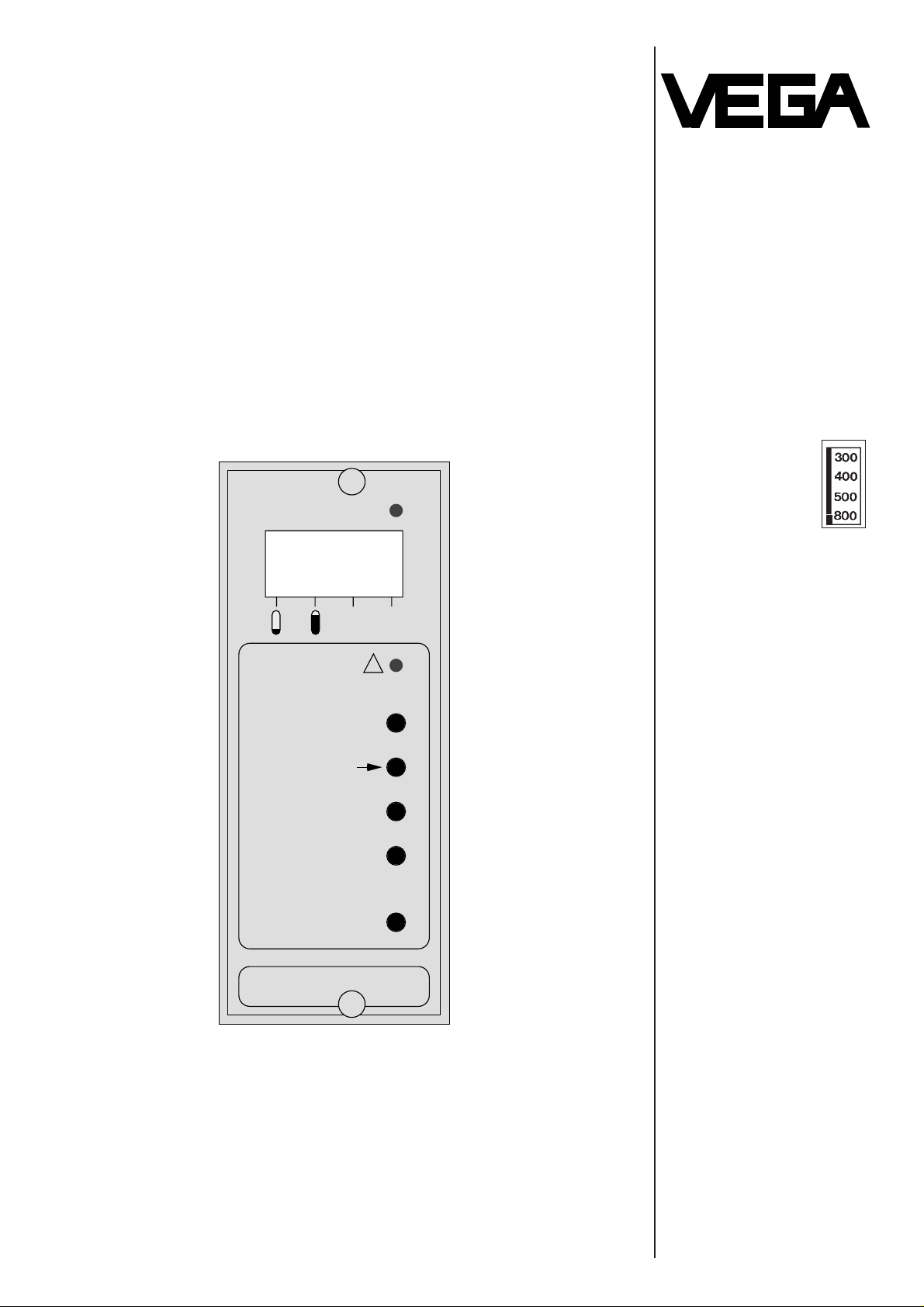
VEGAMET 407 Z
TIB • Technical Information • Operating Instructions
Signal conditioning
instrument for
continuous level
measurement
Signal conditioning instrument with plastic housing
of series 400
Supply for
- one pressure sensor
or
- one capacitive
measuring electrode
Conditioning of analog
transmitted measuring
data
VEGA Grieshaber KG
Am Hohenstein 113
Postfach 11 42
D-77757 Schiltach
Phone 0 78 36/50-0
MOD
+
-
STO
!
t
SIM
VEGAMET
407 Z
50.0
%
Page 2

Contents
Contents of the instruction manual
The described module must only be inserted and
operated as described in this TIB. Please note that
other action can cause damage or destruction for
which VEGA does not take responsibility.
The measuring systems certified as overfill
protection acc. to WHG and as overfill protection
acc. to the regulation for combustible liquids (VbF)
are listed on page 6 and 7.
Security information
Introduction Contents of the instruction manual .....................................................2
Security information ............................................................................2
Product description .............................................................................3
Technical Information Configuration of a signal conditioning instrument ...............................3
Configuration of a measuring system .................................................3
Technical data ....................................................................................4
Galvanical separation .........................................................................5
Dimensional drawing ..........................................................................5
Approvals ............................................................................................6
Mounting instructions ..........................................................................8
Electrical connection ...........................................................................8
Operating surface Indication and operating elements ......................................................9
Operation...........................................................................................10
Set-up ...............................................................................................10
Parameter adjustment Empty / full adjustment ..................................................................11
Integration time .................................................................................12
Simulation .........................................................................................12
Password ..........................................................................................13
Alarm information Alarm signal ......................................................................................13
Fault diagnosis .................................................................................14
The
Technical Information / Operating instruc-
tions is called TIB. It contains all necessary infor-
mation for correct:
- installation
- connection
- set-up
- parameter adjustment
of the signal conditioning instrument
VEGAMET 407 Z.
If you feel that any points in this data sheet are not
adequately covered our technical sales or service
departments will be pleased to assist.
Additional copies of this data sheet are freely
available and are automatically supplied with
quotations and purchases product.
Page 3
Introduction
Product description
The signal conditioning instrument VEGAMET
407 Z is used for manifold applications for
continuous level measurement.
VEGAMET 407 Z is integrated in a series 400
plastic housing.
A sensor (pressure transmitter or capacitive measuring electrode) can be connected via a two-core
line to the signal conditioning instrument. This line
is responsible for the power supply from the signal
conditioning instrument to the sensor. The measuring currents are transmitted analog from the sensor
to the signal conditioning instrument and evaluated.
The signal conditioning instrument can be
calibrated and adapted to the measurement by the
user via parameter adjustment.
These adjustments are made without additional
facilities and tools via a 5-button keyboard
integrated on the front panel.
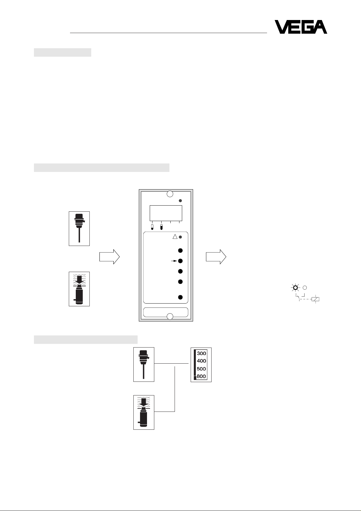
Configuration of a signal conditioning instrument
MOD
+
-
STO
!
t
SIM
VEGAMET
407 Z
or
4-digit LC-display
current output 0/4 … 20 mA
voltage output 0 … 5 V
voltage output 0 … 10 V
Fail safe relay
Alarm LED
capacitive measuring
electrode
pressure transmitter
Input Signal conditioning instrument Outputs:
50.0
%
Capacitive measuring
electrode with oscillator
or
Pressure transmitter
with oscillator
Optional auxiliary instruments e.g.: - Overvoltage arresters
- Indicating meters VEGADIS 171 (connection 0 … 20 mA)
- Auxiliary level switch VEGASEL ……
- Safety barrier type 145
Configuration of a measuring system
Signal conditioning instrument
VEGAMET 407 Z mounted into
plastic housing of series 400
Page 4

Technical Information
Technical data
Power supply Operating voltage value tolerance frequency
Standard 230 V AC +10 % –15 % 50 / 60 Hz
Options 110 V AC
130 V AC +15 % –10 % 50 / 60 Hz
240 V AC
24 V AC
42 V AC +15 % –10 % 50 / 60 Hz
48 V AC
16 … 60 V DC
Power consumption approx. 6 VA or 4 W
Measuring data Supply voltage for capacitive
measuring electrode or
pressure transmitter 24 V (max. 26 V) short-circuit proof, galvanically isolated
Data transmission analog
Connection cable 2-core, unscreened (standard line)
Resistance per conductor max. 200 Ω
Valid measured values 2 … 22 mA
Fault signal at < 2 mA; > 22 mA
Min. measuring distance 300 µA
Indication LC-display 4-digit
Current output Range 0 … 20 mA or 4 … 20 mA
Load max. 750
Ω
Galvanical separation to power supply unit and input
Resolution 0,05 % of range
Linearity error 0,05 % of range
Temperature error 0,06 % / 10 K of sensor
Voltage output 1 Range 0 … 10 V, max. 1 mA
Galvanical separation to power supply unit and to input
Resolution 0,05 % of range
Linearity error 0,1 % of range
Temperature error 0,06 % / 10 K of sensor
Voltage output 2 Range 0 … 5 V, max. 1 mA
Galvanical separation to power supply unit and to input
Resolution 0,05 % of range
Linearity error 0,1 % of range
Temperature error 0,06 % / 10 K of sensor
Fail safe relay Relay data:
1 spdt floating
Contact material Ag CdO and Au plated
min. turn-on voltage 10 mV
switching circuit 10 µA
AC DC
max. turn-on voltage U = 250 V U = 60 V
switching circuit I = 2 A I = 1 A
max. breaking capacity S = 125 VA P = 54 W
Operating Permissible operating temperat. –20°C … +60°C
conditions Storage and transport temperat. –20°C … +70°C
Electrical Protection IP 40
protective measures Protection class II
Mechanical Series Panel mounting, housing plastic ABS light grey
data Dimensions W = 53 mm, H = 127 mm, D = 143 mm
Weight approx. 700 g
Page 5
Technical Information
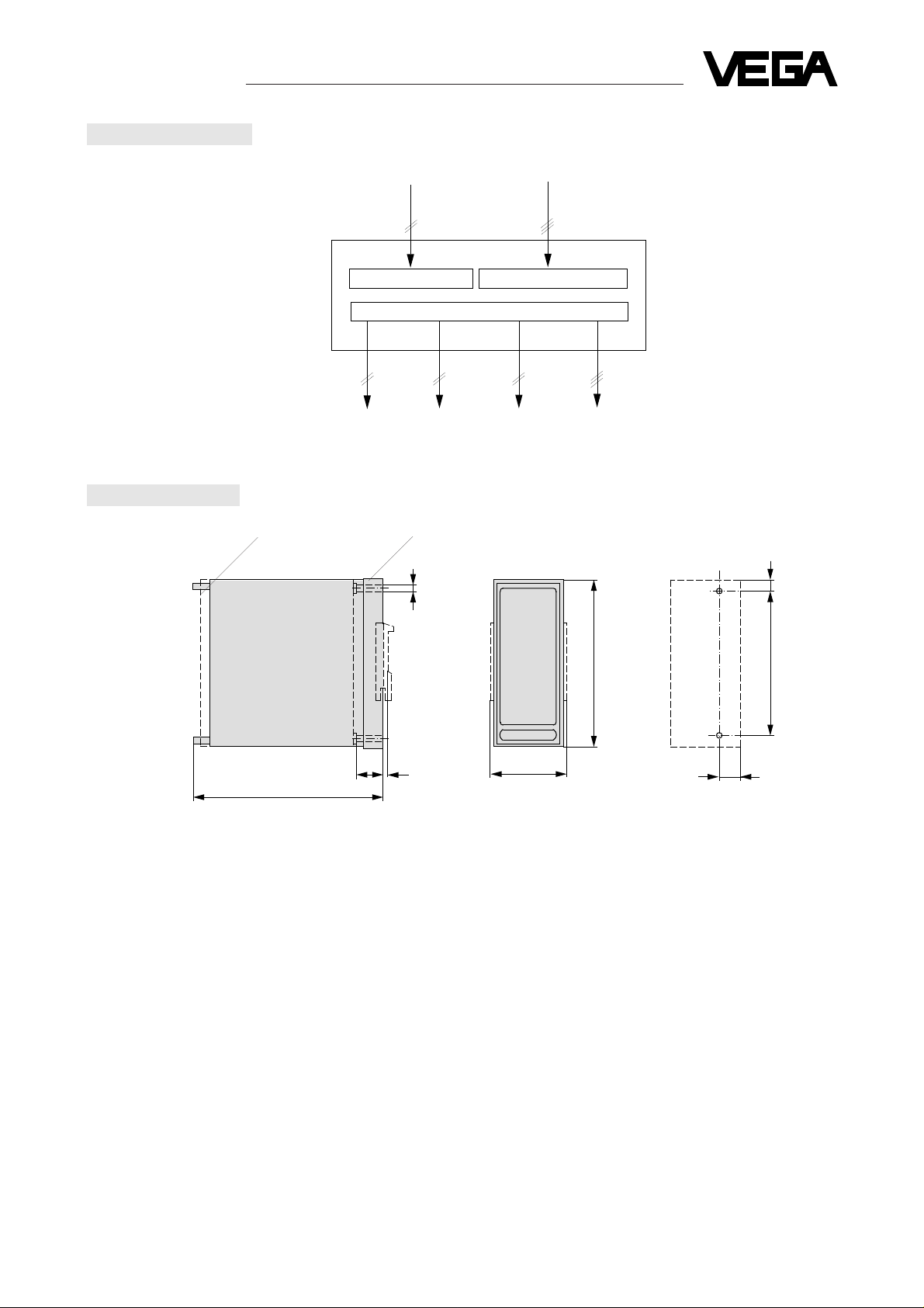
127
110
58
4,8
143
22,6
8,7
15,8
2
(dimensions in mm)
Dimensional drawing
Galvanical separation
Transparent cover Plug-in socket
Holes ø 4,5
or thread M4
Block diagram
Input Mains
Current output Voltage outputs Fail safe relay
Measuring data input Power supply
Microcomputer control and outputs
Page 6

Technical Information
Approvals
(for following measuring systems)
Approval as overfill protection acc. to
WHG
Pressure transmitters, approved for the following
measuring systems
Type .............................................................................D33, D34, D35, for type A, F, G, N, K
D36, Type G, N, F, S063
D37, Type G, N, S052
D38, Type G, N
Oscillator ................................................................... E27, E27 B
Signal conditioning instrument .................................. VEGAMET 407 Z
Auxiliary level switch .................................................. VEGASEL 444, 441 B, 441 C
defined in test certificate no. ..................................... PA-VI 810.76
Capacitive measuring electrodes, approved for the
following measuring systems
Type .............................................................................12.02, 12.12, 12.42 Ex, 12.72 Ex
22.02, 22.12
23.02, 23.12, 23.42 Ex, 23.72 Ex
25.02, 25.03, 25.12, 25.13
25.02 Ex, 25.03 Ex, 25.12 Ex, 25.13 Ex
26.02, 26.03, 26.12, 26.13
27.01, 27.11, 27.41 Ex, 27.71 Ex
32.04, 32.05, 32.14, 32.15
32.44 Ex, 32.45 Ex, 32.74 Ex, 32.75 Ex
42.04, 42.05, 42.14, 42.15
52.04, 52.05, 52.14, 52.15
Oscillator ................................................................... 117 A, 117/4 A, 117/4 A Ex
Signal conditioning instrument ................................... VEGAMET 407 Z
Auxiliary level switch ................................................. VEGASEL 444, 441 B, 441 C
defined in test certificate no. ...................................... PA-VI 870.15
If measuring systems acc. to the below approval
are installed, the legal documents have to be
observed.
Measuring systems for the use in hazardous areas
must only be operated in conjunction with pressure
transmitters or capacitive measuring electrodes in
Ex-version and safety barrier type 145.
see
- Conformity certificate
PTB-no. Ex-85.B.2038
- diagram page 7.
Page 7

Technical Information
Approvals
(continued)
Approval as overfill protection acc. to the regulation
for combustible liquids
VbF
Capacitive measuring electrodes, approved for the
following measuring systems
Type..............................................................................12.02, 12.03, 12.12, 12.13
23.02, 23.03, 23.12, 23.13
27.00, 27.01, 27.10, 27.11
32.04, 32.05, 32.06, 32.07
42.04, 42.05, 42.06, 42.07
32.14, 32.15, 32.16, 32.17
42.14, 42.15, 42.16, 42.17
12.42 Ex, 12.43 Ex, 12.72 Ex, 12.73 Ex
23.42 Ex, 23.43 Ex, 23.72 Ex, 23.73 Ex
27.40 Ex, 27.41 Ex, 27.70 Ex, 27.71 Ex
32.44 Ex, 32.45 Ex, 32.46 Ex, 32.47 Ex
32.74 Ex, 32.75 Ex, 32.76 Ex, 32.77 Ex
25.02 Ex, 25.03 Ex
25.12 Ex, 25.13 Ex
Oscillator ................................................................... 117/4 A Ex
Signal conditioning instrument .................................. VEGAMET 407 Z
Auxiliary level switch ................................................. VEGASEL 444, 441 B, 441 C
defined in test certificate no. ...................................... PTB-no. III B/S 2032 F
and type approval....................................................... 01/PTB-no. III B/S 2032 F
Transducer
(capacitive measuring electrode or
pressure transmitter)
If the sensor is installed in hazardous areas, the
special conditions of the conformity certificate must
be observed.
Signal conditoning instrument
The signal conditioning instrument VEGAMET
407 Z must be generally installed outside
hazardous areas (or special protective measures
must be taken.
Measuring systems for the use in hazardous areas
must only be operated in conjunction with pressure
transmitters or capacitive measuring electrodes in
Ex-version and safety barrier type 145. See
conformity certificate PTB-no. Ex-85.B.2038.
MOD
+
-
STO
!
t
SIM
VEGAMET
407 Z
Ex-area not Ex-area
Zone 0 Zone 1
Safety barrier
type 145
VEGAMET 407 Z
50.0 %
Page 8

Technical Information
18
17
16
15
14
13
N
L1
9
2
1
+
–
–
+
–
+
5
7
+
1
Sensor 1
1
2 3
4 … 20 mA
8
6
18
17
16
15
13
9
2
5
7
1
8
6
14
Sensor 1
1
2 3
0 … 20 mA
-
+
Electrical connection
Installation regulations:
- The wiring between VEGAMET 407 Z and sensor
(capacitive measuring electrode or pressure
transmitter) can be made with standard cable.
- In case of strong electromagnetic interferences,
screened cable must be used.
The screening must be earthed at one sensor
end.
Signal conditioning instrument
back view (type plate)
Plug-in socket with
terminals
VEGAMET 407 Z
Selection of the
current output
Alarm signals
Fault-monitoring relay
Supply voltage
(see data plate)
Voltage otuput 0 … 10 V
Voltage otuput 0 … 5 V
Current output 0/4 … 20 mA
capacitive
measuring
electrode
pressure
transmitter
Mounting instructions
14
13
VEGAMET
VEGAMET
15
14
13
15
N
L1
The plug-in base is provided with
- field terminals
- interconnection pins
- spacers for installation in series
- key coded
For installation in series the interconnection
pins are the power supply connections and
the distance sleeves ensure that adjacent
instruments have a minimum gap of 5 mm
between each other.
Remove the interconnection pins on the first
plug-in socket.
Warning: Beware of high voltage on
power supply terminals.
Plug-in base
Spacers
Key code
Interconnecting
pins for supply
voltage
In case of single mounting remove the interconnection pins and spacers, connect the supply voltage
directly.
The key coded base prevents other series 400
instruments being inserted.
Use adapter no. 040 002 for mounting on standard
rail.
Page 9

Operating surface
0407
Indication and operating elements
Measurements
Mode range
0.0
%
100.0
% Level 0 … 100 %
-10 % … 110 %
0 … 200 sec.
Adjustment in %
or in mA
Alarm signal
Empty adjustment
Full adjustment
Integration time
Simulation
Password
(Password)
MOD
+
-
STO
!
VEGAMET
407 Z
t
SIM
E1
E9
0 - -
0
Fault-monitoring LED-indication
Selection of the mode
Cursor position
Value (increase)
Value (decrease)
Storing programmed data
-8.8.8.8
PARAMETER FIELD
Measurements
MODEFIELD
%
Page 10

Operating surface
Operation
Set-up
- mounting socket
- connect capacitive measuring electrode or
pressure transmitter with the mounting socket
terminal 1 and 2, see page 8
- adjust the current output, see page 8
- check the connection and type plate
push VEGAMET 407 Z onto mounting socket and
fasten
- switch on power supply
LED (green) voltage supply lights
LED (red) fault signal lights
fault monitoring relay remains de-energized
software stage is indicated
- after approx. 2 sec.
fault-monitoring LED extinguishes
fault-monitoring relay is energized
a meaningless figure is displayed
- program empty and full adjustment, see
page 11
- if necessary, program
integration time, see page 12
password, see page 13
(procedure)
MOD
MOD
+
-
MOD
STO
SIM
0.0 %
000.0
001.6
z.B.
% %
The VEGAMET 407 Z has 3 modes which can be
obtained by scrolling the MOD-button:
Mode: 1. Measurement
2. Mode range
3. Parameter adjustment
Note that if no pushbutton is operated, after a
period of 60 minutes the display resets to level
measurement.
1. Measurement
2. Mode range
3. Parameter
adjustment
Measurement:
Level: %
Enquiry of the mode
numbers in the MODEFIELD. The parameters
of the enquired modes
can be indicated or
modified in mode 3.
Programming of the
parameters in the
PARAMETER FIELD.
The parameter of the
respectively selected
mode can be modified
and stored with the STObutton. If no change
should be realized, push
the MOD-button. In both
cases reset to mode 1.
Cursor position
Cursor position
Value (increase)
Value (decrease)
Storage
Page 11

Parameter adjustment
Empty, full adjustment in %
The measurement range for level 0 % and 100 % is
defined via the adjustment procedure.
When the vessel is partly filled or emptied the programming is as described on the right, however
with previously determined %-values.
The min. measuring range must correspond to a
current
∆ of > 300 µA.
Example
Full
• fill vessel
adjustment • select mode in MODEFIELD
• program level 100 % in
PARAMETER FIELD
• then store with STO
Empty • empty vessel
adjustment • select mode in MODEFIELD
• program level 0 % in
PARAMETER FIELD
• then store with STO
The empty and full adjustments may be performed
in any order.
%
100
0 %
Vessel full
Vessel empty
50
Empty, full adjustment in mA
The measuring current values are coordinated to
the levels 0 % and 100 % with the adjustment.
The measuring currents are experience values or
can be taken from the attached test certificate.
The procedure is used:
- for adjustment without rate of product level
change
- for correction of previous adjustments (alarm E3
or E4)
- for adjustment without connection of a capacitive
electrode or a pressure transmitter (alarm E2)
Example
Full • select mode in MODEFIELD
adjustment • push button + and button MOD
simultaneously (data input for mA)
• program 18,75 mA in
PARAMETER FIELD
• then store with STO
Empty • select mode in MODEFIELD
adjustment • push button + and button MOD
simultaneously (data input for mA)
• program 5,28 mA in
PARAMETER FIELD
• then store with STO
The empty and full adjustments may be performed
in any order.
%
100
0
mA
18,75
5,28
Level 100 %
^ measuring current
18,75 mA
Level 0 % ^
measuring current
5,28 mA
50
Page 12

Effects within the measuring range outside the measuring range
-10 % … 0 %...............100 % … 110 % < -10 % or >110 %
0/4 mA...............20 mA 22 mA
0 V..................10 V 11 V
0 V....................5 V 5,5 V
Example to end simulation ...................................... • push MOD–button again
Effects - Cancel the simulated output values
- Transmits the true output values
Parameter adjustment
Integration time
Application
- Where the product surface is agitated the system
outputs may be stabilized by adjusting the integration time.
Important notes:
The integration time depends on the filling and
emptying period of the vessel, i.e. integration time
≤ filling / emptying time. Mis-adjustment of the
integration time may degrade output sensitivity.
Definitions
- range = 0 … 199 sec.
- (0 … 199 secs. corresponds to the definition in
sec.)
At 200 sec. effects a time period, the actual value
is approx. 45 minutes.
- settings > 200 sec. are automatically limited to
the max. value 200 sec.
Example
- integration time of e.g. 15 sec.
• select mode t in MODEFIELD
• program 15 sec. in PARAMETER FIELD
• then store with STO
Example..............to activate the simulation ……… • select mode SIM in MODEFIELD
• activate the simulation with button MOD
• increase or reduce the output with button + or
button –
t
Simulation mode
In the simulation mode it is possible to test the
measuring system over the whole measuring range
independent of the process.
Button + increases and
button – reduces
all output values.
The longer the simulation button + and – are
pressed the greater the rate of change.
Integration time is ignored during the simulation
sequence.
t
fault-monitoring-LED lights
fault-monitoring relay de-energizes
Page 13

Parameter adjustment
Password
All parameters can be interrogated as previously
described and their data indicated on the display.
Data input can be inhibited by programming the
password.
Alarm signals
Indication Reason Result
Measuring results < - 10 % Input below minimum limit (flashing) without fail safe
> 110 % Input above maximum limit (flashing)
Error code E1 Connection cables reversed on with fail safe
short-circuit
E2 Line break
E3 Incomplete or incorrect adjustm. proced.
E4 (together with flashing mode segments)
E8.1 … Fault during Current output = 22 mA
E8.4 data transfer (acc. to STO) Voltage output
= 11 V or 5,5 V
E9 Fault in the EEPROM-memory
Activate password .................................................... • select mode - - - - in MODEFIELD
• program figure 1 in PARAMETER FIELD
• then store with button STO
Adjust password ....................................................... • select the mode required for parameter adjust-
ment in the MODEFIELD, in the example mode t
• select data input, the keyword 0 - - 0 is displayed
in the PARAMETER FIELD
• program
0407 as password
• then store with button STO
• the parameter adjustment of e.g. mode
t can be
made
(fail safe)
Page 14

Alarm information
E1 E2
1
2
+
-
VEGAMET 407 Z
V
mA
4 … 20
12 … 24
2
1
2
1
Sensors Measuring line
Capacitive Pressure
measuring transmitter
electrode
Fault diagnosis related to E1 or E2
Signal conditioning
instrument
Short-circuit
current > 22 mA
Check all connections
and measuring lines
Yes
No
Yes
No
Yes
No
Yes
No
Yes
No
Yes
No
Shortcircuit
removed
?
Short-
circuit
removed
?
Short-
circuit
removed
?
Sensor defect
Short-circuit in the
connection cable
Separate sensor from
connection cable
Separate signal conditionining
instrument from connection cable
Line break
current < 2 mA
Check supply voltage
and measuring line
Signal conditioning
instrument defect
approx.
24 V
?
Alarm
E1 dis-
played?
Alarm
E1 is
displayed
?
Auswertgerät defekt
Fault or break on the
sensor (capacitive
measuring electrode or
pressure transmitter)
Cable break
Short-circuit the signal conditioning
instrument terminals
Remove short-circuit of the terminals on the
signal conditioning instrument, then short-
circuit terminal 1 and 2 on the sensor
Signal conditioning
instrument defect
E1 extinguishes
Signal conditioning
instrument defect
Page 15

Help for fault diagnosis The measuring current stored during empty and full
adjustment can be displayed in the mode range by
pushing the plus-button.
Application with …………………… - inaccurate measurements or
- alarm E3 or E4
Example: Measuring current of the previous
adjustment related to 0 % • select mode in MODEFIELD
• push plus-button, the adjustment current related
to 0 %, is displayed in PARAMETER FIELD
• reset by pushing the MOD-button twice
Measuring current of the previous
adjustment related to 100 % • select mode in MODEFIELD
• push plus-button, the adjustment current related
to 100 %, is displayed in PARAMETER FIELD
• reset by pushing the MOD-button twice
Alarm information
E3
E4
= Adjustment had been carried with no or with too
small level change.
= The modes or %-values had been exchanged
during adjustment
or
Fault diagnosis related to E3
Fault diagnosis related to E4
Alarm
removed
?
Repeat the adjustment
(e.g. empty adjustment)
Repeat the 2nd part of the
adjustment (e.g. full
adjustment)
or carry out
adjustment in mA
see page 11
E3 or E4 and mode
segment extinguish
E3 or E4 and
mode segment extinguish
Note
- %-value and
- mode
Note:
min. measuring
distance; %value and mode
Page 16

VEGA Grieshaber KG
Am Hohenstein 113
Postfach 11 42
D-77757 Schiltach
Phone 0 78 36/50-0
Technical data subject to alterations
2.12 245 / März '94
Alarm information
E8.1
Fault diagnosis related to E 8.1
The empty adjustment data has not been transferred
Repeat empty adjustment,
see page 11
Alarm E 8.1 extinguishes
O.K.
?
Auswertgerät defekt
E8.2
The full adjustment data has not been transferred
Repeat full adjustment,
see page 11
Alarm E 8.2 extinguishes
O.K.
?
Auswertgerät defekt
E8.3
The integration time data has not been transferred
Repeat programming of integration
time, see page 12
Alarm E 8.3 extinguishes
O.K.
?
Auswertgerät defekt
E8.4
The password data has not been transferred
Repeat activation or adjustment of
password, see page 13
Alarm E 8.4 extinguishes
O.K.
?
Auswertgerät defekt
E9
Try a new set-up, see page 10
Alarm E 9 extinguishes
O.K.
?
Auswertgerät defekt
Fault (data loss) in the EEPROM-memory
Yes
No
Yes
No
Yes
No
Yes
No
Yes
No
Signal conditioning
instrument defect
Signal conditioning
instrument defect
Signal conditioning
instrument defect
Signal conditioning
instrument defect
Signal conditioning
instrument defect
 Loading...