

Page 1
VEGAMET 407 AF
VEGAMET 407 AFT
TIB • Technical Information • Operating Instructions
Signal conditioning
instrument
For continuous level
measurement
- for connection of a
capacitive electrode
- or a pressure sensor
VEGA Grieshaber KG
Am Hohenstein 113
Postfach 11 42
D-77757 Schiltach
Phone 0 78 36/50-0
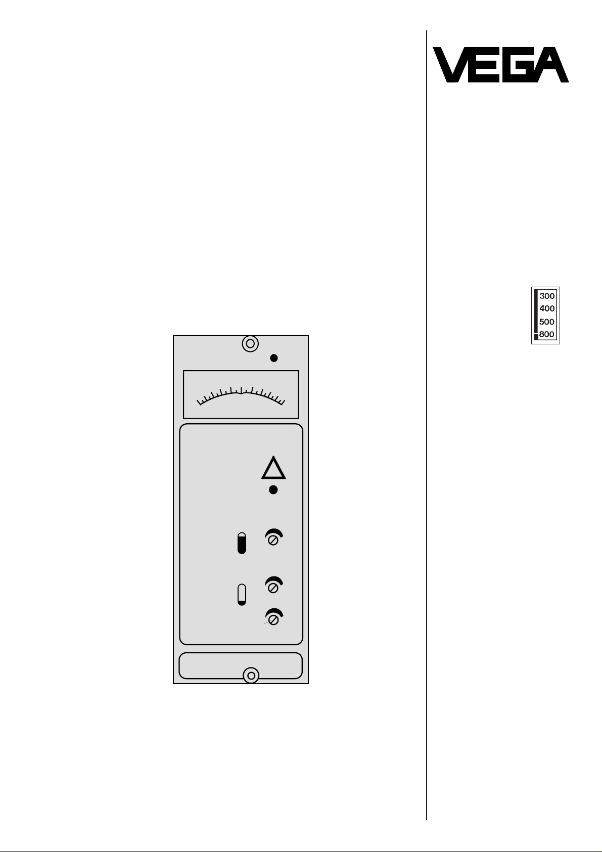
407 AF
100
0
50
%
tj
0
VEGAMET
!
Page 2

Application
The VEGAMET 407 AF or 407 AFT is a signal conditioning instrument and is used for level propor-
tional indication (continuous level measurement).
The VEGAMET 407 AF or 407 AFT consists of:
- plastic housing with plug-in socket (series400)
- electronics
- relay output with floating spdt (fail safe)
- front plate with:
- mains control lamp
- indicating instrument
- signal lamp
- potentiometer for full adjustment
- potentiometer for empty adjustment
- potentiometer for integration time
A measuring system consists of:
- signal conditioning instrument VEGAMET 407 AF
or 407 AFT
- capacitive electrode with oscillator or pressure
sensor with oscillator
Additional indicating instruments and auxiliary level
switches can be connected to the current and
voltage output.
Level measurement with capacitive electrodes
a) non-conductive products
Electrode and container wall form a capacitor.
The level changes the dielectric of the capacitor
and therefore its capacitance.
b) conductive products
The fully insulated electrode and product form a
capacitor. The level changes the size of the
capacitor and therefore its capacitance.
In both cases a level proportional measuring current is generated in the oscillator from the capacitance change.
Fault monitoring
The integral fault monitoring detects
- short-circuit or line break of the connection line
to the transducer
- current value of the connection line < 2,5 mA or
> 23,5 mA (e.g. as well as failures of the electronics in the transducer)
If one of the above mentioned failures is detected,
the failure LED lights and the output relay de-energizes, i.e. terminal 16 and 17 are connected
through relays (see electrical connection).
In addition more the output current increases to
approx. 23 mA and the voltage outputs take a
value< 5 V or < 10 V.
Current output
VEGAMET 407 AF
The current output of VEGAMET 407 AF is nonfloating with reference to the sensor input and
voltage output, however is floating with reference to
the mains connection.
VEGAMET 407 AFT
The current output of VEGAMET 407 AFT is floating.
Level measurement with pressure sensors
The diaphragm of the pressure sensor converts the
hydrostatic pressure of the product linear into a
movement. This movement changes the size of a
capacitor.
The respective oscillator generates a level proportional current out of this capacitance change.
The VEGAMET 407 AF or 407 AFT evaluates the
measuring current several times (see page 5).
Integration time
In case of fluctuating product surface it is useful to
smooth the outputs (indication, output 1 - 3), by
adjusting an integration time 0 … 20 sec.
Important note
The period of the integration time orientates on the
filling and emptying time of the vessel, i.e. integration time ≤ filling / emptying time.
Configuration
Function
Page 3

Technical data
Power supply Value Tolerance Frequency
standard AC 220 V +15 % -10 % 50 / 60 Hz
AC 230 V +10 % -15 %
options AC 110 V 50 / 60 Hz
130 V +15 %
240 V -10 %
260 V
AC 24 V +15 % 50 / 60 Hz
42 V -10 %
48 V
DC 9 … 16 V
16 … 60 V
Power consumption at UN: approx. 7 VA
Voltage for the transducer on
terminals 1 and 2 (terminal 3 and 4 bridged) approx. 22 V
Resistance per conductor to the transducer max. 50 Ohm
Voltage for the transducer on
terminals 1 and 2 (terminal 3 and 4 open)
(only for electrodes with oscillator type 117) approx. 15 V
Resistance per conductor to the transducer max. 50 Ohm
Indication analog indication 0 … 100 %
Output 1 type current output
range 0 … 20 mA or 4 … 20 mA
load max. 750 Ohm
floating VEGAMET 407 AFT
Output 2 type current output
range 0 … 5 V, max. 2 mA
for connection of
max. 10 auxiliary limit switches VEGASEL
Output 3 type voltage output
range 0 … 10 V, max. 2 mA
Output 4 type relay output
function fail safe
contact 1 spdt
relay data:
contact material AgCdO and Au plated
min. turn-on voltage 10 mV
switching current 10
µA
max. turn-on voltage AC 250 V, DC 60 V
switching current AC 2 A, DC 1 A
breaking capacity 125 VA, 60 W
Integration time 0 … 20 sec.
Permissible ambient temperature on the housing -20°C … +50°C / -4 … 122°F
Storage and transport temperature -20°C … +70°C / -4 … 158°F
Housing type plastic ABS light grey
protection IP 40
dimensions B = 53 mm, T = 143 mm, H = 127 mm
Terminal board: for cross section area of conductors max. 1 x 1,5 mm
2
Weight: with plug-in socket approx. 710 g
Page 4

Mounting instructions
Dimensional drawing
14
13
N
L1
VEGAMET
VEGAMET
15
14
13
15
The mounting assembly is provided as
standard feature with
- respective terminals
- interconnection pins
- distance sleeves for mounting
several instruments in a row
- coded key
Spacers slide onto the interconnecting
pins and ensure that adjacent instruments have a minimum gap of 5 mm
between each other.
For mounting on standard rail
(TS 35 mm) an adapter is enclosed.
The two screws located on the front of
the instrument are used to fasten the
instrument to the mounting assembly.
In case of single mounting remove the
interconnection pins and connect the
supply voltage directly. The coded key
avoids that instruments of series 400
are exchanged.
Remove all interconnection pins on the
first plug-in socket.
Attention:
The pins on terminals 13, 14 and 15 carry the supply
voltage.
127
110
58
4
143
22,6
8,7
15,8
2
Dimensions in mm Holes ø 4,5
or thread M4
transparent cover Plug-in socket
Plug-in socket
Distance sleeves
Coded key
Interconnecting pins
for supply voltage
Page 5

Electrical connection
The electrical connections should be made on the
mounting assembly in accordance with the diagram
located on the back of the instrument.
Standard two-wire cable can be used as measuring
line, electrode and signal conditioning instrument.
If electromagnetic interferences have to be
expected, screened cable must be used.
As factory preset, the terminals 3 and 4 are bridged
(supply voltage for oscillator: 22 V DC)
Attention:
In conjunction with oscillator type 117 the bridge
must be removed!
(Therefore supply voltage for oscillator: 12 V DC)
Protective measures:
If there is a danger of voltage spikes overvoltage
arresters are recommended.
Note TIB "Overvoltage arresters" for connection.
18
17
16
15
14
13
N
L1
9
2
1
+
-
-
+
-
+
5
7
+
1
4 … 20 mA
8
6
0 … 20 mA
2
1
2
1
3
4
Output 1 2 3
Indicated Current Voltage Voltage
value output output output
0 % 0 / 4 mA 0 V 0 V
100 % + 20 mA - 5 V - 5 V
Relay output
(fail safe)
Mains connection
Voltage output 0 … 10 V
Voltage output 0 … 5 V
Current output 0/4 … 20 mA
Wiring bridge
Measuring line
Electrode with
oscillator
Pressure sensor
with oscillator
Page 6

- Feed supply voltage.
The voltage must comply
with the figure stated on the wiring diagram.
- Adjust changeover switch on the back of the
instrument or on the front plate to the desired
current output range 0 … 20 mA or 4 … 20 mA
- turn potentiometer for integration time complete-
ly anti-clockwise
- potentiometer for full adjustment must be turned
clockwise by 22 turns
- Carry out adjustment as follows
Adjustment
The full or empty adjustment is carried out by a
spindle potentiometer. Overwinding is avoided by
the slide clutch. In practice three different methods
are possible for empty / full adjustment:
a) Level in the vessel can be filled to the
required min. level (= 0 %) and max. level
(= 100 %)
Empty adjustment
- Reduce product to required min. level.
- Adjust with potentiometer for empty adjustment
the indication of the instrument to 0 %.
Full adjustment
- Increase product to required max. level.
- Adjust with potentiometer for full adjustment the
indication of the instrument to 100 %.
Integration time
- Adjust potentiometer for integration time to
required value (see page 2).
b) Level in the vessel can be filled to the
required min. level (= 0 %), but only to a max.
level < 100 %
Empty adjustment
- Reduce product to required min. level.
- Adjust with potentiometer for empty adjustment
the indication of the instrument to 0 %.
Full adjustment
- Increase product to max. possible level and
dipcheck (e.g. 80 %)
- Adjust with the potentiometer for full adjustment
the indication of the instrument to the checked
value.
Integration time
- Adjust potentiometer for integration time to
required value (see page 2).
c) Level in the vessel can only be reduced to a
min. level > 0 % and to a max. level ≤ 100 %
Empty adjustment
- Reduce product to min. possible level and
dipcheck (e.g. 20 %)
- Adjust with the potentiometer for empty adjustment the indication of the instrument to the
checked value.
Full adjustment
- Increase level to max. possible level and
dipcheck (e.g. 60 %)
- Calculate indication value to be adjusted:
max. level minus min. level = indicating value to
be adjusted.
in the example: 60 % - 20 % = 40 %
- Set with the potentiometer for full adjustment the
indication of the instrument to the calculated
value (in the example 40 %).
- Set with the potentiometer for empty adjustment
the indication of the instrument to the actual
level (max. level in the example 60 %).
Integration time
- Adjust with potentiometer for integration time to
required value.
407 AF
100
0
50
%
tj
0
VEGAMET
Start-up
Fixing screw
Fixing screw
Mains control lamp
Indication instrument
Signal lamp
Potentiometer
for full adjustment
Potentiometer
for empty adjustment
Potentiometer
for integration time
Page 7

Example
100 %
0 %
90 %
10 %
-
+
L1
N
18
17
16
15
14
13
PE
0 … 20 mA
(+) N
(-) L1
4 … 20 mA
9
8
7
6
5
4
3
2
1
+
+
+
-
+
2
1
2
1
K2
18
17
16
15
14
13
PE
N
L1
12
11
10
8
7
L1
K2
N
Automatic emptying of a vessel
At a level of 90 % the pump is switched on and at
10 % level switched off.
Filling
Electrode
Pump Pressure sensor
Signal condition-
ing instrument
VEGAMET
Indicating
instrument
Auxiliary limit switch
VEGASEL
Signal lamp
Mains connection
Wiring bridge
VEGAMET 407 AF (T) VEGASEL 444
empty
channel
1 "A"
Input
signal
0 … 5 V
channel
1 "B"
Electrode
Pressure sensor
Indicating
instrument
0/4 … 20 mA
Page 8

VEGA Grieshaber KG
Am Hohenstein 113
Postfach 11 42
D-77757 Schiltach
Phone 0 78 36/50-0
Mounting instructions
Channel 1: A/B-switch in position A
one-point position 90 %
Channel 2: A/B-switch in position B
one-point position10 %
K2
K2
N
K2
11
10
11
12
16
17
L1
B
A
Control
pump
empty
 Loading...