

Page 1
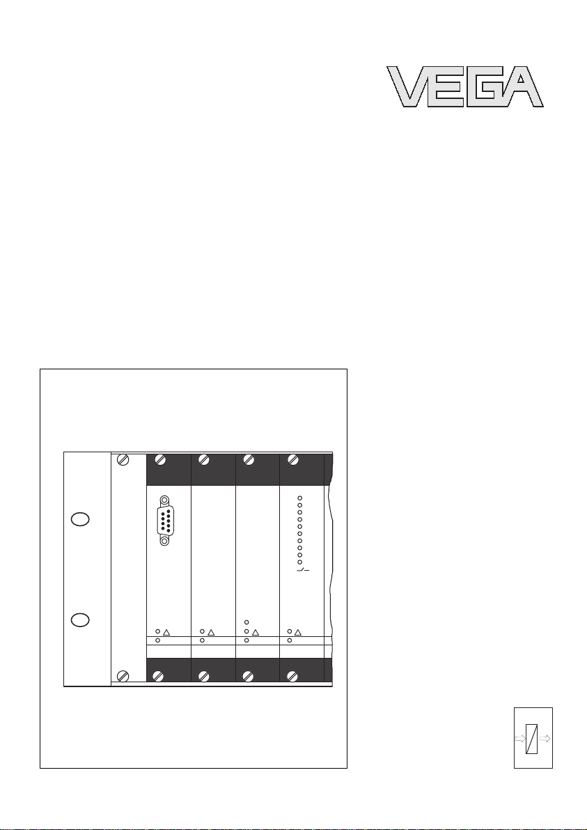
Operating Instructions
VEGALOG 571
CPU and carrier
on on
on
PC
on
VEGALOGVEGALOG
1
2
3
4
5
6
7
8
9
10
571 CPU
VEGALOGVEGALOG
571 EA
VEGALOGVEGALOG
571 EP
VEGALOGVEGALOG
571 AR
!
!
!
!
BA
inin
outout
Page 2

Contents
1 About this document
1.1 Function .............................
4
1.2 Target group ..........................
4
1.3 Symbolism used .......................
4
2 For your safety
2.1 Authorised personnel....................
5
2.2 Appropriate use........................
5
2.3 Warning about misuse ...................
5
2.4 CE conformity .........................
5
2.5 Environmental instructions ................
6
3 Product description
3.1 Configuration..........................
7
3.2 Principle of operation ....................
7
3.3 Operation ............................
8
3.4 Storage and transport ...................
8
4 Mounting
4.1 General instructions.....................
10
4.2 Carrier ..............................
10
4.3 Mount female multipoint connectors .........
11
4.4 Coding ..............................
11
5 Connecting to power supply
5.1 General connection instructions ............
14
5.2 Additional instructions for Ex applications .....
15
5.3 Wiring plan ...........................
16
6 Set up
6.1 Indicating and adjustment elements .........
19
6.2 Module card types......................
19
6.3 Setup requirements .....................
22
6.4 Start PACTware™ .....................
23
6.5 Creating a project ......................
24
6.6 Example projects.......................
25
6.7 Parameter adjustment ...................
26
7 Maintenance and fault rectification
7.1 Maintenance ..........................
30
7.2 Fault rectification .......................
30
7.3 Instrument repair .......................
31
2 VEGALOG 571 - CPU and carrier
Contents
31947-EN-060606
Page 3

8 Dismounting
8.1 Dismounting procedure ..................
32
8.2 Disposal .............................
32
9 Supplement
9.1 Technical data.........................
33
9.2 Dimensions ...........................
35
VEGALOG 571 - CPU and carrier 3
Contents
31947-EN-060606
Page 4
1 About this document
1.1 Function
This operating instructions manual has all the information you
need for quick setup and safe operation. Please read this
manual before you start setup.
1.2 Target group
This operating instructions manual is directed to trained,
qualified personnel. The contents of this manual should be
made available to these personnel and put into practice by
them.
1.3 Symbolism used
Information, tip, note
This symbol indicates helpful additional information.
Caution: If this warning is ignored, faults or
malfunctions can result.
Warning: If this warning is ignored, injury to persons and/or
serious damage to the instrument can result.
Danger: If this warning is ignored, serious injury to persons
and/or destruction of the instrument can result.
Ex applications
This symbol indicates special instructions for Ex applications.
l List
The dot set in front indicates a list with no implied sequence.
à Action
This arrow indicates a single action.
1 Sequence
Numbers set in front indicate successive steps in a procedure.
4 VEGALOG 571 - CPU and carrier
About this document
31947-EN-060606
Page 5

2 For your safety
2.1 Authorised personnel
All operations described in this operating instructions manual
must be carried out only by trained specialist personnel
authorised by the operator. For safety and warranty reasons,
any internal work on the instruments must be carried out only
by personnel authorised by the manufacturer.
2.2 Appropriate use
VEGALOG 571 is a modular processing system for a wide
range of applications, e.g. for level, process pressure and
differential pressure measurement.
2.3 Warning about misuse
Inappropriate or incorrect use of the instrument can give rise to
application-specific hazards, e.g. vessel overfill or damage to
system components through incorrect mounting or adjustment.
2.4 General safety instructions
VEGALOG 571 CPU is a high-tech instrument requiring the
strict observance of standard regulations and guidelines. The
user must take note of the safety instructions in this operating
instructions manual, the country-specific installation standards
(e.g. the VDE regulations in Germany) as well as all prevailing
safety regulations and accident prevention rules.
2.5 CE conformity
The VEGALOG 571 CPU(Ex) module card is in CE conformity
with EMVG (89/336/EWG) and LVD (73/23/EWG).
Conformity has been judged according to the following
standards:
l EMC:
- Emission EN 50081-2
- Susceptibility EN 50082-1
l LVD: EN 61010
VEGALOG 571 - CPU and carrier 5
For your safety
31947-EN-060606
Page 6

2.6 Environmental instructions
Protection of the environment is one of our most important
duties. That is why we have introduced an environment
management system with the goal of continuously improving
company environmental protection. The environment management system is certified according to DIN EN ISO 14001.
Please help us fulfil this obligation by observing the environmental instructions in this manual:
l Chapter "Storage and transport"
l Chapter "Disposal"
6 VEGALOG 571 - CPU and carrier
For your safety
31947-EN-060606
Page 7

3 Product description
3.1 Configuration
The scope of delivery encompasses:
l 19" module card VEGALOG 571 CPU
l 19" carrier with integrated bus board
l Female multipoint connectors with card guide, screws and
coded pins (optional)
l Documentation
- this operating instructions manual
- Ex-specific "Safety instructions" (with Ex versions)
- if necessary, further certificates
A VEGALOG 571 processing system consists of a CPU, one
or several peripheral cards as well as a power supply unit
which are inserted into the 19" carrier BGT LOG 571. CPU and
peripheral card are designed as module cards in European
size (DIN 41494) with 5 TE width (25.4 mm). The supply
voltage of the cards with 24 VDCis provided e.g. via a power
supply unit VEGASTAB 593. The carrier with a width of 84 TE
and a height of 3 HE corresponds to the 19" standard format,
however, has an integrated LOGBUS board for communication
among the cards.
The maximum configuration of a VEGALOG consists of two
carriers mounted above one another with one CPU, 31
peripheral cards and one power supply unit. With this
configuration, up to 255 measurement loops can be set up.
3.2 Principle of operation
VEGALOG 571 is a modular processing system for a wide
range of applications, e.g. for level, process pressure and
differential pressure measurement.
To suit the application and the individual requirements,
VEGALOG 571 is put together using several module cards. A
CPU card and different input/output cards are available which
are inserted into a 19" carrier.
To suit these applications, VEGALOG 571 powers the
connected sensors and processes their analogue/digital
measuring signals or switching commands. The peripheral
cards take over the power supply as well as the processing of
the measuring signals. The processing is carried out in the
CPU through a special software consisting of function
Scope of delivery
Area of application
Physical principle
VEGALOG 571 - CPU and carrier 7
Product description
31947-EN-060606
Page 8

components (FB), input components (EB) and output components (AB). The input components receive the measuring
signals, the output components make them available via the
hardware outputs of the peripheral cards or the CPU. The
communication among the individual cards is carried out via an
own bus system (LOGBUS).
On the input side, 0/4 … 20 mA current outputs or Profibus PA
inputs are available. On the output side, there are relay or
current outputs. In addition, digital output cards for Ethernet,
Profibus, Modbus, Interbus and RS232/ASCII are available.
Voltage is supplied by a 19" power supply unit type
VEGASTAB. Detailled information on the voltage supply is
available in the "Technical data" in the "Supplement".
3.3 Operation
The operation of VEGALOG 571 is carried out via a PC which
can be connected via the RS232 interface of the CPU. Asan
alternative, connection via Ethernet and VEGACOM 558 is
possible.
The adjustment software PACTware™ with the corresponding
DTMs is installed under Windows™ and ensures easy
configuration of measuring systems as well as parameter
adjustment of connected VEGA sensors. For this purpose,
PACTware™ provides a clear adjustment interface with menu
structure, window technology and graphic support. In addition,
online help is available which describes the available functions
and parameter adjustment options. For earlier VEGALOG
systems with CPU software 1.xx, the previous software VVO
(VEGA Visual Operating) must be used for operation.
3.4 Storage and transport
Your instrument was protected by packaging during transport.
Its capacity to handle normal loads during transport is assured
by a test according to DIN EN 24180.
The packaging of standard instruments consists of environ-
ment-friendly, recyclable cardboard. For special versions, PE
foam or PE foil is also used. Dispose of the packaging material
via specialised recycling companies.
l Storage and transport temperature see "Supplement -
Technical data - Ambient conditions"
Power supply
Packaging
Storage and transport tem-
perature
8 VEGALOG 571 - CPU and carrier
Product description
31947-EN-060606
Page 9

l Relative humidity 20 … 85 %
VEGALOG 571 - CPU and carrier 9
Product description
31947-EN-060606
Page 10
4 Mounting
4.1 General instructions
The module cards of VEGALOG 571 can only be mounted into
the 19" carrier BGT LOG 571. It is provided with a special bus
board for data transmission between CPU and the individual
peripheral cards (LOGBUS). The carrier is designed for
mounting into a switching cabinet or 19" housing.
The plug position for the individual cards is individually
selectable, the system saves the card positions when switching on.
Note:
The plug positions must not be changed after the parameter
adjustment because measurement loops that have already
been set up would otherwise have to be reconfigured.
4.2 Carrier
By means of the plug connectors on the bus board, a fixed
pattern is created for the use of the modules. This ensures that
each module card is plugged into the multipoint connector and
also into its LOGBUS socket.
l Number of subunits (TE)
- 84 TE, thereof one 4 TE blind cover on module 1
l Width of the module cards
- 5 TE for CPU and peripheral cards
- 10 TE for VEGASTAB 593
l Number of module cards in the BGT LOG 571
- max. 16 pcs.(e.g. 1x VEGASTAB 693, 1x CPU and
13x peripheral cards)
A VEGALOG 571 in the maximum configuration consists of
two completely equipped carriers which are connected to each
other via a pluggable bus cable (see "Chapter Electrical
connection"). Because the bus cable may not be lengthened,
the two carriers must be mounted directly above one another.
Note:
In the following cases, it is recommended to mount a 19"
ventilator to avoid a temperature increase in VEGALOG.
l If more than one carrier is placed above the other
l If air cannot circulate in the area of the carrier
10 VEGALOG 571 - CPU and carrier
Mounting
31947-EN-060606
Page 11
l With increased ambient temperatures
4.3 Mount female multipoint connectors
The carrier BGT LOG 571 is supplied completely assembled.
To mount the individual module cards, modules must be
provided in the requested positions. A module consists of:
l a female multipoint connector according to DIN 41612,
series F, 48-pole
l two fixing screws
l two coded pins
l two guide rails
The female multipoint connector is available with the following
connections:
l Wire-Wrap standard connection 1.0x1.0 mm
l Plug connection 2 .8x0.8 mm
l Termi-Point standard connection 1.6x0.8 mm
l Soldering connection
l Screw terminals 0.5 mm²
If the VEGALOG 571 is supplied completely with carrier and
peripheral cards, the modules are completely mounted and
voltage supply for the individual cards is already looped. In
case of part or supplementary orders, the female multipoint
connectors must be mounted in the requested position by
means of the attached screws. Also the card guides must be
plugged in the corresponding positions. To complete the
setup, connect the 24 V supply voltage, the terminal assignment is stated in chapter "Connecting to power supply".
Tip:
Determine the position of the individual cards now and plug in
the coded pins as described in chapter "Coding".
4.4 Coding
A mechanical coding system avoids later interchanging of the
various module cards in the carrier.
The coding system consists of:
l two coded pins in the female multipoint connector
l two holes in the male multipoint connector of the respective
component
The coded pins are attached to the module.
VEGALOG 571 - CPU and carrier 11
Mounting
31947-EN-060606
Page 12

Equip the female multipoint connector with the two coded pins
according to the "Coding chart" and "Position of the coded
pins". The function coding points out that these are module
cards of VEGALOG. The instrument coding is used to
differentiate between the individual module cards.
The male multipoint connectors of the individual module cards
point to the holes suiting the pin positions.
Instrument coding Function coding
CPU card a1 c3
EP card a3 c3 and c23 with Ex
AA card a5 c3
AR card a7 c3
AT card a9 c3
EA card a11 c3
VEGACOM 557 a27 c3, c11
VEGACOM 558 a29 c11
VEGASTAB 593 -- --
o 9 o
z b d
o 1 o
a c
a1
a3
a5
a7
o 3 o
o 5 o
o 7 o
o11o
o13o
o15o
c3
o17o
o19o
o21o
o23o
o25o
o27o
o29o
o31o
a9
a11
a13
c11
c23
a23
a25
a27
3
1
2
Fig. 1: Positioning of the coded pins on the male multipoint connector
1 Instrument coding
2 Function coding
3 Ex coding
12 VEGALOG 571 - CPU and carrier
Mounting
31947-EN-060606
Page 13

1
Fig. 2: Detail coded pin mounting
1 Coded pin
VEGALOG 571 - CPU and carrier 13
Mounting
31947-EN-060606
Page 14

5 Connecting to power supply
5.1 General connection instructions
Always observe the following safety instructions:
l Connect only in the complete absence of line voltage
l If overvoltage surges are expected, overvoltage arresters
should be installed
In hazardous areas you should take note of the appropriate
regulations, conformity and type approval certificates of the
sensors and power supply units.
The VEGALOG cards must be powered with extra low voltage
(24 VDC) to keep protection class II. Detailled infromation to
voltage supply is available in the "Technical data" in the
"Supplement". When using a VEGASTAB 593, a reliable
separation from the mains circuits is ensured according to DIN
VDE 0106, part 101.
If voltage supply is not taken over by VEGASTAB, the supply
cable must be looped via the supplied NF filter (type: Schaffner
FN660-10/06). The supply cable after the filter must be wired
with a considerable distance to the signal cables to avoid
couplings.
Note:
Sum the power consumptions of the individual cards and
sensor and select a power supply unit with sufficient power
reserve.
Power supply is connected with standard cable acc. to the
national installation standards.
To connect 4 … 20 mA instruments, standard two-wire cable
without screen can be used. If electromagnetic interference is
expected which is above the test values of EN 61326 for
industrial areas, screened cable should be used.
When connecting Profibus PA sensors, screened cable
according to Profibus specification must be used.
Please make sure that your installation is carried out according
to the Profibus specification. In particular, make sure that the
termination of the bus is done with appropriate terminating
resistors.
Note safety instructions
Take note of safety
instructions for Ex
applications
Select power supply
Selecting the connection ca-
ble
14 VEGALOG 571 - CPU and carrier
Connecting to power supply
31947-EN-060606
Page 15

Connect the cable screen on both ends to ground potential. In
the sensor, the screen must be connected directly to the
internal ground terminal. The ground terminal outside on the
sensor housing must be connected to the potential equalisation (low impedance).
If potential equalisation currents are expected, the screen
connection on the side of VEGALOG 571 CPU must be made
via a ceramic capacitor (e.g. 1 nF, 1500 V). The low frequency
potential equalisation currents are thus suppressed, but the
protective effect against high frequency interference signals
remains.
Take note of the corresponding installation regulations for Ex
applications. In particular, make sure that no potential equalisation currents flow over the cable screen. In case of
grounding on both sides this can be achieved by the use of a
capacitor or a separate potential equalisation.
The total capacitance of the cable and of all capacitors must
not exceed 10 nF in Ex applications.
5.2 Additional instructions for Ex applications
Applications in the area according to the CENELEC Ex
protective reguations and ElexV (Germany) zone 0 require the
use of approved sensors.
For these applications, not the respective legal documents
(test certificates, test notes and conformity certificates). These
belong to the scope of delivery of the respecitive instrument.
These sensors must only be powered via an intrinsically safe
circuit. With the EA card, the sensors must be connected via a
safety barrier. The EP card is available in Ex version, no
separate separating facility necessary.
Also note the legal documents of these instruments.
To mount, note the following:
l VEGALOG 571 as well as the used separting facilities
must be only used outside the Ex area.
l A separating wall must be provided between the con-
nection parts of intrinsically safe and non-intrinsically safe
circuits so that there is a min. distance of 50 mm
l Only one sensor must be connected to each safety barrier
Cable screening and grounding
Select connection
cable for Ex applications
Mounting instructions
VEGALOG 571 - CPU and carrier 15
Connecting to power supply
31947-EN-060606
Page 16

5.3 Wiring plan
3
1
2
Fig. 3: Connection with NF filter
1 Supply cables
2 NF filter
3 Signal cables
2
1
L (+)
N (-)
2
6
12
20
24
22
10
16
18
30
28
32
dbz
14
26
8
4
Fig. 4: Terminal assignment VEGALOG 571 CPU
1 Supply voltage
2 The contacts (d/b/z 4 to d/b/z 32) are free
BGT/NF filter
CPU card
16 VEGALOG 571 - CPU and carrier
Connecting to power supply
31947-EN-060606
Page 17

Coupling of the carriers
If the number of the available modules of a carrier (BGT) is not
sufficient, the VEGALOG 571 can be also completed with a
second BGT.
The carriers are place above another and connected via the
supplied ribbon cable. On the rear of the bus board there is an
appropriate plug connection.
For the configuration with two carriers you have to set the
following two switch positions according to below description.
l Hook switch for the termination resistor
l Slide switch
Hook switch - closed
Slide switch - position M
l BGT 1
- Hook switch - closed
- Slide switch - position M
l BGT 2
- Hook switch - open
- Slide switch - position S
Switch position, one BGT
Switch position, two BGT
VEGALOG 571 - CPU and carrier 17
Connecting to power supply
31947-EN-060606
Page 18

M
S
M
S
5
4
3
2
1
Fig. 5: Coupling of two carriers
1 Hook switch
2 Slide switch
3 BGT 1 (modules 1 … 16)
4 Bus cable
5 BGT 2 (modules 17 … 32)
18 VEGALOG 571 - CPU and carrier
Connecting to power supply
31947-EN-060606
Page 19

6 Set up
6.1 Indicating and adjustment elements
1
2
3
on
PC
VEGALOGVEGALOG
571 CPU
!
Fig. 6: Indicating and adjustment elements VEGALOG 571 CPU
1 RS232 interface
2 LED for fault signal
3 LED for operating voltage
l LED fault signal [1]
- flashes in case of communication problems on the
LOGBUS
- lights during initialisation and during the self-test
- lights permanently during a hardware error
l LED operating voltage [2]
- lights when voltage supply is on
The module cards of the VEGALOG system have no own
adjustment elements. All adjustment measures are carried out
through the PC via the adjustment software PACTware™.
6.2 Module card types
The modular system of VEGALOG 571 consists of different,
special module card types:
l CPU card
Description of the status
LEDs
VEGALOG 571 - CPU and carrier 19
Set up
31947-EN-060606
Page 20

l Input cards
l Output cards
l Communication cards for standard bus systems
l Power supply cards for supply of the individual module
cards
The processor card is the centre of VEGALOG. It has the
following functions:
l Communication handling among the individual cards
l Creating and administrating of individual measurement
loops
l Calculating tasks such as adjustment, scaling, linearisa-
tion, differential generation etc.
l Coupling to the PC via RS232 interface
The CPU is further used for detection of levels or for monitoring
the switching on and switching off times.
The CPU read cyclically measured values from the peripheral
cards (e.g. with 30 measurement loop in the 300 ms cycle).
These are compared with the programmed data, standardised
and processed. The programmed data (configuration data,
adjustment parameters etc.) are available in the EEPROM
where they remain even in case of voltage loss. In the memory
of the CPU, a process picture is created which is outputted to
the peripheral cards via LOGBUS.
For backup, the programmed data can be read out any time via
the RS232 interface and can then be saved on the PC.
EA card
Up to ten 0/4 … 20 mA instruments can be connected to the
EA card (Eingang Analog, i.e. input analogue), e.g.:
l Capacitive probes
l Hydrostatic pressure transmitters
l Vibrating level switches
l Conductive probes
l Process and differential pressure transmitters
l Switching contacts (level signaller)
The inputs can be connected actively (sensor is powered by
the EA card) or passively (sensor delivers current).
Within an EA card, mixed connection of active/passive inputs
is permitted.
CPU card
Input cards
20 VEGALOG 571 - CPU and carrier
Set up
31947-EN-060606
Page 21

EP card
The EP card (Eingang Profibus PA, i.e. input PROFIBUS PA)
is used as input card for Profibus PA sensors of VEGA or other
manufacturers. Up to max. 15 Profibus PA sensors (max. 10
with Ex version) can be connected.
The EP (Ex) card recognises VEGA sensors on their serial
number and assigns automatically a bus address. For instruments of other manufacturers, the Profibus address must be
assigned separately for each instrument.
The power supply of the sensors, the transmission of the
sensor measuring signals as well as the parameter adjustmetn
commands are carried out via the same bus cable.
AA card
The AA card (Ausgang Analog, i.e. output analogue) provides
the processing results via up to ten analogue currents in the
range of 0 … 20 mA. The scaling as well as the definition as
rising or falling characteristics is carried out via the PC with
PACTware™.
Indicating instruments, recorders, controllers or PLC systems
are connected to these outputs.
AR card
The AR card (Ausgang Relais, i.e. output relay) provides ten
relay outputs with floating contacts. Connected are, for
example:
l Acoustic or optical signalling systems
l Magnet valves
l Contactors for pump control, etc.
The AR card is used to output switching, single or sum fault
messages. The switching status of each relay is indicated via a
two-colour LED in the front plate. This LED lights depending on
the parameter adjustmetn of the relay (limit contact yellow or
fail safe relay red). Each fail safe relay can be individually
assigned to one or several measurement loops. The definition
of the relay function, the switching points as well as the LED
colour is carried out via the PC with PACTware™.
AT card
The AT card (Ausgang Transistor, i.e. output transistor)
provides ten floating outputs via NPN trransistors. Binary input
cards of PLC systems are connected.
The application possibilities and the signalling of the switching
condition correspond to those of the AR card.
Output cards
VEGALOG 571 - CPU and carrier 21
Set up
31947-EN-060606
Page 22

VEGACOM 558
The communication card VEGACOM 558 is an interface
converter for Ethernet connection via TCP/IP. Hence the
parameter adjustment of VEGALOG as well as reading out of
measured values from any network PC is possible. It can be
used as webserver and provides the measured values as
HTML pages to all network participants. E-mails can be sent
also with the actual measured values or event messages.
VEGACOM 558 can be also used for connection to Visual
VEGA. Here all measured values and trend curves can be
enquired via Ethernet and displayed on any PC.
VEGACOM 557
The VEGACOM 557 communication card is an interface
converter (Gateway) for conversion of VEGA-specific data
formats into standard protocols. It is used for connection of the
VEGALOG system to a PLC or a PLC system. The
communication card is available for the following protocols:
l Siemens S5 (3964R procedure)
l Modbus (RTU and ASCII)
l Interbus S
l Profibus FMS
l Profibus DP
l VEGA-ASCII
The communication card can also be used to provide data of
VEGALOG via RS232 to the visualisation software Visual
VEGA. For this case, the communication card is also available
without interface function.
Adapter print
With the adapter card VEGACOM 557 AP, data of standard
protocols (Profibus, Interbus etc.) which are normally only
available on the rear of the carrier, are led to the front plate.
VEGASTAB 593
The 19" power supply unit powers all cards of VEGALOG with
24 VDC. The sensors are also powered via the active inputs of
the input cards. The versions VEGASTAB 593-60 (24 V, 45 W)
and VEGASTAB 593 (24 V, 120 W) are available.
6.3 Setup requirements
The adjustment software PACTware™ with the corresponding
DTMs is installed under Windows™ installiert and enables
easy configuration of measuring systems as well as parameter
adjustment of connected VEGA sensors. For this purpose,
Communication cards
Power supply card
22 VEGALOG 571 - CPU and carrier
Set up
31947-EN-060606
Page 23

PACTware™ offers a clear adjustment surface with menu
structure, window technology and graphic support as well as
an online help. For older VEGALOG systeme with CPU
software 1.xx the previous software VVO (VEGA Visual
Operating) must be used.
All currently available VEGA DTMs are provided in a DTM
Collection with the current PACTware™version on CD. This
CD is available from an authorised VEGA agency for a token
fee. The basic version of this DTM Collection incl.
PACTware™ is also available as a free-of-charge download
from the Internet. The professional version also includes
saving and printing of project documentation. A DTM licence
for the respective instrument family can be purchased via the
responsible VEGA agency.
Tip:
You find further information in the operating instructions
manual "DTD-Collection/PACTware™" as well as in the online
help.
Connect the PC via an RS232 cable (interlink modem) to the
PC interface of the CPU card in the front. If your VEGALOG
has also a VEGACOM 557/558 you can connect the PC also to
its RS232 interface. As an alternative the connection via
Ethernet and VEGACOM 558 is also possible. This has the
advantage that the adjustment can be carried out on any PC
within the network.
6.4 Start PACTware™
Start PACTware™ via the Windows start menu. For the first
log in, select the user "Administrator" and enter the password
"manager". Please enter uppercase/lowercase letters correctly. This password can be modified under the PACTware™menu item "Extras - User management". Here, you can
assign a password for the users with limited rights.
Information:
To ensure that all instrument functions are supported, you
should always use the latest DTM Collection. Furthermore all
not described functions are included in older firmware
versions. For many instruments, the latest instrument software
can be downloaded from our homepage. The transmission of
the instrument software is carried out via PACTware™ and an
individual interface. A description of the update sequence is
also available in the Internet.
VEGALOG 571 - CPU and carrier 23
Set up
31947-EN-060606
Page 24

6.5 Creating a project
Starting point for the adjustment of all types of field devices is
the partial or complete mapping of the instrument network in a
PACTware™project. For this purpose, PACTware™ provides
an area, the instrument catalogue, in which all installed DTMs
are displayed. Typically the DTMs have the same name as the
instruments that are adjusted by them. In addition,
PACTware™ provides a second area, the project window, in
which the instrument network is mapped.
The easiest and quickest way to generate an instrument
network in the project window of PACTware™ is via the VEGA
projectassistantt. It is available as manufacturer-specific
extension module in all VEGA DTM Installation package and
extends hence automatically the functions of PACTware™3.0.
The automatic generation of projects by means of the VEGA
projectassistantt, however, is only possible for instrument
networks in which only VEGA instruments are used.
You open the VEGA project assistant from the PACTware™
menu board under "Project - VEGA project assistant". The
window "VEGA project assistant" opens and you just have to
select the requested interface for automatic generation of the
project. Further information on the VEGA project assistant is
available in the corresponding online help. The online help can
be opened directly in the window "VEGA projekt assistant".
Fig. 7: Project assistant
To create a project in the project window, paste in the DTMs
from the instrument catalogue - one DTM for each actually
used instrument. The entry HOST-PC is the starting point for
pasting in the DTMs. The requested DTM can be brought over
Generate a project automatically
Generate a project manually
24 VEGALOG 571 - CPU and carrier
Set up
31947-EN-060606
Page 25

from the instrument catalogue to the project window with a
double click or Drag and Drop. If the project window or the
instrument catalogue are not visible, they can be activated in
the menu bar under " View ".
6.6 Example projects
Project creation VEGALOG and Profibus PA sensor
The following example shows a typical VEGALOG project with
EP card and Profibus sensors. We recommend using the
"VEGA project assistant", this considerably facilitates the
project creation and errors during the address assignment of
the VEGALOG module cards and the sensors are avoided. All
existing cards are found automatically and are added to the
project. Also all connected Profibus sensors are automatically
taken over into the project.
In case the planning is nevertheless carried out manually, e.g.
when creating an offline project, the following DTMs must be
added to the project tree:
1 First of all a driver must be selected by which the
communication via the PC can be carried out. Select the
"VEGA Ethernet" DTM from the instrument catalogue. With
this driver, the connection to VEGACOM 558 in the
VEGALOG 571 processing system is established.
When the "VEGA Ethernet" DTM in the project tree is
selected, you can later adjust the IP address for the
VEGACOM 558 module card in the PACTware™ menu
under "Device data - Add'l functions - Change DTM
addresses". The implementation of this setting is only
possible if a suitable DTM (e.g. VEGACOM 558) has
already been added to the project tree.
2 Finally the DTM "VEGALOG 571" must be added. This
DTM represents the VEGALOG 571 processing system. In
this DTM, measurement loops are created and processed
later on.
When the "VEGALOG 571" DTM in the project tree is
selected, you can later adjust the card addresses for the
VEGALOG module cards in the PACTware™ menu under
"Device data - Add'l functions - Change DTM addresses".
The implementation of this setting is only possible if a
corresponding DTM (e.g. VEGACOM 558) has already
been added to the project tree.
Connection via VEGACOM 558/Ethernet
VEGALOG 571 - CPU and carrier 25
Set up
31947-EN-060606
Page 26

3 Then the DTMs for the individual VEGALOG module cards
must be added to the project tree. These are in this
example: VEGALOG CPU, VEGACOM 558, VEGALOG
571EP.
4 The two DTM types "VEGALOG 571 EP" and "VEGALOG
571 EV" are VEGALOG module cards for connection of
digitally communicating VEGA sensors. This means,
corresponding sensor DTM can be added to these cards.
Select the suitable sensor DTM from the device catalogue
and transfer it to the project window.
If the sensor is already connected, it is possible to search
for it with PACTware™. In this case, the VEGALOG 571
DTM must be in online mode (right mouse key "Connect"). Then the automatic search function can be
started via the right mouse key - "Add'l functions -
Instrument search".
Fig. 8: Project VEGALOG 571 with Profibus PA sensors
6.7 Parameter adjustment
After the project was created, the parameter adjustment of the
instrument can be started. This is done via double click to the
requested DTM in the project window or via the right mouse
key by selecting "Parameter".
In the following procedure, adifference is made between
offline and online mode.
26 VEGALOG 571 - CPU and carrier
Set up
31947-EN-060606
Page 27

Offline mode
The project can be prepared, created and stored in offline
mode without instruments being connected. Later these data
can be transferred in online mode to the instruments now being
ready for operation. Keep in mind that saving of these data on
the hard drive is only possible in the Professional version with
costs.
Online mode
In online mode, the instruments on which the parameter
adjustment is to be carried out must be connected and ready
for operation. By selecting the appropriate DTM with the right
mouse key and the command "Connect", the online mode is
set up for operation. After double clicking, connection is
initiated which simultaneously checks the communication, the
sensor type and additional parameters. If necessary, all
parameters will be transferred automatically. Via the DTM
menu item "Device data - Read data from device", all
parameters of the sensor can be loaded anytime. All settings
which are carried out now must be transferred afterwards to
the instrument. This can be done via the DTM menu item
"Device data - Write data to device".
Fig. 9: DTM connection to VEGALOG 571
The most important thing is to creare the requested
measurement loops. For this purpose, a comfortable assistant
is available which is asking for the necessary settings. Select
the DTM menu item "Measurement loops" and push the button
"Create new measurement loop". The following applications
are available:
l Level measurement
l Process pressure measurement
Create measurement loops
VEGALOG 571 - CPU and carrier 27
Set up
31947-EN-060606
Page 28

l Connection 0/4 … 20 mA instrument
l Arithmetik
l Temperature measurement
l Universal
Depending on the selected application, a suitable sensor or
the measuring principle and probable options will be enquired.
The designation of the measurement loop with an individual
name is made at the end of the assistant setup.
Fig. 10: Creating/modifying measurement loop
After creating the measurement loop you can carry out the
adjustment, select a linearization or assign and configure relay/
current outputs.
When using the EP card, the project includes also all
connected PA sensors. Via the same cable connection you
have also access to these sensors to show e.g. the echo curve
or carry out a false echo memory. With analogue 4 … 20 mA
instruments, however, this direct access is not possible. In this
case, each sensor must be connected individually, e.g. via a
VEGACONNECT.
Sensor parameter adjustment
Set up
28 VEGALOG 571 - CPU and carrier
31947-EN-060606
Page 29

Fig. 11: DTM view, VEGAPULS 61 PA
Information:
Detailed expalantions to the parameter adjustmetn and project
creation are available in the onling help of PACTware™ and
the DTMs. Also consult the operating instructions manual of
the corresponding instrument for setup and correct parameter
adjustment.
Set up
VEGALOG 571 - CPU and carrier 29
31947-EN-060606
Page 30

7 Maintenance and fault rectification
7.1 Maintenance
When used as directed in normal operation, the module card
VEGALOG 571 CPU is completely maintenance-free.
7.2 Fault rectification
VEGALOG 571 CPU offers maximum reliability. Nevertheless
faults can occur during operation. These may be caused by the
following, e.g.:
l Measured value of the sensor not correct
l Voltage supply
l Interference on the cables
The first measures to be taken are checking the input/outout
signal as well as processing failure messages. The diagnostic
information are updated cyclically in a 5 sec. pattern.
PACTware™ with the suitable DTM offers comprehensive
diagnostics options. The integrated online help offers you
additional information. In many cases, these causes can be
thus determined and faults can be rectified.
If these measures are not successful, you can call the VEGA
service hotline in urgent cases under the phone no.
+49 1805 858550.
The hotline is available to you 7 days a week round-the-clock.
Since we offer this service world-wide, the support is only
available in the English language. The service is free of
charge, only the standard telephone costs will be charged.
The operating condition of the CPU and peripheral cards is
displayed via the status LEDs in the front plate.
l LED failure message (red)
- flashes in case of communication problems on the
LOGBUS
- lights during initialisation and during the self-test
- lights permanently during a hardware error
l LED operating voltage (green)
- lights when voltage supply is on
Causes of malfunction
Fault rectification
24 hour service hotline
Fault messages via LED status indication
Maintenance and fault rectification
30 VEGALOG 571 - CPU and carrier
31947-EN-060606
Page 31

7.3 Instrument repair
If a repair is necessary, please proceed as follows:
You can download a return form (23 KB) from our homepage
www.vega.com under: "Downloads - Forms and Certificates -
Repair form".
By doing this you help us carry out the repair quickly and
without having to call back for needed information.
l Print and fill out one form per instrument
l Clean the instrument and pack it damage-proof
l Attach the completed form and possibly also a safety data
sheet to the instrument
l Please request the address for the return shipment from
the VEGA agency serving you.
Maintenance and fault rectification
VEGALOG 571 - CPU and carrier 31
31947-EN-060606
Page 32

8 Dismounting
8.1 Dismounting procedure
Warning:
Before dismounting, be aware of dangerous process conditions such as e.g. pressure in the vessel, high temperatures,
corrosive or toxic products etc.
Take note of chapters "Mounting" and "Connecting to power
supply" and carry out the listed steps in reverse order.
8.2 Disposal
The instrument consists of materials which can be recycled by
specialised recycling companies. We use recyclable materials
and have designed the electronic modules to be easily
separable.
WEEE directive 2002/96/EG
This instrument is not subject to the WEEE directive 2002/96/
EG and the respective national laws (in Germany, e.g.
ElektroG). Pass the instrument directly on to a specialised
recycling company and do not use the municipal collecting
points. These may be used only for privately used products
according to the WEEE directive.
Correct disposal avoids negative effects to persons and
environment and ensures recycling of useful raw materials.
Materials: see "Technical data"
If you cannot dispose of the instrument properly, please
contact us about disposal methods or return.
Dismounting
32 VEGALOG 571 - CPU and carrier
31947-EN-060606
Page 33

9 Supplement
9.1 Technical data
General data carrier BGT
Series 19" carrier for mounting in switching cabinet or
housing
Dimensions W = 482.6 mm (19 in), H = 132.5 mm (5.22 in),
D = 254 mm (10 in)
Weight approx. 1650 g (3.53 lbs)
Material Alumininium anodized
General data
Series 19" module card for BGT LOG 571
Dimensions W = 25.4 mm (1 in), H = 128.4 mm (5.06 in), D
= 166 mm (6.54 in)
Weight approx. 400 g (0.882 lbs)
Voltage supply
Supply voltage U
nom
= 24 VDC(18 … 36 V)
Power consumption
- CPU card max. 6 W
- EA card max. 11 W
- EP card max. 8 W
- AA card max. 9 W
- AD card max. 10 W
- AR card max. 6 W
- AT card max. 6 W
- VEGACOM 557 max. 6 W
- VEGACOM 558 max. 4 W
Fuse protection Pigtail fuse 1 A slow-blow
Electrical connection
Module card Multipoint connector according to DIN 41612,
series F, 48-pole (d, b, z) with coding hole
Module in the carrier BGT LOG 571 Suitable female multipoint connector according
to DIN 41612 with connection via standard
connection technologies
Supplement
VEGALOG 571 - CPU and carrier 33
31947-EN-060606
Page 34

RS232 interface
Quantity 1x on front plate
Data transmission 9600 baud, 8 data bits, 1 stop bit, no parity
Plug connection 9-pole D-SUB plug
Displays
LED displays
- Status indication operating voltage 1x LED green
- Status indication fault signal 1x LED red
Ambient conditions
Ambient temperature -20 … +60 °C (-4 … +140 °F)
Storage and transport temperature -20 … +80 °C (-4 … +176 °F)
Electrical protective measures
Protection mounted in BGT LOG 571
- front side completely equipped or
covers
IP 40
- Upper and lower side IP 20
- Wiring side IP 00
Protection class I (in carrier BGT LOG 571)
Overvoltage category II
Electrical separating measures
Reliable separation according to VDE 0106 part 1 between voltage supply, LOGBUS
connection and RS232 interface
- Reference voltage 250 V
- Insulation resistance 2.3 kV
Supplement
34 VEGALOG 571 - CPU and carrier
31947-EN-060606
Page 35

9.2 Dimensions
185mm (7 9/32")
3mm (
1
/8")
132,5mm (5
7
/
32
")
10,5mm (13/32")
465mm (18
5
/16")
19" = 482,6mm
84 TE = 426,72mm (16
3
/4")
258mm (10
5
/32")
7,5mm (
19
/
64
")
57mm
(2
1
/
4
")
1
2
3
Fig. 12: Dimensions 19" carrier BGT LOG 571
1 Carrier 1
2 Carrier 2
319" ventilator (optional)
100mm (3
15
/16")
162mm (6 3/8")
5,5mm (
7
/32")
9mm (
23
/64")
128,4mm (5
1
/16")
25,4mm
(1")
5 TE
on
PC
VEGALOGVEGALOG
571 CPU
!
Fig. 13: Dimensions VEGALOG 571 CPU
Supplement
VEGALOG 571 - CPU and carrier 35
31947-EN-060606
Page 36

VEGA Grieshaber KG
Am Hohenstein 113
77761 Schiltach
Germany
Phone +49 7836 50-0
Fax +49 7836 50-201
E-mail: info@de.vega.com
www.vega.com
ISO 9001
All statements concerning scope of delivery, application,
practical use and operating conditions of the sensors and
processing systems correspond to the information avail-
able at the time of printing.
© VEGA Grieshaber KG, Schiltach/Germany 2006
Technical data subject to alterations 31947-EN-060606
 Loading...