

Page 1
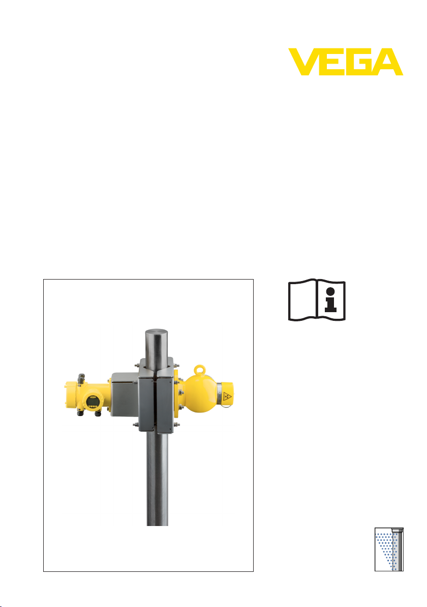
Supplementary instructions
Mounting brackets KV 31
For tubes with ø 50 … 200 mm
Source holder SE 31 / Horizontal sensor mounting
Document ID:
38481
Radiation-based
Page 2

1 Contents
Contents
1 Product description
2 Mounting
3 Supplement
3.1 Technical data . . . . . . . . . . . . . . . . . . . . . . . . . . . . .
3.2 Dimensions . . . . . . . . . . . . . . . . . . . . . . . . . . . . . . .
8
9
Editing status: 2012-02-14
2 Mounting brackets KV 31 • Source holder SE
38481-EN-120228
Page 3
For horizontal sensor
mounting
1 Product description
1 Product description
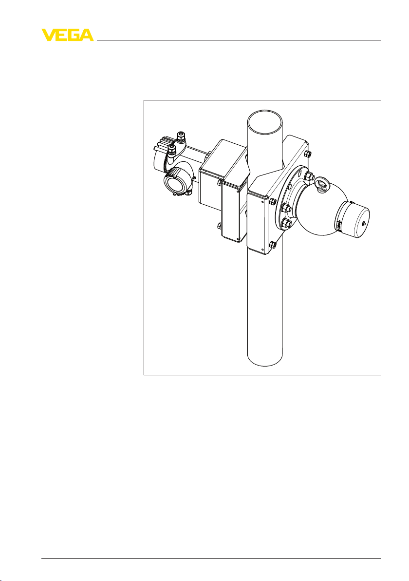
The KV 31 is a mounting bracket for radiation-based measuring
systems. It is suitable for pipes irradiated at right angles.
Fig. 1: Mounting bracket with horizontally mounted sensor
38481-EN-120228
Mounting brackets KV 31 • Source holder SE 3
Page 4
1 2 3
4 65 7 8
1 Product description
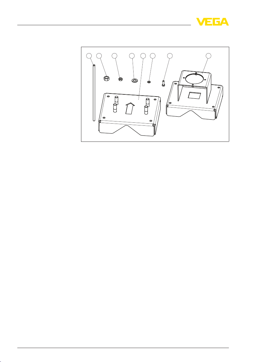
Scope of delivery
The following parts belong to the scope of delivery of KV 31.
Fig. 2: Mounting bracket for pipes irradiated at right angles KV 31 - horizontal
sensor mounting
1 Threaded rod M10 x 360 mm (M10 x 14.17 in) - 4 pcs.
2 Hexagon nut M16 - 4 pcs.
3 Hexagon nut M10 - 16 pcs.
4 Washer for M16 - 4 pieces
5 Clamp - Source holder side (VEGASOURCE 31) - 1 piece
6 Washer for M10 - 8 pieces
7 Hexagon screw M8 - 2 pieces
8 Clamp - Sensor side (MINITRAC) - 1 piece
4 Mounting brackets KV 31 • Source holder SE
38481-EN-120228
Page 5

7 6 8
3 1 4 2
5 A
Operating instructions
2 Mounting
2 Mounting
Take note of the operating instructions of the corresponding sensor
MINITRAC and the source holder VEGASOURCE.
Mounting brackets for
horizontal mounting
Horizontal sensor
mounting
Take note of the following mounting instructions:
l Mount the bracket first, then the sensor and the source holder
l The arrow cutout in the clamp (source container side) and the
transport lug of the source container must point in the same
direction (A) after mounting
l Make sure that the two clamps (5 and 8) of the bracket are in
parallel. Do this by measuring the distances between the clamps
l To avoid injuries, shorten the threaded rods (1) of the brackets to a
suitable length after mounting
Mount the bracket according to the following assembly drawing:
Fig. 3: Mounting bracket with horizontally mounted sensor
1 Threaded rod M10 x 360 mm - 4 pieces
2 Hexagon nut M16 - 4 pcs.
3 Hexagon nut M10 - 16 pcs.
4 Washer for M16 - 4 pieces
5 Clamp - Source holder side (VEGASOURCE 31) - 1 piece
6 Washer for M10 - 8 pieces
7 Hexagon screw M8 - 2 pieces
8 Clamp - Sensor side (MINITRAC) - 1 piece
A Arrow cutout of the clamp and the lug point in the same direction
38481-EN-120228
Mounting brackets KV 31 • Source holder SE 5
Page 6

2 Mounting
Install a protective grid
1 Make sure that the two clamps (5 and 8) of the bracket are in
parallel. Do this by measuring the lateral distances between the
clamps.
2 Tighten the nuts of the threaded rod evenly. Keep the tube
diameter and the stability of the tube material in mind. Avoid
deformation of the tube through an overtightening of the mounting
bracket.
If you have the impression that the tube cannot permanently carry
the weight of the mounting bracket, sensor and source container,
mount a suitable support below the mounting bracket.
3 Shorten the threaded rods after mounting to avoid injuries.
If there are gaps or intervening spaces around the installation, provide
protective fences or grids to keep hands away from the dangerous
area. Such areas must be marked accordingly.
Install a protective grid on both sides of the mounting bracket. A sheet
metal cover or a correspondingly shaped plastic sheet can also be
used.
Corresponding holes for screws of size M5 are provided on the
mounting bracket.
Mount the protective grid according to the following assembly drawing:
6 Mounting brackets KV 31 • Source holder SE
38481-EN-120228
Page 7

M5
1
2
2 Mounting
Fig. 4: Install the protective grid on both sides of the mounting bracket
1 Protective grid
2 Screws M5 - 4 pcs.
38481-EN-120228
Mounting brackets KV 31 • Source holder SE 7
Page 8

3 Supplement
3 Supplement
3.1 Technical data
General data
Take note of the information in the operating instructions manual of the installed MINITRAC level
sensor and the source holder
Material 316L corresponds to 1.4404 or 1.4435
Materials
- Mounting brackets 316L
- Threaded rods 316L
Weight 12.2 kg (26.9 lbs)
Torques
- Screws - Sensor mounting (M8) 15 Nm (11.06 lbf ft)
- Nuts - VEGASOURCE (M16) 20 Nm (14.75 lbf ft)
- Threaded rods (M10) Dependent on the tube material
8 Mounting brackets KV 31 • Source holder SE
38481-EN-120228
Page 9

3.2 Dimensions
279 mm (10.98")
d
268 mm (10.55")302 mm (11.89")
L
31
2
KV 31 - for horizontal sensor mounting
3 Supplement
Fig. 5: Mounting bracket with horizontally mounted sensor
1 Level sensor MINITRAC
2 Mounting bracket - KV 31
3 Source holder VEGASOURCE
L = total length of the measuring system (see following table)
d = tube diameter (see following table)
38481-EN-120228
Mounting brackets KV 31 • Source holder SE 9
Tube DN (in) Tube diameter (d) Total length (L)
DN 50 (2 in) ø 60.3 mm (2.37 in) 672 mm (26.46 in)
DN 100 (4 in) ø 114.3 mm (4.5 in) 737 mm (29.02 in)
DN 125 (5 in) ø 139.7 mm (5.5 in) 770 mm (30.31 in)
DN 150 (6 in) ø 168.3 mm (6.63 in) 803 mm (31.61 in)
Page 10

3 Supplement
Tube DN (in) Tube diameter (d) Total length (L)
DN 175 ø 193.7 mm (7.63 in) 835 mm (32.87 in)
DN 200 (8 in) ø 219.1 mm (8.63 in) 868 mm (34.17 in)
10 Mounting brackets KV 31 • Source holder SE
38481-EN-120228
Page 11

3 Supplement
38481-EN-120228
Mounting brackets KV 31 • Source holder SE 11
Page 12

VEGA Grieshaber KG
ISO 9001
Am Hohenstein 113
77761 Schiltach
Germany
Phone +49 7836 50-0
Fax +49 7836 50-201
E-mail: info.de@vega.com
www.vega.com
Printing date:
All statements concerning scope of delivery, application,
practical use and operating conditions of the sensors and
processing systems correspond to the information avail-
able at the time of printing.
© VEGA Grieshaber KG, Schiltach/Germany 2012
Subject to change without prior notice 38481-EN-120228
 Loading...