

Page 1
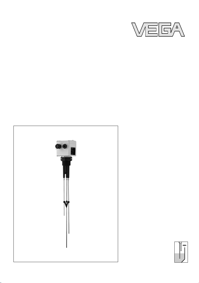
Operating Instructions
VEGAKON 66
with relay
output
Conductive
Page 2

Contents
1 About this document
1.1 Function .
. . . . . . . . . . . . . . . . . . . . . . . . . . . .
4
1.2 Target group . . . . . . . . . . . . . . . . . . . . . . . . . .
4
1.3 Symbolism used . . . . . . . . . . . . . . . . . . . . . . .
4
2 For your safety
2.1 Authorised personnel. . . . . . . . . . . . . . . . . . . .
5
2.2 Appropriate use. . . . . . . . . . . . . . . . . . . . . . . .
5
2.3 Warning about misuse . . . . . . . . . . . . . . . . . . .
5
2.4 General safety instructions . . . . . . . . . . . . . . . .
5
2.5 CE conformity . . . . . . . . . . . . . . . . . . . . . . . . .
5
2.6 Environmental instructions . . . . . . . . . . . . . . . .
6
3 Product description
3.1 Configuration. . . . . . . . . . . . . . . . . . . . . . . . . .
7
3.2 Principle of operation . . . . . . . . . . . . . . . . . . . .
8
3.3 Operation . . . . . . . . . . . . . . . . . . . . . . . . . . . .
9
3.4 Storage and transport . . . . . . . . . . . . . . . . . . .
9
4 Mounting
4.1 General instructions. . . . . . . . . . . . . . . . . . . . .
10
4.2 Mounting information . . . . . . . . . . . . . . . . . . . .
10
5 Connecting to power supply
5.1 Preparing the connection . . . . . . . . . . . . . . . . .
12
5.2 Connection instructions . . . . . . . . . . . . . . . . . .
12
5.3 Wiring plan . . . . . . . . . . . . . . . . . . . . . . . . . . .
12
6 Set up
6.1 General. . . . . . . . . . . . . . . . . . . . . . . . . . . . . .
14
6.2 Adjustment elements . . . . . . . . . . . . . . . . . . . .
14
6.3 Switching point adjustment. . . . . . . . . . . . . . . .
15
6.4 Function chart . . . . . . . . . . . . . . . . . . . . . . . . .
18
7 Maintenance and fault rectification
7.1 Maintenance . . . . . . . . . . . . . . . . . . . . . . . . . .
20
7.2 Electronics exchange. . . . . . . . . . . . . . . . . . . .
20
7.3 Simulation of switching functions . . . . . . . . . . .
21
7.4 Instrument repair . . . . . . . . . . . . . . . . . . . . . . .
21
8 Dismounting
8.1 Dismounting steps. . . . . . . . . . . . . . . . . . . . . .
22
8.2 Disposal . . . . . . . . . . . . . . . . . . . . . . . . . . . . .
22
2 VEGAKON 66 - with relay output
Contents
32649-EN-070615
Page 3

9 Supplement
9.1 Technical data. . . . . . . . . . . . . . . . . . . . . . . . .
23
9.2 Dimensions . . . . . . . . . . . . . . . . . . . . . . . . . . .
26
9.3 Industrial property rights. . . . . . . . . . . . . . . . . .
27
9.4 Trademark . . . . . . . . . . . . . . . . . . . . . . . . . . .
27
VEGAKON 66 - with relay output 3
Contents
32649-EN-070615
Page 4
1 About this document
1.1 Function
This
operating instructions manual provides all the information
you need for mounting, connection and setup as well as
important instructions for maintenance and fault rectification.
Please read this information before putting the instrument into
operation and keep this manual accessible in the immediate
vicinity of the device.
1.2 Target group
This operating instructions manual is directed to trained
personnel. The contents of this manual should be made
available to these personnel and put into practice by them.
1.3 Symbolism used
Information, tip, note
This symbol indicates helpful additional information.
Caution: If this warning is ignored, faults or malfunc-
tions can result.
Warning: If this warning is ignored, injury to persons and/or
serious damage to the instrument can result.
Danger: If this warning is ignored, serious injury to persons
and/or destruction of the instrument can result.
Ex applications
This symbol indicates special instructions for Ex applications.
l List
The dot
set in front indicates a list with no implied sequence.
à Action
This arrow
indicates a single action.
1 Sequence
Numbers set in front indicate successive steps in a procedure.
4 VEGAKON 66 - with relay output
About this document
32649-EN-070615
Page 5

2 For your safety
2.1 Authorised personnel
All
operations described in this operating instructions manual
must be carried out only by trained specialist personnel
authorised by the operator.
During work on and with the device the required personal
protection equipment must always be worn.
2.2 Appropriate use
VEGAKON 66 is a sensor for level detection.
You can find detailed information on the application range in
chapter "Product description".
2.3 Warning about misuse
Inappropriate or incorrect use of the instrument can give rise to
application-specific hazards, e.g. vessel overfill or damage to
system components through incorrect mounting or adjustment.
2.4 General safety instructions
This is a high-tech instrument requiring the strict observance of
standard regulations and guidelines. The user must take note
of the safety instructions in this operating instructions manual,
the country-specific installation standards as well as all
prevailing safety regulations and accident prevention rules.
The instrument must only be operated in a technically flawless
and reliable condition. The operator is responsible for troublefree operation of the instrument.
The user is also obliged to determine, during the entire
duration of use, the compliance of the necessary occupational
safety measures with the current valid regulations and take
note of new regulations.
2.5 CE conformity
VEGAKON 66 is in CE conformity with EMC (89/336/EWG)
and LVD (73/23/EWG).
Conformity has been judged according to the following
standards:
VEGAKON 66 - with relay output 5
For your safety
32649-EN-070615
Page 6

l EMC:
- Emission EN 50081-1
- Susceptibility EN 5008
2-2
l LVD: EN 61010
2.6 Environmental instructions
Protection of the environment is one of our most important
duties. That is why we have introduced an environment
management system with the goal of continuously improving
company environmental protection. The environment management system is certified according to DIN EN ISO 14001.
Please help us fulfil this obligation by observing the environmental instructions in this manual:
l Chapter "Packaging, transport and
storage"
l Chapter "Disposal"
6 VEGAKON 66 - with relay output
For your safety
32649-EN-070615
Page 7
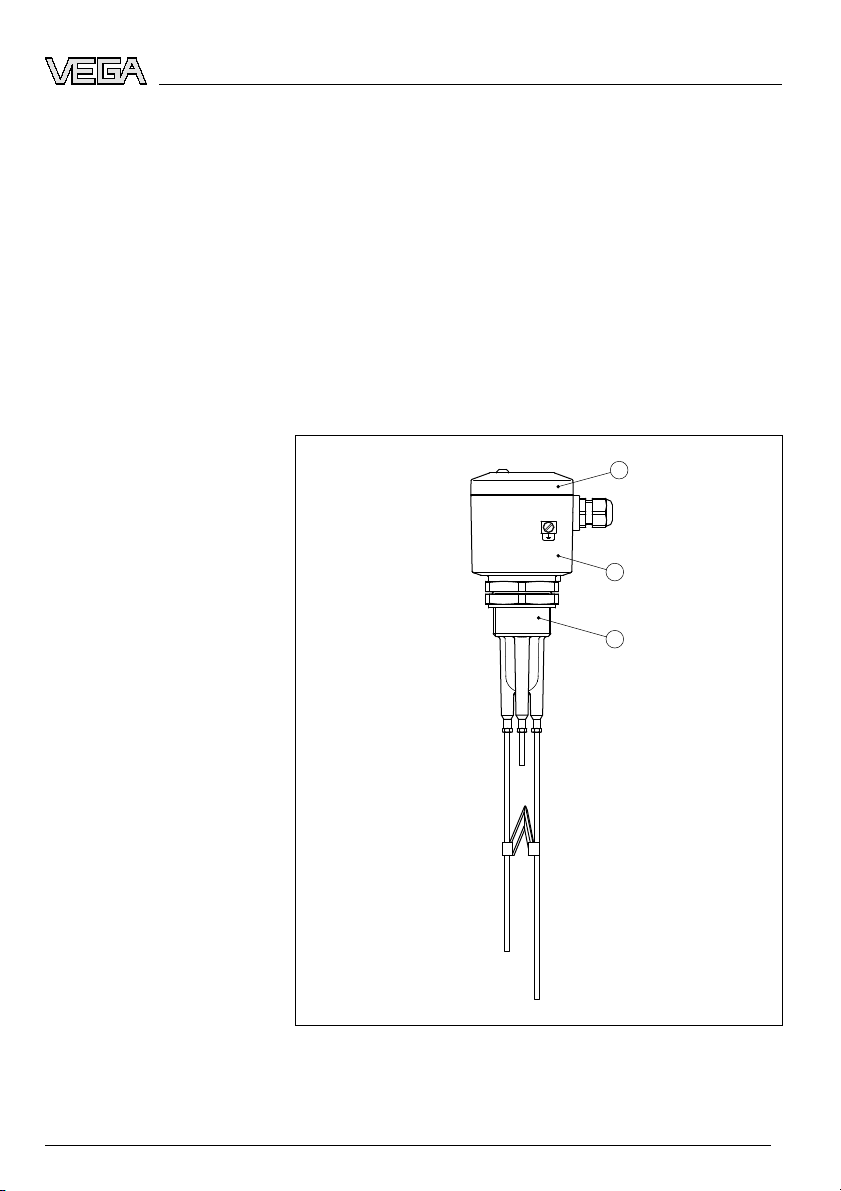
3 Product description
3.1 Configurat
ion
The scope of delivery encompasses:
l VEGAKON 66 compact level
switch
l Documentation
- this operating instructions manual
VEGAKON 66 consists of the following components:
l Housing cover
l Housing with electronics
l P
rocess fitting with electrodes
1
2
3
Fig. 1: VEGAKON 66
1 Housing cover
2 Housing with electronics
3 Process fitting with electrodes
Scope of delivery
Components
VEGAKON 66 - with relay output 7
Product description
32649-EN-070615
Page 8
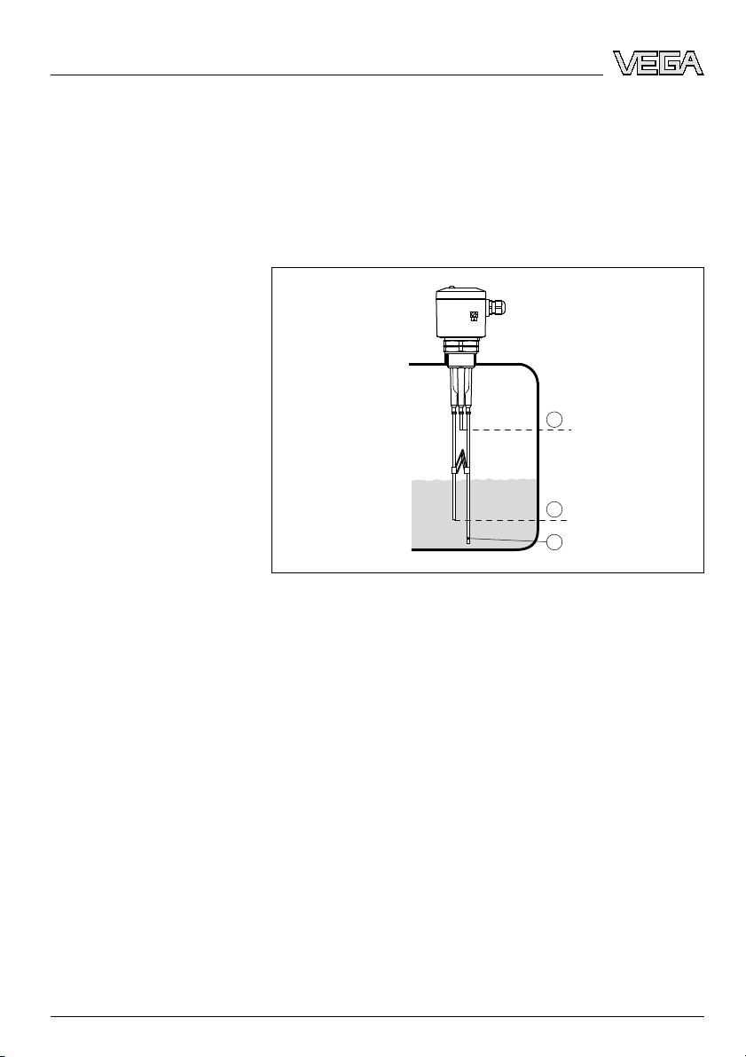
3.2 Principle of operation
The conductive VEGAKON 66 compact level switches detect
levels of conductive liquids.
If at least two electrodes are covered with a conductive
medium, small alternating currents (<1 mA) flow from the
measuring electrode to the ground electrode.
1
3
2
Fig. 2: Functional principle
1 Ground probe
2 Max. level (max. electrode)
3 Min. level (min. electrode)
These alternating currents are measured in respect to their
amplitude and phase position and converted into a switching
command.
VEGAKON 66 can be used for reliable detection of products
over a very wide conductivity and viscosity range.
A level detection can be realised with two measuring electrodes, e.g. a pump or two-point control with three measuring
electrodes.
VEGAKON 66 is a compact instrument, i.e. it can be operated
without external evaluation system. The integrated electronics
evaluates the level signal and outputs a switching signal. With
this switching signal, a connected device can be operated
directly (e.g. a warning system, a PLC, a pump etc.).
The data for power supply are stated in chapter "Technical
data" in the "Supplement".
Area of application
Functional principle
Supply
8 VEGAKON 66 - with relay output
Product description
32649-EN-070615
Page 9

3.3 Operation
The VEGAKON 66 is a compact level switch with integrated
oscillator.
On the electronics module you will find the following indicating
and adjustment elements:
l Control lamp for indication of the switching condition
l Mode changeover for selection of the output signal
l DIL switch for adjustment of the integration time
l Rotary switch for adjustment of the conductivity value
3.4 Stora
ge and transport
Your instrument was protected by packaging during transport.
Its capacity to handle normal loads during transport is assured
by a test according to DIN EN 24180.
The packaging of standard instruments consists of environ-
ment-friendly, recyclable cardboard. In addition, the sensor is
provided with a protective cover of cardboard. For special
versions PE foam or PE foil is also used. Dispose of the
packaging material via specialised recycling companies.
l Storage
and transport temperature see "Supplement -
Technical
data - Ambient conditions"
l Relative humidity 20 … 85 %
Packag
ing
Storage and transport temperature
VEGAKON 66 - with relay output 9
Product description
32649-EN-070615
Page 10

4 Mounting
4.1 General instructions
Use
the recommended cables (see chapter "Connecting to
power supply") and tighten the cable gland.
You can give your VEGAKON 66 additional protection against
moisture penetration by leading the connection cable downward in front of the cable entry. Rain and condensation water
can thus drain off. This applies mainly to mounting outdoors, in
areas where moisture is expected (e.g. by cleaning processes)
or on cooled or heated vessels.
Fig. 3: Measures against moisture penetration
The process fitting must be sealed if there is gauge or low
pressure in the vessel. Before use, check if the seal material is
resistant against the measured product and the process
temperature.
The max. permissible pressure is stated in chapter "Technical
data" in the "Supplement" or on the type label of the sensor.
4.2 Mounting information
Due to agitators, equipment vibration or similar, the probe can
be subjected to strong lateral forces.
During operation, the probe must not touch any installations or
the vessel wall. If necessary, secure the end of the probe
(insulated). Provide a suitable insulated support directly above
the probe end.
Moisture
Pressure/Vacuum
Agitators
10 VEGAKON 66 - with relay output
Mounting
32649-EN-070615
Page 11

1
2
1
2
Fig. 4: Fasten the probe
1 Probe
2 Plastic socket on the probe end
3 Probe
4 Plastic socket laterally mounted
VEGAKON 66 - with relay output 11
Mounting
32649-EN-070615
Page 12

5 Connecting to power supply
5.1 Preparin
g the connection
Always keep in mind the following safety instructions:
l Connect only in the complete absence of line voltage
Connect
the power supply according to the following diagrams.
Oscillator KONE60R is designed in protection class 1. To
maintain this protection class, it is absolutely necessary that
the ground conductor be connected to the internal ground
terminal. Take note of the general installation regulations. As a
rule, connect VEGAKON 66 to vessel ground (PA), or in case
of plastic vessels, to the next ground potential. On the side of
the housing there is a ground terminal between the cable
entries. This connection serves to drain off electrostatic
charges.
The data for power supply are stated in chapter "Technical
data" in the "Supplement".
VEGAKON 66 is connected with standard cable with round
cross section. An outer cable diameter of 5 … 9 mm
(0.2 … 0.35 in) ensures the seal effect of the cable gland.
If cable with a different diameter or wire cross section is used,
exchange the seal or use an appropriate cable connection.
5.2 Connection instructions
Danger:
Switch off power supply before starting connection work.
Connect mains voltage according to the connection diagrams.
5.3 Wiring plan
Is used to switch external voltage sources to relays,
contactors, magnetic valves, horns etc.
Note safety instructions
Select power supply
Selecting connection cable
Floating relay output
12 VEGAKON 66 - with relay output
Connecting to power supply
32649-EN-070615
Page 13

1 2
-
+
L1 N
3 4 5
6 7 8
1
2
Fig. 5: Electronics with relay output
1 Relay output
2 Power supply
VEGAKON 66 - with relay output 13
Connecting to power supply
32649-EN-070615
Page 14

6 Set up
6.1 General
On
the electronics module you will find the following indicating
and adjustment elements:
l DIL switch
for mode adjustment
l DIL switch for adjustment of the integration time
l Rotary switch for adjustment of the conductivity value
l Control lamp for indication of the switching condition
6.2 Adj
ustment elements
876
5
4
3
1
2
max. 250V AC 5A 750VA
max. 250V DC
1A 54W
20...72V DC
20...250V AC
L
N
+ -
R
KON E66R
max
min
K
TEST
0.1
TEST
300
100
30
0.3
1
3
10
A
2s
6s
12s
B
off
off
off
1
27
6
3
45
1 Screwed terminals
2 Signal lamp (LED)
3 Rotary switch: Adjustment of the conductivity value
4 Selection switch: Integration time
5 Selection switch: Mode (A/B) VEGAKON 66
6 Type label
7 Tensile proving ring
The switching condition of the signal lamp can be checked
when the housing is closed. To adjust VEGAKON 66 loosen
the four screws with a wrench on the upper side of the
instrument and remove the housing cover.
Function/Configuration
Signal lamp (2)
14 VEGAKON 66 - with relay output
Set up
32649-EN-070615
Page 15

With the rotary switch you can set the sensitivity of the
instrument. Position 0.1 kΩ is the less sensitive and switch
position 300 kΩ the most sensitive one, see chart "Switching
point adjustment".
There are three switches on the DIL switch block by which you
can adjust the switching on and off delay. Thus prevents, e.g.
the instrument from permanent switching if the level is within
the limits.
The delay refers to the switching status of both relay outputs.
With the switches (2 s, 6 s, 12 s) you can set the integration
time respectively in the range of 0 to 20 seconds. The times of
the activated timers add up. If e.g. the switches 2 s and 12 s
are activated, the integration time will be 14 s.
With the mode adjustment (A/B) you can change the switching
condition of the output. You can set the required mode
according to the "Function chart" (A - max. detection or overfill
protection, B - min. detection or dry run protection).
Loosen the holding screws of the electronics module. Fold the
tensile proving ring upward. With the tensile proving ring you
can pul the electronics module out of the instrument housing.
6.3 Switching point adjustment
Rotary switch position
Switching point at approx. 1 cm covering.
Rotary switch position Conductivity value (medium)
Test max. Switching condition with complete
covering is simulated
0.1 kΩ (insensitive) >6.6 mS
0.3 kΩ >1.7 mS
1 kΩ >540 µS
3 kΩ >180 µS
10 kΩ >54 µS
30 kΩ >20 µS
100 kΩ >5.7 µS
300 kΩ (sensitive) >1.6 µS
Test min. Empty state is simulated
Rotary switch: Adjustment of
the conductivity value (3)
Selection switch: Integration
time (4)
Mode adjustment (5)
Tensile proving ring (7)
VEGAKON 66 - with relay output 15
Set up
32649-EN-070615
Page 16

Examples of conductivity values
Medium Conductivity value Recommended rotary
switch position
Tap water 0.2 mS 3 kΩ
Saltwater (3.5 %) 35 mS 0.1 kΩ
Beer 1.4 mS 1 kΩ
Fruit juice 2 mS 0.3 kΩ
Milk, yogurt 3 mS 0.3 kΩ
Ketchup 15 mS 0.1 kΩ
In case of horizontally mounted instruments, the response
height is determined by the mounting height.
In case of vertically mounted instruments, the response height
is determined by the length of the probe rods.
The modification of the response height by turning the
conductivity value switch is not useful.
To adapt the response height, you can shorten the measuring
rods by sawing them off. Before shortening, unscrew the rods
out of the plastic threaded part of the sensor to avoid
damaging the probe.
The numbers of the rods are visible on the lower side of the
thread.
The ground rod (no. 1) must have the same length or must
even be longer than the longest of the other rods.
The max. rod (no. 2) defines the response height with single
point level switches or the upper switching level with two-point
control. It is the shortest rod.
The min. rod (no. 3) defines the lower switching level, it must
hence be longer than the max. rod. It is not available with
instruments for single point level detection.
The electronics recognises if a min. rod is screwed in and
changes automatically from single to two-point control.
For products with a good conductivity (>3 mS), set the rotary
switch - cnductivity setting (3) generally to switch position 3 kΩ.
Hence the instrument is already completely adjusted.
Take note of the instructions in chart "Examples of conductivity
values". The recommended settings take also influences such
as e.g. condensation or slight buildup into account.
Determination of the response height
Standard setting
16 VEGAKON 66 - with relay output
Set up
32649-EN-070615
Page 17

If there is danger of strong buildup or condensation, you can
set the instrument more insensitive by one rotary switch
position.
The "Function chart" shows how to select the switching
condition of the output.
The following settings apply to products with low conductivity
(<3 mS)
1 Fill the vessel until the shortest probe is covered approx.
1 cm
2 Switch on voltage supply
3 Set the A/B switch to mode A
4 Set the rotary switch to position "TEST min."
5 Turn the rotary switch slowly clockwise until the red LED
lights
The instrument is adapted to the medium, i.e. the relay
denergizes with max. level.
The following settings apply to products with low conductivity
(<3 mS)
1 Empty the vessel until the min. measuring electrode is only
covered approx. 1 cm
2 Switch on voltage supply
3 Set the A/B switch to mode B
4 Set the rotary switch to position "TEST max."
5 Turn the rotary switch slowly anticlockwise until the red
LED lights
The instrument is adapted to the medium, i.e. the relay
deenergized with min. level.
The following settings apply to products with low conductivity
(<3 mS)
1 Fill the vessel until the shortest probe is covered approx.
1 cm
2 Switch on voltage supply
3 Set the A/B switch to mode A
4 Set the rotary switch to position "TEST min."
5 Turn the rotary switch slowly clockwise until the red LED
lights
Level detection for max. signal
Level detection for min. signal
Pump control, A mode
VEGAKON 66 - with relay output 17
Set up
32649-EN-070615
Page 18

The instrument is adapted to the medium, i.e, the relay
deenergizes when the max. level is reached. Only when the
min. probe is decreased, the relay energizes again.
Example: A filling pump is switched on when the min. signal is
decreased, fills the vessels until max. signal is reached and is
then switched off.
The following settings apply to products with low conductivity
(<3 mS)
1 Empty the vessel until the min. measuring electrode is only
covered approx. 1 cm
2 Switch on voltage supply
3 Set the A/B switch to mode B
4 Set the rotary switch to position "TEST max."
5 Turn the rotary switch slowly anticlockwise until the red
LED lights
The instrument is adapted to the medium, i.e. the relay
energizes at max. level. Only of the min. probe is decreased,
the relay denergizes again.
Example: An emptying pump is switched on when the max.
signal is reached, empties the vessels until min. signal is
reached and is then switched off.
In case of several measurement loops (same medium), the
adjustment of one instrument with medium is sufficient. The
determined switch position can be transferred to all other
instruments.
When the conductivity value is known, the switching point
adjustment can be carried out according to the setup in chart
"Rotary switch adjustment".
When exchanging the electronics module, it is sufficient to take
over the setting of the old electronics module.
6.4 Function chart
The following chart provides an overview of the switching
conditions depending on the adjusted mode and level.
Pump control, B mode
Dry adjustment
18 VEGAKON 66 - with relay output
Set up
32649-EN-070615
Page 19

Level Switching sta-
tus, relay module E60R
Control lamp
Mode A
Overflow protec-
tion
1
Relay energized
53 4
(8)(6) (7)
does not light
Mode A
Overflow protec-
tion
2
Relay deener-
gized
53 4
(8)(6) (7)
lights
Mode B
Dry run protection
3
Relay energized
53 4
(8)(6) (7)
does not light
Mode B
Dry run protection
4
Relay deener-
gized
53 4
(8)(6) (7)
lights
Failure of the
supply voltage
(mode A/B)
Relay deener-
gized
53 4
(8)(6) (7)
does not light
1 Max. detection - Vessel empty
2 Max. detection - Vessel full
3 Min. detection - Vessel full
4 Min. detection - Vessel empty
Note:
If VEGAKON 66 is used for oil warning in water, the probe
must be cleaned after having responded to oil (= empty signal)
because otherwise resetting to water will not be ensured
reliably.
VEGAKON 66 - with relay output 19
Set up
32649-EN-070615
Page 20

7 Maintenance and fault rectification
7.1 Maintenance
When
used as directed in normal operation, VEGAKON 66 is
completely maintenance free.
7.2 Electronics exchange
In general, all oscillators of series KONE66 can be inter-
changed. If you want to use an oscillator with a different signal
output, you can download the corresponding operating
instructions manual from our homepage under Downloads.
Proceed as follows:
1 Switch off power supply
2 Unscrew the housing cover
3 Loosen compression fittings with a Phillips screwdriver
4 Pull the connection cables out of the terminals
5 Loosen the two holding screws with a screw driver
(Phillips)
6 Lift tensile proving ring and pull out the old electronics
module
7 Compare the new oscillator with the old one. The type label
of the oscillator must correspond to that of the old
oscillator.
8 Note settings of all adjustment elements of the old
electronics module.
Set the adjustment elements of the new electronics module
to the same settings of the old one.
9 Screw in and tighten the two holding screws with a
screwdriver (Phillips)
10 Insert the wire ends into the open terminals according to
the wiring plan
11 Tighten the screw terminals
12 Check the hold of the wires in the terminals by lightly
pulling on them
13 Check the tightness of the cable entry. The seal ring must
completely encircle the cable.
14 Screw the housing cover back on
The electronics exchange is now finished.
20 VEGAKON 66 - with relay output
Maintenance and fault rectification
32649-EN-070615
Page 21

As soon as you insert the electronics module, VEGAKON 66 is
ready for operation.
7.3 Simulation of switching functions
With the rotary switch for conductivity adjustment, full covering
or empty signal can be simulated.
The filling height must not be changed. You can hence easily
check the response of connected signalling and switching
facilities. Parts of the sensor electronics are also checked
during this test.
The following switch positions, simulate the switching conditions:
l Switch
position "Test
max." full covering (max.)
l Switch position "Test
min." empty signal (min.)
7.4 Instrument repair
If a repair is necessary, please proceed as follows:
You can download a return form (23 KB) from the Internet on
our homepage
www.vega.com under: "Downloads - Forms
and certificates - Repair form".
By doing this you help us carry out the repair quickly and
without having to call back for needed information.
l Print
and fill
out one form per instrument
l Clean the instrument and pack it damage-proof
l Attach the completed form and, if
need be, also a safety
data sheet outside on the packaging
l Please ask the agency serving you for the address of your
return
shipment. You can find the respective agency on our
website
www.vega.com under: "Company - VEGA world-
wide"
VEGAKON 66 - with relay output 21
Maintenance and fault rectification
32649-EN-070615
Page 22

8 Dismounting
8.1 Dismounting steps
Warning:
Before dismounting, be aware of dangerous process conditions such as e.g. pressure in the vessel, high temperatures,
corrosive or toxic products etc.
Take note of chapters "Mounting" and "Connecting to power
supply" and carry out the listed steps in reverse order.
8.2 Disposal
The instrument consists of materials which can be recycled by
specialised recycling companies. We use recyclable materials
and have designed the electronics to be easily separable.
WEEE directive 2002/96/EG
This instrument is not subject to the WEEE directive 2002/96/
EG and the respective national laws (in Germany, e.g.
ElektroG). Pass the instrument directly on to a specialised
recycling company and do not use the municipal collecting
points. These may be used only for privately used products
according to the WEEE directive.
Correct disposal avoids negative effects to persons and
environment and ensures recycling of useful raw materials.
Materials: see chapter "Technical data"
If you cannot dispose of the instrument properly, please
contact us about disposal methods or return.
22 VEGAKON 66 - with relay output
Dismounting
32649-EN-070615
Page 23

9 Supplement
9.1 Technical
data
General data
Material 316L corresponds to 1.4404 or 1.4435
Materials, wetted parts
- Process fitting - thread PP
- Electrode 316Ti
- Process seal Klingersil C-4400
Materials, non-wetted parts
- Housing Plastic PBT (Polyester), Alu die-casting pow-
der-coated
- Temperature adapter 316Ti
- Seal between housing and housing
cover
Silicone
- Ground terminal 316L
Weights
- with plastic housing 550 g (19.4 oz)
- with Aluminium housing 850 g (30 oz)
- Electrode 100 g/m (1.1 oz/ft)
Probe length (L)
- Min. 120 mm (4.7 in)
- Max. 4000 mm (157.5 in)
Process fittings
- Thread G1½ A (PN 25)
Measurement voltage approx. 3 V
eff
Measurement current <3 mA
Output variable
Output Relay output (DPDT), 2 floating spdts
Turn-on voltage
- Min. 10 mV
- Max. 253 V AC, 253 V DC
Switching current
- Min. 10 µA
- Max. 5 A AC, 1 A DC
VEGAKON 66 - with relay output 23
Supplement
32649-EN-070615
Page 24

Breaking capacity
- Min. 50 mW
- Max. 750 VA AC, 54 W DC
If inductive loads or stronger currents are
switched through, the gold plating on the relay
contact surface will be permanently damaged.
The contact is then no longer suitable for
switching low-level signal circuits.
Contact material (relay contacts) AgNi or AgSnO and Au plated
Modes (adjustable)
- A Max. detection or overfill protection
- B Min. detection or dry run protection
Switching delay approx. 0.5 … 20 s
Ambient conditions
Ambient temperature on the housing -40 … +70 °C (-40 … +158 °F)
Ambient temperature with operating
voltage >60 V DC
-40 … +50 °C (-40 … +122 °F)
Storage and transport temperature -40 … +80 °C (-40 … +176 °F)
Process conditions
Permissible process temperature -40 … +100 °C (-40 … +212 °F)
Process pressure -1 … 6 bar/-100 … 600 kPa (-14.5 … 87 psi)
Conductive of the medium min. 5 µS/cm with 30 mm electrode covering
Electromechanical data
Cable gland
- with relay module 1x cable entry M20x1.5; 1x blind stopper
M20x1.5 (cable gland M20x1.5 is attached)
Screw terminals for wire cross-section up to 1.5 mm²
(0.0023 in²)
Voltage supply
Supply voltage 20 … 253 V AC, 50/60 Hz, 20 … 72 V DC (at
U >60 V DC, the ambient temperature can be
max. 50 °C/122 °F)
Power consumption 1 … 9 VA (AC), approx. 1.5 W (DC)
24 VEGAKON 66 - with relay output
Supplement
32649-EN-070615
Page 25

Electrical protective measures
Protection
- Plastic housing IP 66
- Aluminium housing IP 66/IP 67
Overvoltage category II
Protection class I
VEGAKON 66 - with relay output 25
Supplement
32649-EN-070615
Page 26

9.2 Dimensions
L2
L3
L1
~75mm
(2 61/64")
ø 4mm
(5/32")
85mm
(3 11/32")
92,5mm (3
41
/
64
")
24mm
(
15
/
16
")
112mm (4
13
/
32
")
G1½A
SW 60mm
(2 23/64")
M20x1,5
Fig. 21: VEGAKON 66 with three probes
L1 Length ground probe
L2 Length max. probe
L3 Length min. probe
26 VEGAKON 66 - with relay output
Supplement
32649-EN-070615
Page 27

9.3 Industrial property rights
VEGA product lines are global protected by industrial property rights.
Further information see http://www.vega.com.
Only in U.S.A.: Further information see patent label at the sensor housing.
VEGA Produktfamilien sind weltweit geschützt durch gewerbliche Schutzrechte.
Nähere Informationen unter http://www.vega.com.
Les lignes de produits VEGA sont globalement protégées par des droits de
propriété intellectuelle.
Pour plus d'informations, on pourra se référer au site http://www.vega.com.
VEGA lineas de productos están protegidas por los derechos en el campo de la
propiedad industrial.
Para mayor información revise la pagina web http://www.vega.com.
Линии продукции фирмы ВЕГА защищаются по всему миру правами на
интеллектуальную собственность.
Дальнейшую информацию смотрите на сайте http://www.vega.com.
VEGA系列产品在全球享有知识产权保护。
进一步信息请参见网站<http://www.vega.com>。
9.4 Trademark
All brands used as well as trade and company names are
property of their lawful proprietor/originator.
VEGAKON 66 - with relay output 27
Supplement
32649-EN-070615
Page 28

VEGA Grieshaber KG
Am Hohenstein 113
77761 Schiltach
Germany
Phone +49 7836 50-0
Fax +49 7836 50-201
E-mail: info@de.vega.com
www.vega.com
ISO 9001
All statements concerning scope of delivery, application,
practical use and operating conditions of the sensors and
processing systems correspond to the information avail-
able at the time of printing.
© VEGA Grieshaber KG, Schiltach/Germany 2007
Subject to change without prior notice 32649-EN-070615
 Loading...