

Page 1
Ope
rating Instructions
VEGAFLEX 66
-110 … +400 °C
Profibus PA
Guided Micro
wave
Page 2

Content
tent
Con
1 About this document
1.1 Function .
1.2 Target group . . . . . . . . . . . . . . . . . . . . . . . . . .
1.3 Symbolism used . . . . . . . . . . . . . . . . . . . . . . .
2 For your safety
2.1 Authorised personnel. . . . . . . . . . . . . . . . . . . .
2.2 Appropriate use. . . . . . . . . . . . . . . . . . . . . . . .
2.3 Warning about misuse . . . . . . . . . . . . . . . . . . .
2.4 General safety instructions . . . . . . . . . . . . . . . .
2.5 Safety approval markings and safety tips . . . . .
2.6 CE conformity . . . . . . . . . . . . . . . . . . . . . . . . .
2.7 Fulfilling of NAMUR recommendations . . . . . . .
2.8 Safety instructions for Ex areas . . . . . . . . . . . .
2.9 Manufacturer declaration for zone 2 . . . . . . . . .
2.10 Environmental instructions . . . . . . . . . . . . . . . .
3 Product description
3.1 Configuration. . . . . . . . . . . . . . . . . . . . . . . . . .
3.2 Principle of operation . . . . . . . . . . . . . . . . . . . .
3.3 Operation . . . . . . . . . . . . . . . . . . . . . . . . . . . .
3.4 Packaging, transport and storage . . . . . . . . . . .
. . . . . . . . . . . . . . . . . . . . . . . . . . . .
4
4
4
5
5
5
5
6
6
6
7
7
7
8
9
10
11
4 Mounting
4.1 General instructions. . . . . . . . . . . . . . . . . . . . .
4.2 Mounting instructions. . . . . . . . . . . . . . . . . . . .
5 Connecting to power supply
5.1 Preparing the connection . . . . . . . . . . . . . . . . .
5.2 Connection steps - Instrument housing . . . . . . .
5.3 Wiring plan, single chamber housing. . . . . . . . .
5.4 Wiring plan, double chamber housing . . . . . . . .
5.5 Wiring plan - version IP 66/IP 68, 1 bar. . . . . . .
6 Set up with the indicating and adjustment module
PLICSCOM
6.1 Short description . . . . . . . . . . . . . . . . . . . . . . .
6.2 Insert indicating and adjustment module . . . . . .
6.3 Adjustment system . . . . . . . . . . . . . . . . . . . . .
6.4 Setup procedure . . . . . . . . . . . . . . . . . . . . . . .
6.5 Menu schematic . . . . . . . . . . . . . . . . . . . . . . .
2 VEG
12
13
18
19
20
22
24
25
25
27
28
35
AFLEX 66 • Profibus PA
32764-EN-080716
Page 3
Content
7 Setup
with PACTware and other adjustment programs
7.1 Connecting the PC . . . . . . . . . . . . . . . . . . . . .
7.2 Parameter adjustment with PACTware . . . . . . .
7.3 Parameter adjustment with PDM. . . . . . . . . . . .
7.4 Saving the parameter adjustment data . . . . . . .
8 Maintenance and fault rectification
8.1 Maintenance . . . . . . . . . . . . . . . . . . . . . . . . . .
8.2 Remove interferences . . . . . . . . . . . . . . . . . . .
8.3 Exchanging the electronics module. . . . . . . . . .
8.4 Instrument repair . . . . . . . . . . . . . . . . . . . . . . .
9 Dismounting
9.1 Dismounting steps . . . . . . . . . . . . . . . . . . . . . .
9.2 Disposal . . . . . . . . . . . . . . . . . . . . . . . . . . . . .
10 Supplement
10.1 Technical data. . . . . . . . . . . . . . . . . . . . . . . . .
10.2 Profibus PA . . . . . . . . . . . . . . . . . . . . . . . . . . .
10.3 Dimensions . . . . . . . . . . . . . . . . . . . . . . . . . . .
10.4 Industrial property rights. . . . . . . . . . . . . . . . . .
10.5 Trademark . . . . . . . . . . . . . . . . . . . . . . . . . . .
37
37
38
38
39
39
41
42
44
44
45
55
60
64
64
Supplementary documentation
Information:
Supplemen
tary documents appropriate to the ordered version
come with the delivery. You can find them listed in chapter
"Product description".
Instructions manuals for accessories and replacement
parts
Tip:
ensure reliable setup and operation of your VEGAFLEX 66,
To
we offer accessories and replacement parts. The associated
documents are:
l 27720 - VEGADIS 61
l 30207 - Electronics
l 31088 - Flanges
l 30391 - Spacer
32764-EN-080716
VEGAFLEX 66 • Profibus PA 3
module VEGAFLEX series 60
according to DIN-EN-ASME-JIS-GOST
Page 4
1 Abou
t this document
1 Abo
ut this document
1.1 Function
This
operating instructions manual provides all the information
you need for mounting, connection and setup as well as
important instructions for maintenance and fault rectification.
Please read this information before putting the instrument into
operation and keep this manual accessible in the immediate
vicinity of the device.
1.2 Target group
This operating instructions manual is directed to trained
personnel. The contents of this manual should be made
available to these personnel and put into practice by them.
1.3 Symbolism used
Information, tip, no
This symbol indicates helpful additional information.
Caution: If
tions can result.
Warning: If this warning is ignored, injury to persons and/or
serious damage to the instrument can result.
Danger: If this warning is ignored, serious injury to persons
and/or destruction of the instrument can result.
this warning is ignored, faults or malfunc-
te
applications
Ex
This symbol indicates special instructions for Ex applications.
l List
The dot set in front indicates a list with no implied sequence.
à Action
This arrow
1 Sequence
Numbers set in front indicate successive steps in a procedure.
4 VEG
indicates a single action.
32764-EN-080716
AFLEX 66 • Profibus PA
Page 5

2 For
your safety
2 For
your safety
2.1 Authorised personnel
All
operations described in this operating instructions manual
must be carried out only by trained specialist personnel
authorised by the plant operator.
During work on and with the device the required personal
protection equipment must always be worn.
2.2 Appropriate use
VEGAFLEX 66 is a sensor for continuous level measurement.
You can find detailed information on the application range in
chapter "Product description".
Operational reliability is ensured only if the instrument is
properly used according to the specifications in the operating
instructions manual as well as possible supplementary
instructions.
For safety and warranty reasons, any invasive work on the
device beyond that described in the operating instructions
manual may be carried out only by personnel authorised by the
manufacturer. Arbitrary conversions or modifications are
explicitly forbidden.
2.3 Warning about misuse
Inappropriate or incorrect use of the instrument can give rise to
application-specific hazards, e.g. vessel overfill or damage to
system components through incorrect mounting or adjustment.
2.4 General safety instructions
This is a high-tech instrument requiring the strict observance of
standard regulations and guidelines. The user must take note
of the safety instructions in this operating instructions manual,
the country-specific installation standards as well as all
prevailing safety regulations and accident prevention rules.
The instrument must only be operated in a technically flawless
and reliable condition. The operator is responsible for troublefree operation of the instrument.
32764-EN-080716
VEGAFLEX 66 • Profibus PA 5
Page 6

2 For
your safety
the entire duration of use, the user is obliged to
During
determine the compliance of the required occupational safety
measures with the current valid rules and regulations and also
take note of new regulations.
2.5 Safety approval markings and safety tips
The safety approval markings and safety tips on the device
must be observed.
2.6 CE conformity
The protection goals of the EMC Directive 2004/108/EC (EMC)
and the Low Voltage Directive 2006/95/EC (LVD) are fulfilled.
Conformity has been judged according to the following
standards:
EMC: EN 61326-1: 2006
(electrical instruments for control technology and laboratory
use - EMC requirements)
l Emission: Class B
l Susceptibil
ity: Industrial
LVD: EN 61010-1: 2001
(safety regulations for electrical measurement, control and
laboratory instruments - part 1: General requirements)
areas
2.7 Fulfilling of NAMUR recommendations
With respect to interference resistance and emitted interference, the NAMUR recommendation NE 21 is fulfilled.
With respect to compatibility, the NAMUR recommendation
NE 53 is fulfilled. This applies also to the corresponding
indicating and adjustment components. VEGA instruments are
generally upward and downward compatible.
l Sensor
l DTM VEGAFLEX 66 for adjustment software PACTware
l Indicating and adjustment module for sensor software
software for DTM
The parameter adjustment of the basic sensor functions is
independent of the software version. The range of available
functions depends on the respective software version of the
individual components.
The software version of VEGAFLEX 66 can be determined as
follows:
6 VEG
VEGAFLEX 66 HART, PA or FF
32764-EN-080716
AFLEX 66 • Profibus PA
Page 7

your safety
2 For
l via PACTware
the type label of the electronics
l on
l via the indicating and adjustment module
You can
view all software histories on our website www.vega.
com. Make use of this advantage and get registered for update
information via e-mail.
2.8 Safety instructions for Ex areas
Please note the Ex-specific safety information for installation
and operation in Ex areas. These safety instructions are part of
the operating instructions manual and come with the Exapproved instruments.
2.9 Manufacturer declaration for zone 2
In conformity with DIN EN 60079-15/2005 VEGAFLEX 66 is
suitable for use in zone 2.
The operator must use the instrument as it was intended to be
used and follow the specifications of the following documents:
l this operating instructions manual
l the manufacturer declaration 32906 (download
"www.vega.com")
l the
applicable installation regulations
under
2.10 Environ
mental instructions
Protection of the environment is one of our most important
duties. That is why we have introduced an environment
management system with the goal of continuously improving
company environmental protection. The environment management system is certified according to DIN EN ISO 14001.
Please help us fulfil this obligation by observing the environmental instructions in this manual:
l Chapter "Packaging, transport and
l Chapter "Disposal"
32764-EN-080716
VEGAFLEX 66 • Profibus PA 7
storage"
Page 8

3 Produc
t description
Scope of delivery
Components
3 Prod
3.1 Configurat
uct description
ion
The scope of delivery encompasses:
l VEGAFLEX 66 level sensor
l Documentation
- this
operating instructions manual
- Operating instructions manual 27835 "Indicating and
adjustment module PLICSCOM" (optional)
- Supplementary instructions manual 31708 "Heating for
indicating and adjustment module" (optional)
- Supplementary instructions manual "Plug connector for
continuously measuring sensors" (optional)
- Ex-specific "Safety instructions" (with Ex-versions)
- if necessary, further certificates
VEGAFLEX 66 consists of the following components:
with
l Process fitting
l Housing with electronics
l Housing cover, optionally
probe
available with indicating and
adjustment module
8 VEG
32764-EN-080716
AFLEX 66 • Profibus PA
Page 9
1
2
3
3 Produc
t description
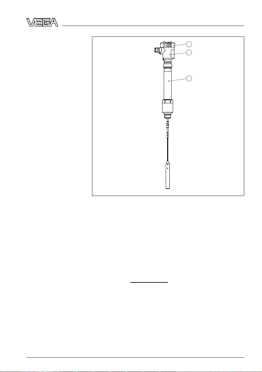
version with plastic housing
ation
Type label
Fig. 1: VEGAFLEX 66 - cable
1 Housing cover with integrated indicating and adjustment module (optional)
2 Housing with electronics
3 Process fitting
The type label contains the most important data for identi-
fication and use of the instrument:
l Article number
l Serial number
l Technical data
l Article numbers, document
With the serial number, you can access the delivery data of the
instrument via "
www.vega.com", "VEGA
Tools" and "serial
number search". In addition to the type label outside, you can
also find the serial number on the inside of the instrument.
3.2 Principle of operation
Application range
32764-EN-080716
VEGAFLEX 66 • Profibus PA 9
VEGAFLEX 66 is a level sensor with coax, rod or cable probe
for continuous level measurement in non-conductive products
with temperatures of -110 … +400 °C (-166 … +752 °F).
Page 10

3 Produc
t description
is designed for industrial use in all areas of process
It
technology and can be used in non-conductive liquids.
Functional principle
Power supply and bus
communication
GSD/EDD
High frequency microwave pulses are guided along a steel
rope or a rod. Upon reaching the product surface, the
microwave pulses are reflected. The running time is evaluated
by the instrument and outputted as distance.
Power supply via the Profibus DP/PA segment coupler or
VEGALOG 571 EP cards. A two-wire cable according to
Profibus specification serves as carrier of both power and
digital data signals for multiple sensors. The instrument profile
of VEGAFLEX 66 corresponds to profile specification version
3.0.
The GSD (instrument master files) and bitmap files necessary
for planning your Profibus-DP-(PA) communication network
are available from the download section on the VEGA
homepage
www.vega.com
under "Services - Downloads -
Software - Profibus". There you can also find the appropriate
certificates. In a PDM environment, an EDD (Electronic Device
Description) is also required to enable the full range of sensor
functions (also available as a download).A CD with the
appropriate files can be ordered via e-mail under info@de.
vega.com or by phone from one of the VEGA agencies under
the order number "DRIVER.S".
The optional heating requires its own power supply. You can
find further details in the supplementary instructions manual
"Heating for indicating and adjustment module".
3.3 Operation
VEGAFLEX 66 can be adjusted with different adjustment
media:
l with indicating and adjustment module
l with the suitable VEGA
DTM in
adjustment software according to the FDT/DTM standard,
e.g. PACTware and PC
l with the adjustment program PDM
The
entered
parameters are generally saved in VEGAFLEX
66, optionally also in the indicating and adjustment module or
in PACTware.
10 VEG
conjunction with an
32764-EN-080716
AFLEX 66 • Profibus PA
Page 11

3 Produc
t description
Packaging
Transport
Transport inspection
Storage
Storage and transport
temperature
3.4 Pack
aging, transport and storage
Your instrument was protected by packaging during transport.
Its capacity to handle normal loads during transport is assured
by a test according to DIN EN 24180.
The packaging of standard instruments consists of environ-
ment-friendly, recyclable cardboard. For special versions, PE
foam or PE foil is also used. Dispose of the packaging material
via specialised recycling companies.
Transport must be carried out under consideration of the notes
on the transport packaging. Nonobservance of these instructions can cause damage to the device.
The delivery must be checked for completeness and possible
transit damage immediately at receipt. Ascertained transit
damage or concealed defects must be appropriately dealt
with.
Up to the time of installation, the packages must be left closed
and stored according to the orientation and storage markings
on the outside.
Unless otherwise indicated, the packages must be stored only
under the following conditions:
l Not
l Dry and dust free
l Not exposed to corrosive media
l P
l Avoiding mechanical shock and vibration
l Storage and transport temperature see "Supplement -
l Relative humidity 20 … 85 %
in the open
rotected against solar radiation
Technical
data - Ambient conditions"
32764-EN-080716
VEGAFLEX 66 • Profibus PA 11
Page 12
4 M
ounting
Mounting position
Welding work
Handling
Moisture
4 Mou
nting
4.1 General instructions
Select
an installation position you can easily reach for
mounting and connecting as well as later retrofitting of an
indicating and adjustment module. The housing can be rotated
by 330° without the use of any tools. You can also install the
indicating and adjustment module in four different positions
(each displaced by 90°).
Before beginning the welding work, remove the oscillator
(electronics) from the sensor. By doing this, you avoid damage
to the electronics through inductive coupling.
With threaded versions, the housing must not be used to screw
in the instrument! Applying tightening forces on the housing
can damage its internal parts.
Use the hexagon for screwing in.
Use the recommended cables (see chapter "Connecting to
power supply") and tighten the cable gland.
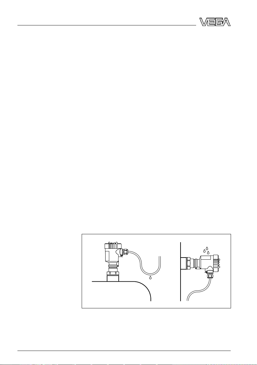
You can give your instrument additional protection against
moisture penetration by leading the connection cable downward in front of the cable entry. Rain and condensation water
can thus drain off. This applies mainly to outdoor mounting as
well as installation in areas where high humidity is expected (e.
g. through cleaning processes) or on cooled or heated
vessels.
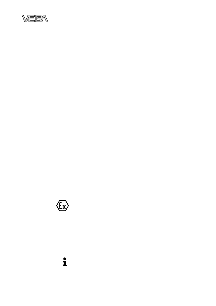
Measuring range
Fig. 2: Measures
The reference plane for the measuring range of the sensors is
against moisture penetration
the sealing surface of the thread or flange.
12 VEG
32764-EN-080716
AFLEX 66 • Profibus PA
Page 13

ounting
4 M
in mind that a min. distance must be maintained below
Keep
the reference plane and possibly also at the end of the probe measurement in these areas is not possible (dead band). Keep
in mind that the cable length cannot be used all the way to the
end because measurement in the area of the gravity weight is
not possible. These min. distances (dead bands) are listed in
chapter "Technical data".
Pressure
Mounting position
The process fitting must be sealed if there is gauge or low
pressure in the vessel. Before use, check if the seal material is
resistant against the measured product and the process
temperature.
The max. permissible pressure is specified in chapter
"Technical data" or on the type label of the sensor.
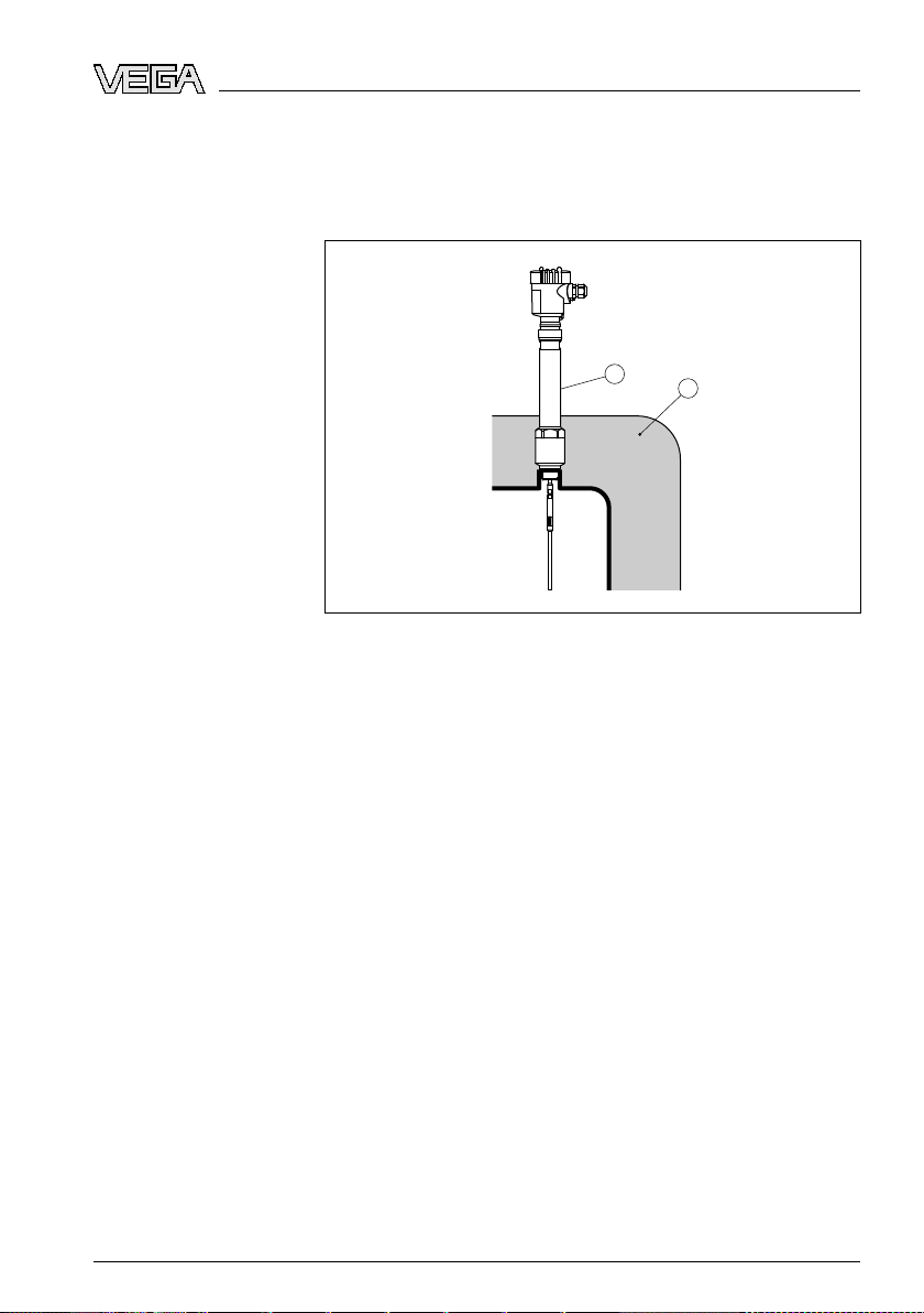
4.2 Mounting instructions
Mount VEGAFLEX 66 in such a way that the distance to vessel
installations or to the vessel wall is at least 300 mm (12 in).
During operation, the probe must not touch any installations or
the vessel wall. If necessary, fasten the probe end.
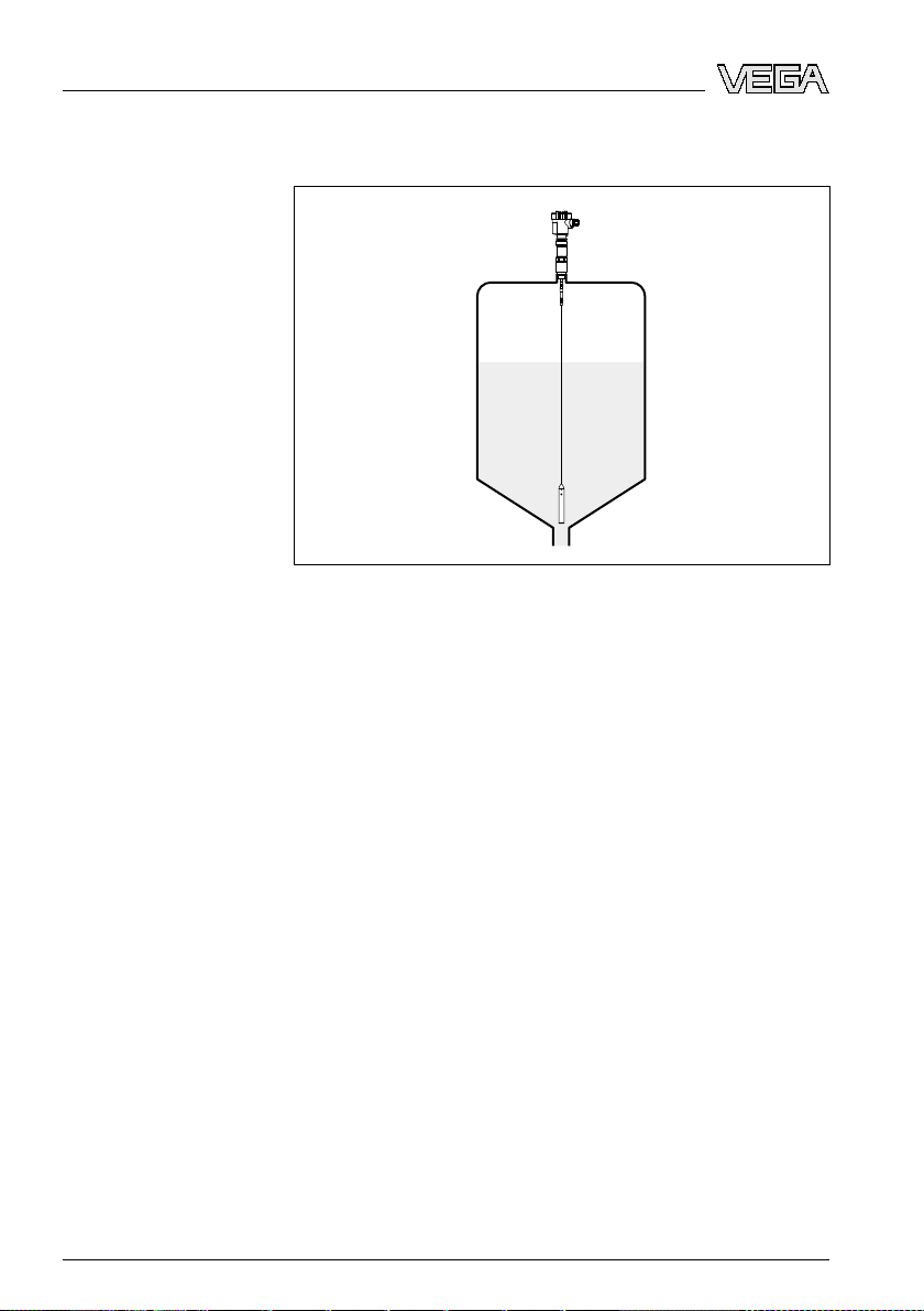
In vessels with conical bottom it can be advantageous to
mount the sensor in the center of the vessel, as measurement
is then possible down to the lowest point of the bottom. When
using the cable version, keep in mind that measurement down
to the tip of the probe is not possible. The exact value of the
32764-EN-080716
VEGAFLEX 66 • Profibus PA 13
Page 14
4 M
ounting
Standpipes or bypass
tubes
min. distance (lower
dead band) is stated in chapter "Technical
data".
Fig. 3: Vessel
with conical bottom
Standpipes or bypass tubes are normally metal tubes with a
diameter of 30 … 200 mm (1.18 … 7.87 in). In measurement
technology such a tube corresponds to a coax probe. It does
not matter if the standpipe is perforated or slotted for better
mixing. Lateral inlets with bypass tubes also do not influence
the measurement.
Measuring probes can be mounted in bypass tubes up to
DN 200.
The max. temperature is 250 °C (482 °F).
If VEGAFLEX 66 is used in standpipes or bypass tubes,
contact with the tube wall should be avoided. We offer spacers
as accessories for fastening the probe in the middle of the
tube.
Depending on the tube diameter or tube length, one or several
spacers can be mounted. With cable probes, the cable can
also be strained to avoid contact with the tube.
The max. temperature for the spacers is 250 °C (482 °F).
A special high temperature version of VEGAFLEX 66 with
integrated bypass tube can be used in applications with
temperatures up to 400 °C (752 °F).
32764-EN-080716
14 VEG
AFLEX 66 • Profibus PA
Page 15
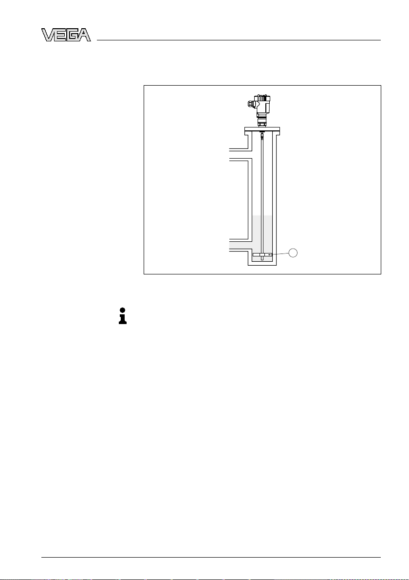
in mind that buildup can form on the spacers. Strong
1
Keep
buildup can influence the measurement.
4 M
ounting
Fig. 4: Position
1 Spacer
of the spacer
Note:
Measureme
nt in a standpipe is not recommended for very
adhesive products.
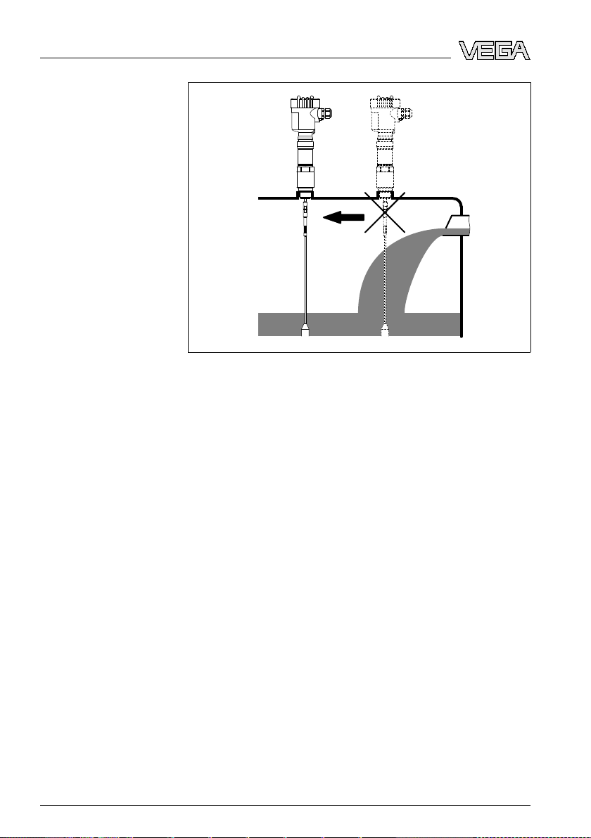
Inflowing medium
Make sure that the probe is not subjected to strong lateral
forces. Mount VEGAFLEX 66 at a position in the vessel where
no disturbances, e.g. from filling openings, agitators, etc., can
occur.
32764-EN-080716
VEGAFLEX 66 • Profibus PA 15
Page 16
4 M
ounting
Fixing
Heat insulation
Fig. 5: Lateral
load
Excessive system vibration or shocks, e.g. caused by agitators
or turbulence in the vessel (e.g. from fluidisation) can cause
the coax probe of VEGAFLEX 66 to vibrate in resonance.
Should a coax probe of more than 1 m (3.281 in) length should
be used, you can provide a suitable support or guy directly
above the end of the probe to stabilise it.
If there is a danger of the probe touching the vessel wall during
operation due to product movements or agitators etc., the
measuring probe should be securely fixed.
In the gravity weight there is a thread (M12), e.g. for a ring bolt
(article no. 2.27424).
Make sure that the probe cable is not completely taut. Avoid
tensile loads on the cable.
Avoid undefined cable-vessel connections, i.e. the connection
must be either grounded reliably or isolated reliably. Any
deviation from this requirement can lead to measurement
errors.
VEGAFLEX 66 should be integrated in the vessel installation.
This prevents the electronics from strong heating by heat
radiation.
32764-EN-080716
16 VEG
AFLEX 66 • Profibus PA
Page 17
1
2
ounting
4 M
sure that with heated vessels the permissible ambient
Make
temperature on the housing is not exceeded. The permissible
ambient temperature is stated in chapter "Technical data"
under "Ambient conditions".
Fig. 6: Vessel
1 Heat insulation
2 Ambient temperature on the housing
32764-EN-080716
VEGAFLEX 66 • Profibus PA 17
with heat insulation
Page 18
ecting to power supply
5 Conn
Note safety instructions
Take note of
safety instructions for Ex applications
Select power supply
Selecting connection
cable
5 Con
5.1 Preparin
necting to power supply
g the connection
Always keep in mind the following safety instructions:
l Connect only in the complete absence of line voltage
l If overvoltage surges are expected, overvoltage
arresters
should be installed according to Profibus specifications
Tip:
We
recommend VEGA overvoltage arrester B63-32.
In
hazardous areas you should take note of the appropriate
regulations, conformity and type approval certificates of the
sensors and power supply units.
Power is supplied via a Profibus DP/PA segment coupler or a
VEGALOG 571 EP input card. The power supply range can
differ depending on the instrument version.
Data for power supply are specified in chapter "Technical
data".
Connection is made with screened cable according to the
Profibus specification. Power supply and digital bus signal are
carried over the same two-wire connection cable.
Use cable with round cross-section. A cable outer diameter of
5 … 9 mm (0.2 … 0.35 in) ensures the seal effect of the cable
gland. If you are using cable with other diameter or crosssection, you have to exchange the seal or use a suitable cable
gland.
Please make sure that your installation is carried out according
to the Profibus specification. In particular, make sure that the
termination of the bus is done with appropriate terminating
resistors.
Cable gland ½ NP T
On the instrument with cable entry ½ NPT and plastic housing
there is a metallic ½" threaded insert moulded into the plastic
housing.
18 VEG
32764-EN-080716
AFLEX 66 • Profibus PA
Page 19
ecting to power supply
5 Conn
Caution:
grease should be used when screwing the NPT cable
No
gland or steel tube into the threaded insert. Standard grease
can contain additives that corrode the connection between
threaded insert and housing. This would influence the stability
of the connection and the tightness of the housing.
Cable screening and
grounding
Select connection cable for Ex
applications
In systems with potential equalisation, connect the cable
screen directly to ground potential at the power supply unit, in
the connection box and at the sensor. The screen in the sensor
must be connected directly to the internal ground terminal. The
ground terminal outside on the housing must be connected to
the potential equalisation (low impedance).
In systems without potential equalisation, connect the cable
screen directly to ground potential at the power supply unit and
at the sensor. In the connection box or T-distributor, the screen
of the short stub to the sensor must not be connected to
ground potential or to another cable screen. The cable screens
to the power supply unit and to the next distributor must be
connected to each other and also connected to ground
potential via a ceramic capacitor (e.g. 1 nF, 1500 V). The low
frequency potential equalisation currents are thus suppressed,
but the protective effect against high frequency interference
signals remains.
total capacitance of the cable and of all capacitors must
The
not exceed 10 nF in Ex applications.
note of the corresponding installation regulations for Ex
Take
applications. In particular, make sure that no potential equalisation currents flow over the cable screen. In case of
grounding on both sides this can be achieved by the use of a
capacitor or a separate potential equalisation.
5.2 Connection steps - Instrument housing
Proceed as follows:
1 Unscrew the housing cover
2 If an indicating and adjustment module is installed, remove
it by turning it slightly to the left.
3 Loosen compression nut of the cable entry
32764-EN-080716
VEGAFLEX 66 • Profibus PA 19
Page 20
ecting to power supply
5 Conn
4 Remove
approx. 10 cm (4 in) of the cable mantle, strip
approx. 1 cm (0.4 in) insulation from the ends of the
individual wires
5 Insert the cable through the cable gland into the sensor
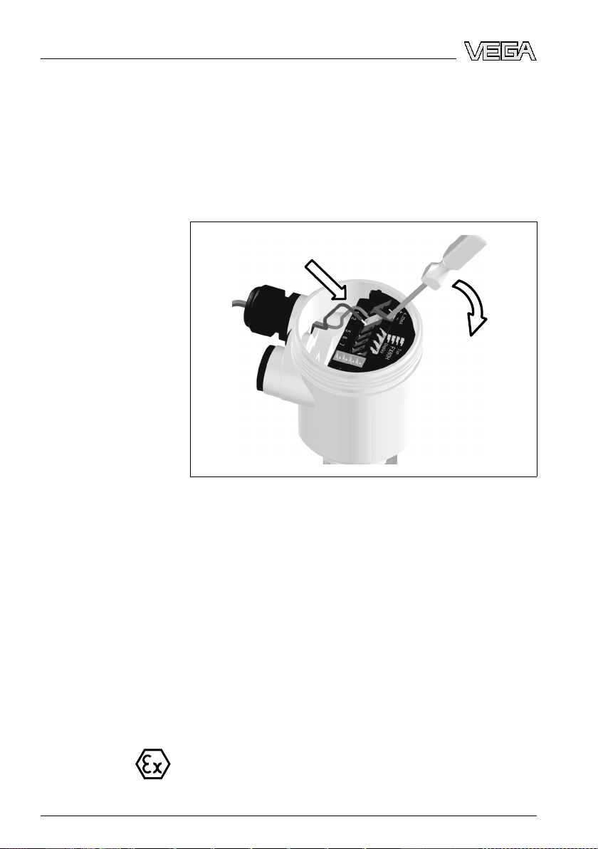
6 Lift the opening levers of the terminals with a screwdriver
(see following illustration)
7 Insert the wire ends into the open terminals according to
the wiring plan
Fig. 7: Connection
steps 6 and 7
8 Press down the opening levers of the terminals, you will
hear the terminal spring closing
9 Check the hold of the wires in the terminals by lightly
pulling on them
10 Connect the screen to the internal ground terminal, connect
the outer ground terminal with potential equalisation
11 Tighten the compression nut of the cable entry. The seal
ring must completely encircle the cable
12 Screw the housing cover on
The electrical connection is finished.
5.3 Wiring plan, single chamber housing
following illustrations apply to the non-Ex as well as to the
The
Ex-ia version.
20 VEG
32764-EN-080716
AFLEX 66 • Profibus PA
Page 21
5
5
5
5
1 2
4
3
I²C
Display
1 2 5 6 7 8
3
4
1
2
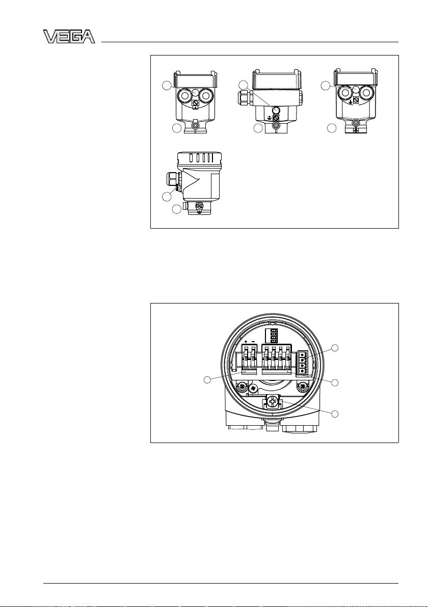
Housing overview
ecting to power supply
5 Conn
Electronics and connection compartment
Fig. 8: Material
1 Plastic
2 Aluminium
3 Stainless steel, investment casting
4 Stainless steel, electro-polished
5 Filter element for air pressure compensation of all material versions. Blind
stopper with version IP 66/IP 68, 1 bar for Aluminium and stainless steel
Fig. 9: Electronics
1 Plug connector for VEGACONNECT (I²C interface)
2 Spring-loaded terminals for connection of the external indication VEGADIS
61
3 Ground terminal for connection of the cable screen
4 Spring-loaded terminals for voltage supply
versions, single chamber housing
and connection compartment, single chamber housing
32764-EN-080716
VEGAFLEX 66 • Profibus PA 21
Page 22
I2C
Display
1
1 2 5
6 7 8
1 2 3
4
5
ecting to power supply
5 Conn
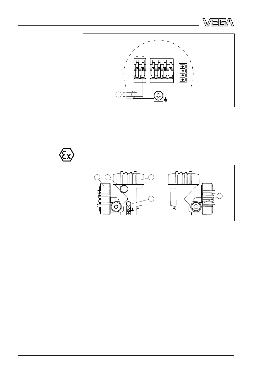
Wiring plan
Housing overview
Fig. 10: Wiring
1 Voltage supply/Signal output
plan, single chamber housing
5.4 Wiring plan, double chamber housing
The
following illustrations apply to the non-Ex as well as to the
Ex-ia version.
Fig. 11: Double
1 Housing cover, connection compartment
2 Blind stopper or plug M12 x 1 for VEGADIS 61 (optional)
3 Housing cover, electronics compartment
4 Filter element for air pressure compensation
5 Cable gland
chamber housing
22 VEG
32764-EN-080716
AFLEX 66 • Profibus PA
Page 23
1
3
2
Display
1 2 5 6 7 8
I2C
3
1
2
Display
1 2
I²C
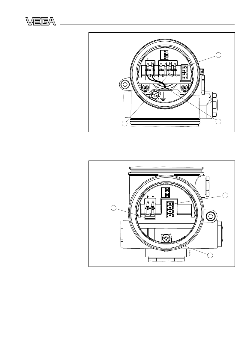
Electronics compartment
ecting to power supply
5 Conn
Connection compartment
Fig. 12: Electronics
1 Plug connector for VEGACONNECT (I²C interface)
2 Internal connection cable to the connection compartment
3 Terminals for VEGADIS 61
Fig. 13: Connection
1 Plug connector for VEGACONNECT (I²C interface)
2 Ground terminal for connection of the cable screen
3 Spring-loaded terminals for voltage supply
compartment, double chamber housing
compartment, double chamber housing
32764-EN-080716
VEGAFLEX 66 • Profibus PA 23
Page 24
I2C
1
1 2
+
-
1
2
ecting to power supply
5 Conn
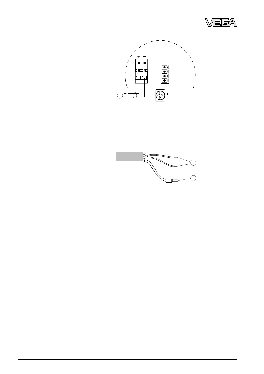
Wiring plan
Wire assignment, con-
nection cable
Fig. 14: Wiring
1 Voltage supply/Signal output
plan, double chamber housing
5.5 Wiring plan - version IP 66/IP 68, 1 bar
Fig. 15: Wire
1 brown (+) and blue (-) to power supply or to the processing system
2 Shielding
assignment, connection cable
24 VEG
32764-EN-080716
AFLEX 66 • Profibus PA
Page 25

up with the indicating and adjustment module PLICSCOM
6 Set
Function/Configuration
Mount/Dismount indicat-
ing and adjustment
module
6 Set
up with the indicating and
adjustment module PLICSCOM
6.1 Short description
The
indicating and adjustment module is used for measured
value display, adjustment and diagnosis. It can be mounted in
the following housing versions and instruments:
sensors of the plics
l All
well as in the double chamber housing (optionally in the
electronics or connection compartment)
l External
From
indicating and adjustment unit VEGADIS 61
a hardware version …- 01 or higher of PLICSCOM as
well as a hardware version …- 01, 03 or higher of the
corresponding sensor, an integrated backlight can be switched
on via the adjustment menu. The hardware version is stated on
the type label of the PLICSCOM or the sensor electronics.
Note:
You
can find detailed information on the adjustment in the
operating instructions manual "Indicating and adjustment
module".
6.2 Insert indicating and adjustment module
The indicating and adjustment module can be inserted into the
sensor and removed again at any time. It is not necessary to
interrupt the power supply.
Proceed as follows:
1 Unscrew the housing cover
2 Place the indicating and adjustment module in the desired
position on the electronics (you can choose any one of four
different positions - each displaced by 90°)
3 Press the indicating and adjustment module onto the
electronics and turn it to the right until it snaps in.
4 Screw housing cover with inspection window tightly back
on
Removal is carried out in reverse order.
The indicating and adjustment module is powered by the
sensor, an additional connection is not necessary.
®
instrument family, in the single as
32764-EN-080716
VEGAFLEX 66 • Profibus PA 25
Page 26

up with the indicating and adjustment module PLICSCOM
6 Set
Fig. 16: Installation
of the indicating and adjustment module
Note:
If
you intend to retrofit the instrument with an indicating and
adjustment module for continuous measured value indication,
a higher cover with an inspection glass is required.
32764-EN-080716
26 VEG
AFLEX 66 • Profibus PA
Page 27

1.1
2
3
1
up with the indicating and adjustment module PLICSCOM
6 Set
Key functions
Adjustment system
6.3 Adj
Fig. 17: Indicating
1 LC display
2 Indication of the menu item number
3 Adjustment keys
l [OK] key:
ustment system
and adjustment elements
- Move
to
the menu overview
- Confirm selected menu
- Edit parameter
- Save
l [->] key to select:
- menu
value
change
- list entry
- Select
l [+] key:
editing position
- Change value of the parameter
l [ESC] key:
- interrupt input
- jump
The sensor is adjusted via the four keys of the indicating and
adjustment module. The LC display indicates the individual
menu items. The functions of the individual keys are shown in
the above illustration. Approx. 10 minutes after the last
pressing of a key, an automatic reset to measured value
indication is triggered. Any values not confirmed with [OK] will
not be saved.
to the next higher menu
32764-EN-080716
VEGAFLEX 66 • Profibus PA 27
Page 28

up with the indicating and adjustment module PLICSCOM
6 Set
Switch on phase
Address setting
Parameter adjustment
6.4 Setup
procedure
After VEGAFLEX 66 is connected to voltage supply or after
voltage recurrence, the instrument carries out a self-check for
approx. 30 seconds. The following steps are carried out:
l Internal
l Indication of the instrument type, the firmware
check of the electronics
as well as
the sensor TAGs (sensor designation)
l Status byte goes briefly to fault value
Then the current measured value will be displayed and the
corresponding digital output signal will be outputted to the
1)
cable.
Before starting the actual parameter adjustment of a P
rofibus
PA sensor, the address setting must first be carried out. You
will find a detailed description in the operating instructions
manual of the indicating and adjustment module or in the
online help of PACTware or DTM.
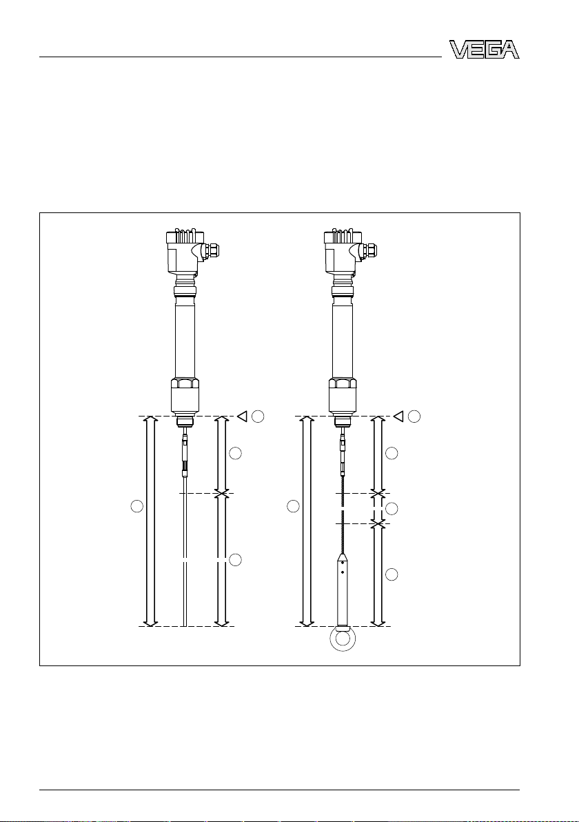
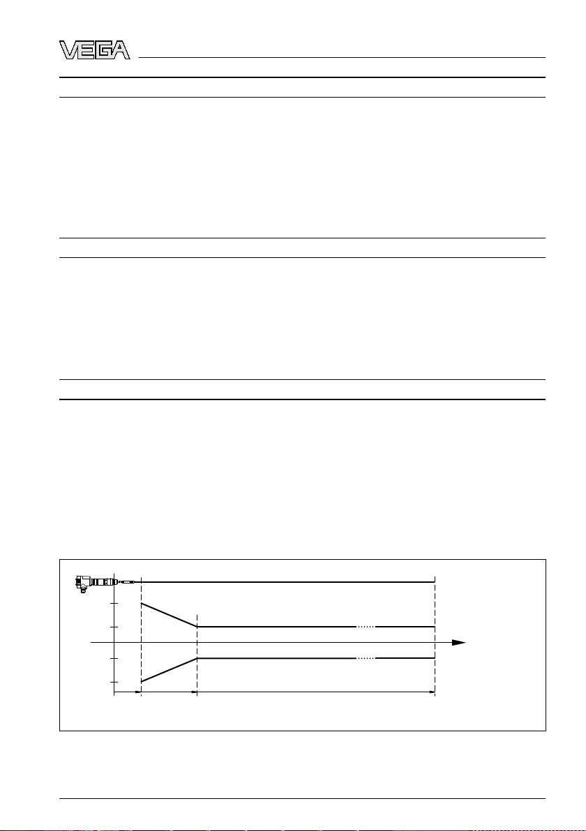
As VEGAFLEX 66 is a distance measuring instrument, the
distance from the sensor to the product surface is measured.
To have the real product level displayed, an allocation of the
measured distance to the percentage height must be made. To
carry out this adjustment, the distance is entered with full and
empty vessel. If these values are not known, an adjustment
with the distance values, e.g. 10 % and 90 % is also possible.
Starting point for these distance specifications is always the
seal surface of the thread or flange. With these settings, the
real level is calculated. Furthermore the operating range of the
sensor is limited from maximum to the required range.
The real product level during this adjustment is not important,
because the min./max. adjustment is always carried out
without changing the product level. These settings can be
made ahead of time without the instrument having to be
installed.
In the main menu item "Basic adjustment", the individual
submenu items should be selected one after the other and
provided with the correct parameter values.
Caution:
there is a separation of different liquids in the vessel, e.g. by
If
condensation, VEGAFLEX 66 will always detect the medium
with the higher dielectric figure (ε
1)
The values correspond to the actual measured level as well as to the settings already carried out, e.g. default setting.
28 VEG
).
r
32764-EN-080716
AFLEX 66 • Profibus PA
Page 29

up with the indicating and adjustment module PLICSCOM
6 Set
in mind that interfaces can cause faulty measurements.
Keep
If you want to measure the total height of both liquids reliably,
please contact our service department or use an instrument
specially designed for interface measurement.
Start your parameter adjustment with the following menu items
of the basic adjustment:
Carrying out min. adjustment
Carrying out max. adjustment
Proceed as follows:
1 Move from the measured value display to the main menu
by pushing [OK].
▶
Basic adjustment
Display
Diagnostics
Service
Info
2 Select the menu item "Basic adjustment" with [->] and
confirm with [OK]. Now the menu item "Min. adjustment" is
displayed.
Min. adjustment
0.00 %
=
10.000 m(d)
8.000 m(d)
3 Prepare the % value for editing with [OK] and set the
cursor to the requested position with [->]. Set the
requested percentage value with [+] and save with [OK].
The cursor jumps now to the distance value.
4 Enter the suitable distance value in m for the empty vessel
(e.g. distance from the sensor to the vessel bottom)
corresponding to the percentage value.
5 Save the settings with [OK] and move to "Max. adjustment"
with [->].
Proceed as follows:
Max. adjustment
100.00 %
=
1.000 m(d)
2.000 m(d)
1 Prepare the % value for editing with [OK] and set the
cursor to the requested position with [->]. Set the
requested percentage value with [+] and save with [OK].
The cursor jumps now to the distance value.
32764-EN-080716
VEGAFLEX 66 • Profibus PA 29
Page 30

up with the indicating and adjustment module PLICSCOM
6 Set
Application
2 Enter
the appropriate distance value in m (corresponding
to the percentage value) for the full vessel. Keep in mind
that the max. level must lie below the dead band.
3 Save the settings with [OK].
Each product has different reflective properties. In addition,
there are various interfering factors which have to be taken into
account: agitated product surfaces and foam generation (with
liquids); dust generation, material cones and echoes from the
vessel wall (with solids). To adapt the sensor to these different
conditions, you should first select in this menu item under
"Medium" the selection "Liquid" or "Solid".
With coax versions, this menu item must be set to "Liquid".
Application
Liquid
Standard
(DK ≥ 2)
Depending on the dielectric figure (dielectri value or εr),
measured products can have a different reflective property.
Therefore an additional selection possibility is available.
Under "Sensitivity" you can select "Standard (DK ≥ 2)" or
"Increased sensitivity (DK < 2)".
Through this, the sensor is adapted perfectly to the product
and measurement reliability, particularly in products with bad
reflective properties, is considerably increased.
Enter the requested parameter via the appropriate keys, save
your settings and jump to the next menu item with the [->] key.
Damping
To suppress fluctuations in the measured value display, e. g.
caused by an agitated product surface, an integration time can
be set. This time can be between 0 and 999 seconds. Keep in
mind that the reaction time of the entire measurement will then
be longer and the sensor will react to measured value changes
with a delay. In general, a period of a few seconds is sufficient
to smooth the measured value display.
Damping
0 s
Enter the requested parameter via the appropriate keys, save
your settings and jump to the next menu item with the [->] key.
30 VEG
32764-EN-080716
AFLEX 66 • Profibus PA
Page 31

up with the indicating and adjustment module PLICSCOM
6 Set
Linearisation curve
A linearization
is necessary for all vessels in which the vessel
volume does not increase linearly with the level - e. g. with a
cylindrical or spherical tank - and the indication or output of the
volume is required. Corresponding linearization curves are
preprogrammed for these vessels. They represent the
correlation between the level percentage and vessel volume.
By activating the appropriate curve, the volume percentage of
the vessel is displayed correctly. If the volume should not be
displayed in percent but e.g. in l or kg, a scaling can be also
set in the menu item "Display".
Linearisation curve
linear
Enter the requested parameter via the appropriate keys, save
your settings and jump to the next menu item with the [->] key.
Caution:
Note
the following, if VEGAFLEX 66 is used as part of an
overfill protection system according to WHG:
If a linearisation curve is selected, the measuring signal is no
longer compulsorily linear proportional to the level. This must
be taken into consideration by the user, particularly when
adjusting the switching point on the level switch.
Sensor-TAG
In this menu item you can enter an unambiguous designation
for the sensor, e.g. the measurement loop name or the tank or
product designation. In digital systems and in the documentation of larger plants, a singular designation should be entered
for exact identification of individual measuring sites.
Sensor-TAG
Sensor
With this menu item, the Basic adjustment is finished and you
can now jump to the main menu with the [ESC] key.
Gating out of false signals
High sockets or vessel installations, such as e. g. struts or
agitators as well as buildup and weld joints on the vessel walls
cause interfering reflections which can impair the measurement. A false echo storage detects and marks these false
echoes, so that they are no longer taken into account for the
32764-EN-080716
VEGAFLEX 66 • Profibus PA 31
Page 32

up with the indicating and adjustment module PLICSCOM
6 Set
level measurement. A fals
e echo memory should be created
with empty vessel so that all potential interfering reflections will
be detected.
Probes in coax version require no gating out of false echoes
since they are not influenced by false reflections.
Gating out of false signals
Change now?
Proceed as follows:
1 Move from the measured value display to the main menu
by pushing [OK].
2 Select the menu item "Service" with [->] and confirm with
[OK]. Now the menu item "False signal suppression" is
displayed.
3 Confirm "False signal suppression - Change now" with
[OK] and select in the below menu "Create new". Enter the
actual distance from the sensor to the product surface. All
false signals in this area are detected by the sensor and
saved after confirming with [OK].
Note:
Check
the distance to the product surface, because if an
incorrect (too large) value is entered, the existing level will be
saved as false signal. The filling level would then no longer be
detectable in this area.
Copy
sensor data
This function enables reading out parameter adjustment data
as well as writing parameter adjustment data into the sensor
via the indicating and adjustment module. A description of the
function is available in the operating instructions manual
"Indicating and adjustment module".
The following data are read out or written with this function:
l Measured
l Adjustment
l Medium
l Vessel form
l Damping
l Linearisation curve
l Sensor-TAG
l Display
l Unit of measurement
32 VEG
value presentation
ed value
32764-EN-080716
AFLEX 66 • Profibus PA
Page 33
up with the indicating and adjustment module PLICSCOM
6 Set
l Language
l Sensitivity
l PA scaling unit
l PV-Out-Scale
l Channel
l Additional PA value
The following safety-relevant data are not read out or written:
l HART mode
l PIN
l SIL
l Sensor length/Sens
l Gating out of false signals
Copy sensor data
Copy sensor data?
or type
Reset
Basic adjustment
If the function "Reset" is carried out, the sensor resets the
values of the following menu items to the reset values (see
2)
chart):
following values will be reset:
The
Function Reset
Max. adjustment Distance, upper dead zone
Min. adjustment Distance, supplied sensor length
Min. adjustment - Cable version Distance, lower dead zone
Integration time ti 0 s
Linearisation linear
Sensor-TAG Sensor
Display PA-Out 1
Channel (PV) lin %
Additional PA value (PV) lin %
Out-Scale-Unit %
PV-Out-Scale 0.00 lin % = 0.0 %
value
100.0 lin % = 100 %
The values of the following menu items are not reset to the
reset values (see chart) with "Reset":
2)
Sensor-specific basic adjustment.
32764-EN-080716
VEGAFLEX 66 • Profibus PA 33
Page 34

up with the indicating and adjustment module PLICSCOM
6 Set
Optional settings
Function Reset
Sensor address no reset
Language no reset
value
Factory setting
Like basic adjustment, furthermore special parameters are
reset to default values.
3)
Pointer
The
min. and max. distance values are reset to the actual
value.
Additional adjustment and diagnosis options such as e.g.
scaling, simulation or trend curve presentation are shown in
the following menu schematic. You will find a detailed
description of these menu items in the operating instructions
manual "Indicating and adjustment module".
3)
Special parameters are parameters which are set customer-specifically on
the service level with the adjustment software PACTware.
34 VEG
32764-EN-080716
AFLEX 66 • Profibus PA
Page 35
up with the indicating and adjustment module PLICSCOM
6 Set
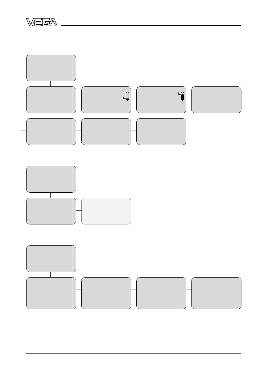
Basic adjustment
▶
Basic adjustment
Display
Diagnostics
Service
Info
Sensor address
000
Channel
PV lin. value
Display
Basic adjustment
▶
Display
Diagnostics
Service
Info
Displayed value
Primary Value
1.1
1.5
2.1
1
2
6.5 Menu
Min. adjustment
0.00 %
=
10.000 m(d)
8.000 m(d)
Damping
0 s
Lighting
Switched off
▼
schematic
1.2
1.6
2.4
Max. adjustment
100.00 %
=
1.000 m(d)
2.000 m(d)
Sensor-TAG
Sensor
1.3
1.7
Linearisation curve
linear
1.4
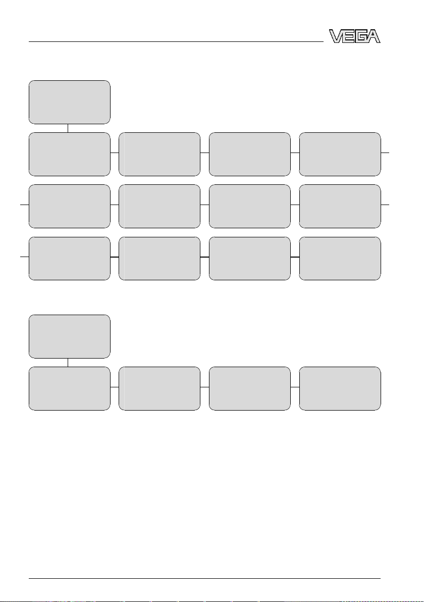
Diagnostics
Basic adjustment
Display
▶
Diagnostics
Service
Info
Pointer
Distance min.: 0.580 m(d)
Dist. max.: 16.785 m(d)
32764-EN-080716
VEGAFLEX 66 • Profibus PA 35
3.1
3
Sensor status
OK
3.2
Curve selection
Echo curve
3.3
Echo curve
Presentation of the echo
curve
3.4
Page 36
up with the indicating and adjustment module PLICSCOM
6 Set
Service
Basic adjustment
Display
Diagnostics
▶
Service
Info
4
Sensor
5 m
Rod
Out-Scale-Unit
Unit of measurement
Info
Basic adjustment
Display
Diagnostics
Service
▶
Info
Sensor type
Serial number
12345678
Volume
hl
m(d)
select?
4.1
4.5
4.9
5.2
5
Application
Liquid
Standard
(DK ≥ 2)
PV-Out-Scale
0 % = 0.0 m³
100 % = 100 m³
Language
Deutsch
Date of manufacture
4. July 2007
Software version
3.50
4.2
4.6
4.10
5.2
Gating out of false signals
Change now?
Simulation
Start simulation?
Copy sensor data
Copy sensor data?
Last change using PC
4. July 2007
4.3
4.7
4.11
5.3
Additional PA value
Secondary Value 1
Reset
Select reset?
PIN
Enable?
Sensor characteristics
Display now?
4.4
4.8
4.12
5.5
36 VEG
32764-EN-080716
AFLEX 66 • Profibus PA
Page 37
~
=
Power supply
VEGACONNECT 3
TM
>PA<
2
3
1
7 Setup
with PACTware and other adjustment programs
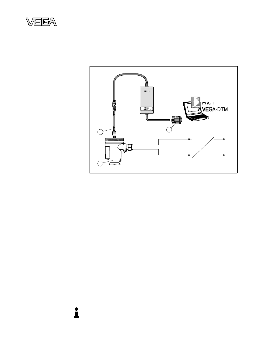
Connection via I²C interface
7 Setup
with PACTware and other
adjustment programs
7.1 Connect
Fig. 18: Connection
1 RS232 connection
2 VEGAFLEX 66
3 I²C adapter cable for VEGACONNECT 3
Necessary components:
l VEGAFLEX 66
l PC with PACTware and
l VEGACONNECT 3 with I²C adapter cable (article no.
2.27323)
l Power supply unit
ing the PC
of the PC directly to the sensor via I²C interface
suitable VEGA DTM
32764-EN-080716
VEGAFLEX 66 • Profibus PA 37
7.2 Parameter adjustment with PACTware
Further setup steps are described in the operating instructions
manual "DTM Collection/PACTware" attached to each CD and
which can also be downloaded from our homepage. A detailed
description is available in the online help of PACTware and the
VEGA DTMs.
Note:
Keep
in mind that for setup of VEGAFLEX 66, DTM-Collection
in the actual version must be used.
Page 38

7 Setup
with PACTware and other adjustment programs
currently available VEGA DTMs are provided in the DTM
All
Collection on CD and can be obtained from the responsible
VEGA agency for a token fee. This CD includes also the up-to-
date PACTware version. The basic version of this DTM
Collection incl. PACTware is also available as a free-of-charge
download from the Internet.
Go via
www.vega.com
and "Downloads" to the item "Soft-
ware".
7.3 Parameter adjustment with PDM
For VEGA sensors, instrument descriptions for the adjustment
program PDM are available as EDD. The instrument descriptions are already implemented in the current version of PDM.
For older versions of PDM, a free-of-charge download is
available via Internet.
www.vega.com
Go via
and "Downloads" to the item "Soft-
ware".
7.4 Saving the parameter adjustment data
It is recommended to document or save the parameter
adjustment data. They are hence available for multiple use or
service purposes.
The VEGA DTM Collection and PACTware in the licensed,
professional version provide suitable tools for systematic
project documentation and storage.
38 VEG
32764-EN-080716
AFLEX 66 • Profibus PA
Page 39

aintenance and fault rectification
8 M
Reaction when malfunctions occur
Causes of malfunction
Fault rectification
8 Main
tenance and fault rectification
8.1 Maintenance
When
used in the correct way, no special maintenance is
required in normal operation.
8.2 Remove interferences
The operator of the system is responsible for taken suitable
measures to remove interferences.
A maximum of reliability is ensured. Nevertheless, faults can
occur during operation. These may be caused by the following,
e.g.:
l Sensor
l Process
l Voltage supply
l Signal processing
The first
as well as to evaluate the error messages via the indicating
and adjustment module. The procedure is described below.
Further comprehensive diagnostics can be carried out on a PC
with the software PACTware and the suitable DTM. In many
cases, the causes can be determined in this way and faults
can be rectified.
measures to be taken are to check the output signals
24 hour service hotline
However, should these measures not be successful, call the
VEGA service hotline in urgent cases under the phone no. +49
1805 858550.
The hotline is available to you 7 days a week round-the-clock.
Since we offer this service world-wide, the support is only
available in the English language. The service is free of
charge, only the standard telephone costs will be charged.
Checking Profibus PA
? When an additional instrument is connected, the segment
fails.
l Max. supply
current
of the segment coupler exceeded
à Measure the current consumption, reduce size of
segment
32764-EN-080716
VEGAFLEX 66 • Profibus PA 39
Page 40

aintenance and fault rectification
8 M
? Wrong
presentation of the measured value in Simatic S5
l Simatic S5 cannot
interpret the number format IEEE of
the measured value
à Insert converting component from Siemens
? In Simatic S7 the measured value is always presented as 0
l Only four bytes are consistently loaded in the PLC
à Use
function component SFC 14 to load 5 bytes
consistently
? Measured value on the indicating and adjustment module
does not correspond to the value in the PLC
l The menu item "Display - Display
value" is not set to
"PA-Out"
à Check values and correct, if necessary
? No connection between PLC and PA network
l Incorrect adjustment of the bus parameter and the
segment
coupler-dependent baud rate
à Check data and correct, if necessary
? Instrument does not appear during connection setup
l Profibus DP cable
à Check
l Incorrect termination
cable and correct, if necessary
pole-reversed
à Check termination at the beginning and end points of
the bus and terminate, if necessary, according to the
specification
l Instrum
ent not connected to the segment, double
assignment
of an address
à Check and correct, if necessary
applications, the regulations for the wiring of intrinsically
In Ex
safe circuits must be observed.
Fault messages via the
indicating/adjustment
module
? E013
l no measured value available
à sensor in
boot phase
à Sensor does not find an echo, e.g. due to faulty
installation or wrong parameter adjustment
à Wrong sensor length entered
40 VEG
32764-EN-080716
AFLEX 66 • Profibus PA
Page 41
aintenance and fault rectification
8 M
? E017
l Adjustment span too small
à Carry out a fresh adjustment and increase the distance
between min. and max. adjustment
? E036
l no operable sensor software
à Carry out
a software update or send the instrument for
repair
? E042/E043
l Hardware error, electro
nics defective
à Exchange instrument or return instrument for repair
? E113
l Communi
à Exchange
cation conflict
instrument or return instrument for repair
Reaction after fault rectification
Depending on the failure reason and measures taken, the
steps described in chapter "Set up" must be carried out again,
if necessary.
8.3 Exchanging the electronics module
Preparations
32764-EN-080716
VEGAFLEX 66 • Profibus PA 41
If the electronics module is defective, it can be replaced by the
user.
applications only one oscillator with respective Ex
In Ex
approval may be used.
If there is no electronics module available on site, one can be
ordered from the agency serving you.
The new oscillator must contain the order data of the sensor.
These can be loaded as follows:
the factory by VEGA
l At
l Or on site by the user
Information:
When
loading on site, first of all the order data must be
downloaded from the Internet (see operating instructions
manual "Oscillator").
Page 42

aintenance and fault rectification
8 M
both cases, the serial number of VEGAFLEX 66 is required.
In
The serial numbers are stated on the type label of VEGAFLEX
66, on the inner wall of the housing or on the delivery note.
Assignment
Profibus PA
Return of rod versions
The oscillators are adapted to the respective sensor and differ
in their signal output or in their power supply. You can find a
suitable oscillator in the following overview.
Electronics module FX-E.60P suitable for VEGAFLEX 61, 62,
63, 65, 66 - Profibus PA:
hout
l FX-E.60PX (X = wit
l FX-E.60PA (A = approvals CA, DA according to product
approvals)
list)
l FX-E.60PC (C = approvals XM, CX, CM, CK, GX
according to product list)
8.4 Instrument repair
If a repair is necessary, please proceed as follows:
You can download a return form (23 KB) from our Internet
homepage
certificates - Repair form".
By doing this you help us carry out the repair quickly and
without having to call back for needed information.
l Print
l Clean the instrument and pack it damage-proof
l Attach the completed form and probably the safety data
sheet outside on the packaging
l Please ask the agency serving you for the address of your
return
website
wide"
On instruments with exchangeable rod, the rod must be
unscrewed for transport to avoid damages.
Return the parts separately for repair.
To loosen to rod, you require a fork spanner with wrench size
8.
1 Loosen the rod on the flat surfaces with a fork spanner
(SW 8), provide counterforce with another fork spanner
(SW 8)
2 Twist off the loosened rod manually
www.vega.com
and fill
out one form per instrument
under: "Downloads - Forms and
shipment. You can find the respective agency on our
www.vega.com
under: "Company - VEGA world-
32764-EN-080716
42 VEG
AFLEX 66 • Profibus PA
Page 43

aintenance and fault rectification
8 M
also chapter "Maintenance and fault rectification"/
See
"Exchange cable/rod"
32764-EN-080716
VEGAFLEX 66 • Profibus PA 43
Page 44

9 Dismoun
ting
9 Dism
ounting
9.1 Dismounting steps
Warning:
Before dismounting, be aware of dangerous process conditions such as e.g. pressure in the vessel, high temperatures,
corrosive or toxic products etc.
Take note of chapters "Mounting" and "Connecting to power
supply" and carry out the listed steps in reverse order.
9.2 Disposal
The instrument consists of materials which can be recycled by
specialised recycling companies. We use recyclable materials
and have designed the electronics to be easily separable.
WEEE directive 2002/96/EG
This instrument is not subject to the WEEE directive 2002/96/
EG and the respective national laws. Pass the instrument
directly on to a specialised recycling company and do not use
the municipal collecting points. These may be used only for
privately used products according to the WEEE directive.
Correct disposal avoids negative effects to persons and
environment and ensures recycling of useful raw materials.
Materials: see chapter "Technical data"
If you have no possibility to dispose of the old instrument
professionally, please contact us concerning return and
disposal.
44 VEG
32764-EN-080716
AFLEX 66 • Profibus PA
Page 45

10 Sup
plement
10 Sup
plement
10.1 Technical data
General
Material 316L corresponds to 1.4404 or 1.4435
Materials, wetted parts
- Process fitting - coax version 316L and Aluminium oxide-ceramic 99.7 %
- Process fitting - rod version 316L and Aluminium oxide-ceramic 99.7 %
- Process fitting - cable version 316L and Aluminium oxide-ceramic 99.7 %
- Tube: ø 21.3 mm (0.839 in) 316L or Hastelloy C22 (2.4602)
- Rod: ø 6 mm (0.236 in) 316L or Hastelloy C22 (2.4602)
- Cable: ø 4 mm (0.157 in) 316 (1.4401)
- Process seal on the instrument side
- Process seal On site (instruments with thread: Klingersil
Materials, non-wetted parts
- Plastic housing plastic PBT (Polyester)
- Aluminium die-casting housing Aluminium die-casting AlSi10Mg, powder-
- Stainless steel housing - precision
- Stainless steel housing, electropol-
- Seal between housing and housing
- Inspection window in housing cover
- Ground terminal 316L
data
(cable/rod leadthrough)
casting
ished
cover
(optional)
(Al₂O₃), Hastelloy C22 (2.4602) and Aluminium oxide-ceramic 99.7 % (Al₂O₃)
(Al₂O₃), Hastelloy C22 (2.4602) and Aluminium oxide-ceramic 99.7 % (Al₂O₃)
(Al₂O₃)
graphite
C-4400 is attached)
coated - basis: Polyester
316L
316L
NBR (stainless steel housing, investment
casting), silicone (Aluminium/plastic housing,
stainless steel housing, electro-polished)
Polycarbonate
Process fittings
- Pipe thread, cylindrical (ISO 228 T1) G¾ A, G1 A, G1½ A
- American pipe thread, tapered ¾ NPT, 1 NPT, 1½ NPT
- Flanges DIN from DN 25, ANSI from 1"
32764-EN-080716
VEGAFLEX 66 • Profibus PA 45
Page 46

10 Suppl
ement
Weight
- Instrument
weight (depending on
approx. 0.8 … 8 kg (0.176 … 17.64 lbs)
process fitting)
- Tube: ø 21.3 mm (0.839 in) approx. 920 g/m (9.9 oz/ft)
- Rod: ø 6 mm (0.236 in) approx. 220 g/m (2.365 oz/ft)
- Cable: ø 4 mm (0.157 in) approx. 80 g/m (0.86 oz/ft)
- Gravity weight approx. 325 g (11.5 oz)
Sensor length L (from seal surface)
- Tube: ø 21.3 mm (0.839 in) 0.3 … 6 m (0.984 … 19.69 ft)
- Trimming accuracy - tube < 1 mm (0.039 in)
- Rod: ø 6 mm (0.236 in) 0.3 … 4 m (0.984 … 13.12 ft)
- Trimming accuracy - rod < 1 mm (0.039 in)
- Cable: ø 4 mm (0.157 in) 1 … 32 m (3.281 … 105 ft)
- Trimming accuracy - cable ±0.05 %
Lateral load
- Tube: ø 21.3 mm (0.839 in) 60 Nm (44 lbf ft)
- Rod: ø 6 mm (0.236 in) 4 Nm (3 lbf ft)
Max. tensile load with cable: ø 4 mm
2.5 KN (562 lbf)
(0.157 in)
Input variable
Measured value Level of non-conductive liquids (no steam
pressure applications)
Min. dielectric figure of the medium -
ε
> 1.4
r
coax version
46 VEG
AFLEX 66 • Profibus PA
32764-EN-080716
Page 47

band - coax version
2
4
3
1
Dead
- top 30 mm (1.181 in)
- bottom 0 mm
10 Sup
plement
Fig. 19: Measuring
1 Reference plane
2 Probe length
3 Measuring range
4 Upper dead band
range of VEGAFLEX 66 - coax version
Min. dielectric figure of the medium rod, cable version
32764-EN-080716
VEGAFLEX 66 • Profibus PA 47
ε
> 1.7
r
Page 48
2
4
5
3
1
2
4
3
1
10 Suppl
Dead
ement
band - rod version
- top 80 mm (3.15 in)
- bottom 0 mm
Dead band - cable version
- top 150 mm (5.91 in)
- bottom 250 mm (9.843 in) gravity weight + 100 mm
Fig. 20: Measuring
1 Reference plane
2 Probe length
3 Measuring range
4 Upper dead band
5 Lower dead band (only with cable version)
48 VEG
ranges of the VEGAFLEX 66 - rod and cable version
32764-EN-080716
AFLEX 66 • Profibus PA
Page 49
3mm
(1/8")
-3mm
(-1/8")
10mm
(25/64")
-10mm
(-25/64")
0,5 m
(1.6 ft)
0,08 m
(0.26 ft)
6 m
(20 ft)
10 Sup
plement
Output
variable
Output signal digital output signal, format according to
IEEE-754
Sensor address 126 (default setting)
Current value 10 mA, ±0.5 mA
Integration time (63 % of the input
0 … 999 s, adjustable
variable)
Step response or adjustment time ≤ 250 ms (ti: 0 s, 10 … 90 %)
Accuracy (similar to DIN EN 60770-1)
Reference conditions according to DIN EN 61298-1
- Temperature +18 … +30 °C (+64 … +86 °F)
- Relative humidity 45 … 75 %
- Air pressure 860 … 1060 mbar/86 … 106 kPa
(12.5 … 15.4 psig)
Deviation in characteristics and characteristics
Reference installation conditions
- Flange size > DN 100
- min. distance to installations > 500 mm (19.69 in)
- Vessel diameter 1 m (3.281 ft) centrical installaton
- Medium Water
Temperature drift (current output) 0.06 %/10 K relating to the max. measuring
range
Accuracy see diagrams
Fig. 21: Accuracy - Rod
32764-EN-080716
VEGAFLEX 66 • Profibus PA 49
version -110 … +400 °C (-166 … +752 °F)
Page 50
-3mm
(-1/8")
3mm
(1/8")
10mm
(25/64")
-10mm
(-25/64")
0,5 m
(1.6 ft)
0,15 m
(0.5 ft)
32 m/60 m
(105 ft/197 ft)
3mm
(1/8")
-3mm
(-1/8")
10mm
(25/64")
-10mm
(-25/64")
0,03 m
(0.1 ft)
6 m
(20 ft)
10 Suppl
ement
Fig. 22: Accuracy - Cable
Fig. 23: Accuracy - Coax
version -110 … +400 °C (-166 … +752 °F)
version -110 … +400 °C (-166 … +752 °F)
Ambient conditions
Ambient, storage and transport tem-
-40 … +80 °C (-40 … +176 °F)
perature
Process conditions
Process pressure -1 … 160 bar/-100 … 16000 kPa (-
-14.5 … 2321 psig), depending on the
process fitting
Process temperature (graphite seal) -110 … +400 °C (-166 … +752 °F)
50 VEG
AFLEX 66 • Profibus PA
32764-EN-080716
Page 51
2
1
-110°C
(-166°F)
0°C
(32°F)
-40°C
(-40°F)
60°C
(140°F)
80°C
(176°F)
100°C
(212°F)
200°C
(392°F)
100°C
(212°F)
400°C
(752°F)
300°C
(572°F)
10 Sup
plement
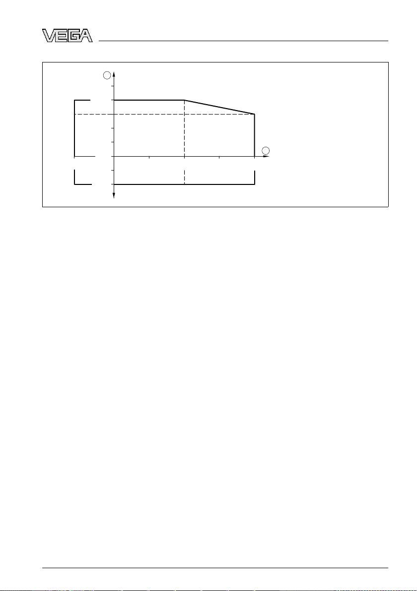
Fig. 24: Ambient
temperature - process temperature (version -110 … +400 °C/-166 … +752 °F)
1 Process temperature
2 Ambient temperature
32764-EN-080716
VEGAFLEX 66 • Profibus PA 51
Page 52

10 Suppl
ement
Electrome
Cable entry/plug
chanical data - version IP 66/IP 67 and IP 66/IP 68; 0.2 bar
4)
- Single chamber housing l 1 x cable gland M20 x 1.5 (cable:
ø 5 … 9 mm), 1 x
blind stopper M20 x 1.5
or:
l 1 x
closing cap M20 x 1.5; 1 x
blind
stopper M20 x 1.5
or:
l 1 x
closing cap ½ NPT, 1 x blind plug
½ NPT
or:
l 1 x plug (depending
on the version), 1 x
blind stopper M20 x 1.5
- Double chamber housing l 1 x cable entry M20 x 1.5 (cable:
ø 5 … 9 mm), 1 x
blind stopper M20 x 1.5;
1 x blind stopper M16 x 1.5 or optionally
available with 1 x plug M12 x 1 for
VEGADIS 61
or:
l 1 x
closing cap ½ NPT, 1 x
blind stopper
½ NPT, 1 x blind stopper M16 x 1.5 or
optionally 1 x plug M12 x 1 for VEGADIS
61
or:
l 1 x
plug (depending
on the version), 1 x
blind stopper M20 x 1.5; 1 x blind stopper
M16 x 1.5 or optionally available with 1 x
plug M12 x 1 for VEGADIS 61
Spring-loaded terminals for wire cross-
> 2.5 mm² (AWG 14)
section
Electromechanical data - version IP 66/IP 68, 1 bar
Cable entry
- Single chamber housing 1 x IP 68 cable gland M20 x 1.5; 1 x blind
stopper M20 x 1.5
- Double chamber housing 1 x IP 68 cable gland M20 x 1.5; 1 x blind
stopper M20 x 1.5; 1 x blind stopper M16 x 1.5
4)
Depending on the version M12 x 1, according to DIN 43650, Harting, Amphenol-Tuchel, 7/8" FF.
52 VEG
AFLEX 66 • Profibus PA
32764-EN-080716
Page 53

10 Sup
plement
Connectio
n cable
- Wire cross-section 0.5 mm² (AWG 20)
- Wire resistance < 0.036 Ω/m
- Tensile strength < 1200 N (270 lbf)
- Standard length 5 m (16.4 ft)
- Max. length 1000 m (3280 ft)
- Min. bending radius 25 mm (0.984 in) with 25 °C (77 °F)
- Diameter approx. 8 mm (0.315 in)
- Colour - standard PE Black
- Colour - standard PUR Blue
- Colour - Ex-version Blue
Indicating and adjustment module
Voltage supply and data transmission through the sensor
Indication LC display in Dot matrix
Adjustment elements 4 keys
Protection
- unassembled IP 20
- mounted into the sensor without
IP 40
cover
Materials
- Housing ABS
- Inspection window Polyester foil
Voltage supply
Supply voltage
- Non-Ex instrument 9 … 32 V DC
- EEx-ia instrument 9 … 24 V DC
Supply voltage with lighted indicating and adjustment module
- Non-Ex instrument 12 … 32 V DC
- EEx-ia instrument 12 … 24 V DC
Power supply by/max. number of sensors
- DP/PA segment coupler max. 32 (max. 10 with Ex)
- VEGALOG 571 EP card max. 15 (max. 10 with Ex)
32764-EN-080716
VEGAFLEX 66 • Profibus PA 53
Page 54

10 Suppl
Electri
ement
cal protective measures
Protection, depending on housing version
- Plastic housing IP 66/IP 67
- Aluminium housing, stainless steel
IP 66/IP 68 (0.2 bar)
housing - investment casting, stainless steel housing - electro-polished
- Aluminium and
stainless housing,
IP 66/IP 68 (1 bar)
investment casting (optionally available)
Overvoltage category III
Protection class II
5)
Approvals
6)
Approvals
- ATEX ia ATEX
II 1G, 1/2G, 2G
EEx ia IIC T6
- ATEX ia+d ATEX II 1/2G, 2G EExd ia IIC T6
- IEC ia IEC Ex ia IIC T6
- IEC ia+d IEC Ex d ia IIC T6
- FM FM CI.I, Div 2 (NI)+CI.II, III, Div 1 (DIP); FM
CI.I-III, Div 1 (IS); FM CI.I-III, Div 1 (IS)+Cl.I-III,
Div 1 Gr.C-G(XP)
- CSA CSA CI.I, Div 2 (NI)+CI.II, III, Div 1 (DIP); FM
CI.I-III, Div 1 (IS); FM CI.I-III, Div 1 (IS)+Cl.I-III,
Div 1 Gr.C-G(XP)
- Miscellaneous WHG
5)
A suitable cable is the prerequisite for maintaining the protection class.
6)
Deviating data in Ex applications: see separate safety instructions.
54 VEG
32764-EN-080716
AFLEX 66 • Profibus PA
Page 55

10 Sup
plement
10.2 Profibus P
A
Instrument master file
The instrument master file (GSD) contains the characteristic data of the Profibus PA
instrument. These data are, e.g. the permissible transmission rates as well as information
on diagnostics values and the format of the measured value outputted by the PA
instrument.
A bitmap file is also provided for the Profibus network planning tool. This file is installed
automatically when the GSD file is integrated. The bitmap file is used for symbolic
indication of the PA instrument in the configuration tool.
Ident number
Each Profibus instrument gets an unambiguous ident number (ID number) from the
Profibus user organisation (PNO). This ID number is also included in the name of the GSD
file. For VEGAFLEX 66 the ID number is 0 x 0771(hex) and the GSD file FX__0771.GSD.
Optionally to this manufacturer-specific GSD file, PNO provides also a general so-called
profile-specific GSD file. For VEGAFLEX 66 you have to use the general GSD file
PA139700.GSD. If the general GSD file is used, the sensor must be set to the profilespecific ident number via the DTM software. By default, the sensor operates with the
manufacturer-specific ID number.
Cyclical data traffic
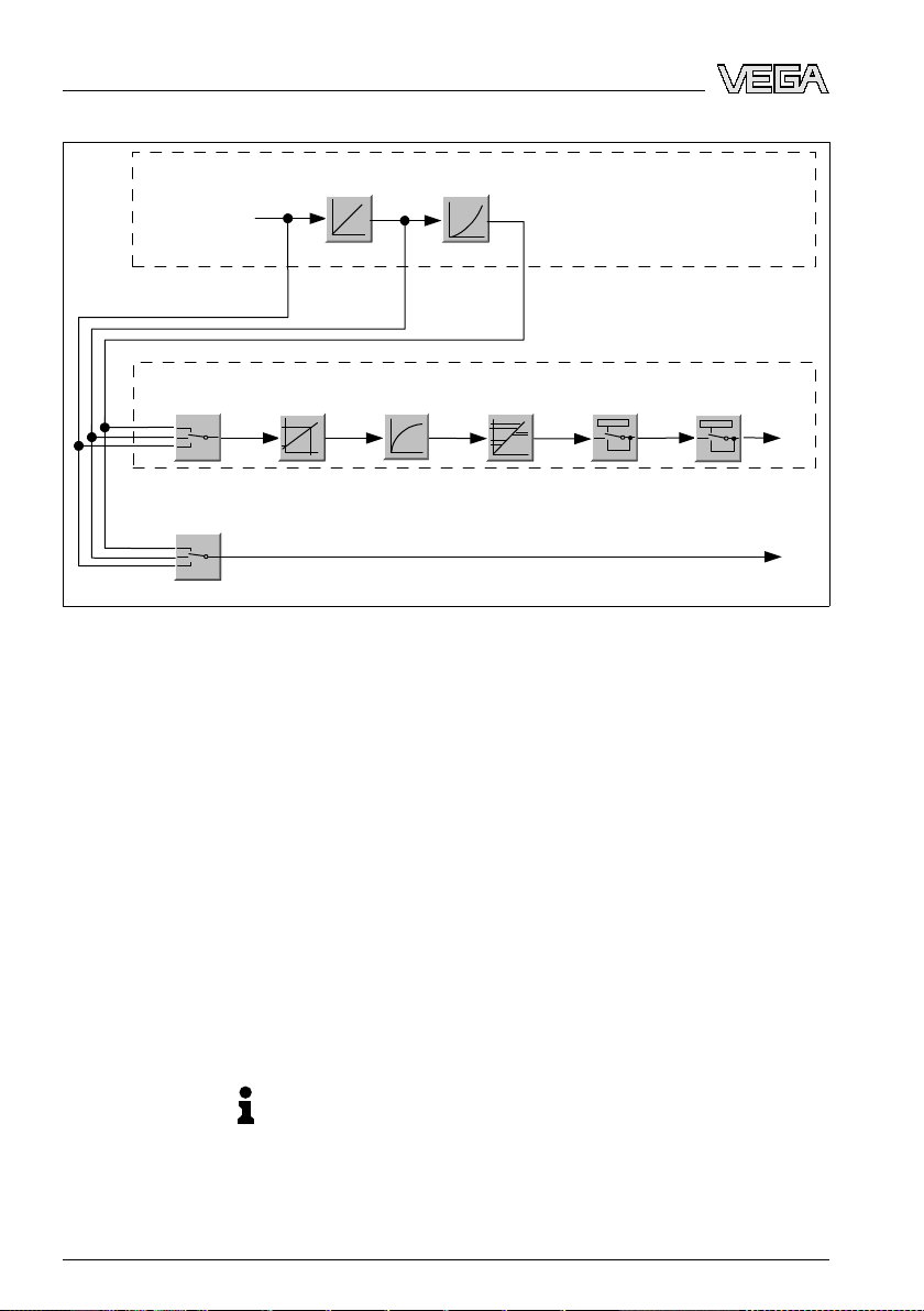
The master class 1 (e.g. PLC) cyclically reads out measured values from the sensor
during operation. The below block diagram below shows which data can be accessed by
the PLC.
32764-EN-080716
VEGAFLEX 66 • Profibus PA 55
Page 56
m(d) % Lin%
Min-Max
adjustment
Linearization
PROFIBUS PA-output
Primary
Value
Secondary
Value 2
Secondary
Value 1
Target
Mode
Failure
mode
AlarmsScaling
Source for
scaling
t
i
Integration
Sensor
characteristics
PA -Out
TB
FB
Select additional cyclic
value
10 Suppl
ement
Fig. 25: VEGAFLEX 66: Block
TB Transducer Block
FB Function Block
diagram with AI (PA-OUT) value and additional cyclical value
Module of the PA sensors
For the cyclic data traffic, VEGAFLEX 66 provides the following modules:
l AI (PA-OUT)
- PA-OUT value of
l Additional Cyclic Value
- Additional cyclical value (depending on the source)
l Free Place
- This module must be used if a value should not be used in the data telegram of the
cyclical
Max. three modules can be active. By means of the configuration software of the Profibus
master, you can determine the configuration of the cyclical data telegram with these
data traffic (e.g. replacement of the Additional Cyclic Value)
the FB1 after scaling
modules. The procedure depends on the respective configuration software.
Note:
The
modules are available in two versions:
l Short
Format" byte, e.g. Allen Bradley
rofibus master supporting only one "Identifier
for P
56 VEG
AFLEX 66 • Profibus PA
32764-EN-080716
Page 57
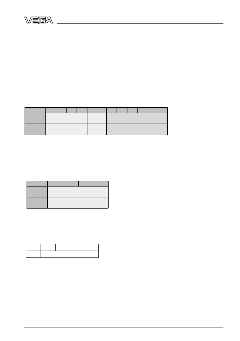
Byte-No.
1 2 3 4 5 6 7 8 9 10
Status
Status
Status
Status
(FB1)
IEEE-754-
Floating point value
PA -OUT
(FB1)
IEEE-754-
Floating point value
Additional Cyclic
Value
Format
Value
Byte-No.
1 2 3 4 5
Status
Status
(FB1)
IEEE-754-
Floating point value
PA -OUT
(FB1)
Format
Val ue
Byte4
Byte3
Byte2
Byte1
Byte0
Status Value (IEEE-754)
10 Sup
plement
l Long for P
rofibus master only supporting the "Identifier
Format" byte, e.g. Siemens S7-300/400
Examples of telegram configuration
In the following you will see how the modules can be combined and how the appendant
data telegram is structured.
Example 1 (standard setting) with distance value and additional cyclical value:
l AI (PA-OUT)
l Additional Cyclic Value
Exampl
l AI (PA-OUT)
l Free Place
e 2 with distance value without additional cyclical value:
format of the output signal
Data
Fig. 28: Data
format of the output signal
The status byte corresponds to profile 3.0 "Profibus PA Profile for Process Control
Devices" coded. The status "Measured value OK" is coded as 80 (hex) (Bit7 = 1, Bit6 … 0
= 0).
The measured value is transferred as a 32 bit floating point number in the IEEE-754
format.
32764-EN-080716
VEGAFLEX 66 • Profibus PA 57
Page 58
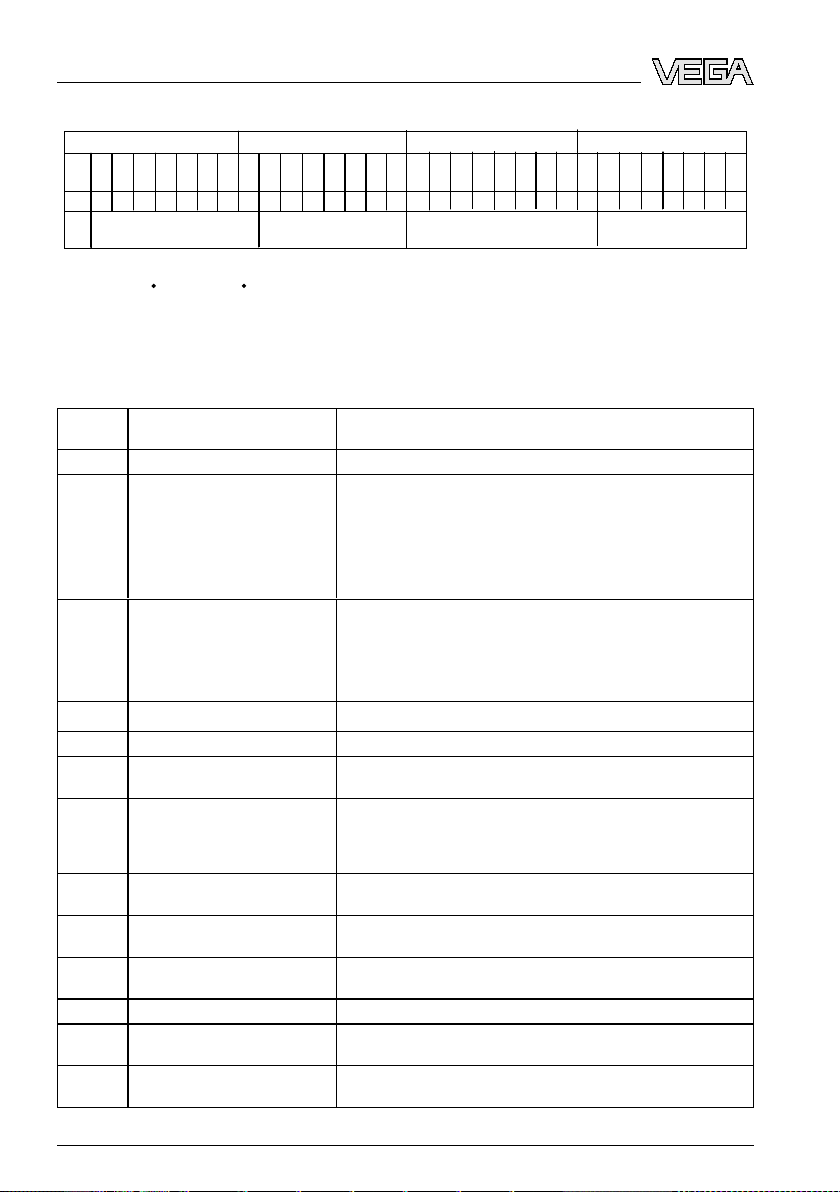
Byte n
Byte n+1
Bit
7
VZ
Exponent
Bit
6
2
Bit
5
2
Bit
4
2
Bit
3
2
Bit
2
2
Bit
1
2
Bit
0
2
Bit
7
2
Bit
6
2
Bit
5
2
Bit
4
2
Bit
3
2
Bit
2
2
Bit
1
2
Bit
0
2
Sign
Bit
Significant
7
6
543
2 10-1
-2-3-4-5-6 -7
Byte n+2
Byte n+3
Bit
7
2
Significant
Bit
6
2
Bit
5
2
Bit
4
2
Bit
3
2
Bit
2
2
Bit
1
2
Bit
0
2
Bit
7
2
Bit
6
2
Bit
5
2
Bit
4
2
Bit
3
2
Bit
2
2
Bit
1
2
Bit
0
2
Significant
-9
-10
-11
-12
-13
-14 -15
-16
-17
-18
-19
-20
-21
-22
-23
-8
Value = (-1)
VZ
2
(Exponent - 127)
(1 + Significant)
10 Suppl
ement
Fig. 29: Data
format of the measured value
Coding of the status byte associated with the PA output value
Status
code
0x00 bad - non-specific Flash-Update active
0x04 bad - configuration error
Description according to Pro-
fibus standard
Possible cause
l Adjustment error
l Configuration error
small)
l Unit irregularity
l Error in the linearization table
0x0C bad - sensor
0x10 bad - sensor
0x1f bad - out of service constant "Out of Service" mode switched on
0x44 uncertain - last unstable value Failsafe replacement value (Failsafe-Mode = "Last value" and
0x48 uncertain substitute set
0x4c uncertain - initial value Failsafe replacement value (Failsafe-Mode = "Last valid value" and
0x51 uncertain - sensor; conversion
0x52 uncertain - sensor; conversion
0x80 good (non-cascade) - OK OK
0x84 good (non-cascade) - active
0x89 good (non-cascade) - active ad-
58 VEG
not accurate - low limited
not accurate - high limited
block alarm
visory alarm - low limited
failure
failure
l Hardware error
l Converter error
l Leakage pulse error
l Trigger error
l Measured value generation error
already valid measured value since switching on)
l Switch on simulation
l Failsafe replacement value (Failsafe-Mode =
"Fsafe
value")
no valid measured value since switching on)
Sensor value < lower limit
Sensor value > upper limit
Static revision (FB, TB) changed (10 sec. active, after the parameter
of the static category was written)
Lo-Alarm
with PV-Scale (PV-Span too
AFLEX 66 • Profibus PA
32764-EN-080716
Page 59

10 Sup
plement
Status
code
0x8a good (non-cascade) - active ad-
0x8d good (non-cascade) - active crit-
0x8e good (non-cascade) - active crit-
Description
fibus standard
visory alarm - high limited
ical alarm - low limited
ical alarm - high limited
according to Pro-
Possible cause
Hi-Alarm
Lo-Lo-Alarm
Hi-Hi-Alarm
32764-EN-080716
VEGAFLEX 66 • Profibus PA 59
Page 60

~ 69 mm
(2 23/32")
ø 77 mm
(3 1/32")
112 mm (4
13
/
32
")
M20x1,5/
½ NPT
~ 69 mm
(2 23/32")
ø 77 mm
(3
1
/32")
117 mm (4
39
/
64
")
M20x1,5/
½ NPT
~ 87 mm (3 27/64")
M16x1,5
ø 84 mm
(3 5/16")
120 mm (4
23
/
32
")
M20x1,5/
½ NPT
~ 116 mm (4 9/16")
ø 84 mm (3 5/16")
116 mm (4
9
/
16
")
M20x1,5M20x1,5/
½ NPT
~ 59 mm
(2 21/64")
ø 80 mm
(3
5
/32")
112 mm (4
13
/
32
")
M20x1,5/
½ NPT
1 3 4
5
2
10 Suppl
ement
10.3 Dim
ensions
Housing in protection IP 66/IP 67 and IP 66/IP 68; 0.2 bar
Fig. 30: Housing
adjustment module the housing is 9 mm/0.35 in higher)
1 Plastic housing
2 Stainless steel housing, electropolished
3 Stainless steel housing - precision casting
4 Aluminium double chamber housing
5 Aluminium housing
versions in protection IP 66/IP 67 and IP 66/IP 68, 0.2 bar (with integrated indicating and
60 VEG
32764-EN-080716
AFLEX 66 • Profibus PA
Page 61

117mm (4
39
/
64
")
120mm (4
23
/
32
")
~ 103mm
(4 1/16")
~ 105mm (4 9/64")
ø 77mm
(3 1/32")
116mm (4
9
/
16
")
~ 150mm (5 29/32")
ø 84mm (3 5/16")
ø 84mm
(3 5/16")
~ 93 mm
(3 21/32")
ø 80 mm
(3
5
/32")
112 mm (4
13
/
32
")
M20x1,5/
½ NPT
M20x1,5
M20x1,5/
½ NPT
M16x1,5
1
2 3
M20x1,5M20x1,5
4
10 Sup
plement
Housing
Fig. 31: Housing
in protection IP 66/IP 68, 1 bar
versions in protection IP 66/IP 68, 1 bar (with integrated indicating and adjustment module the
housing is 9 mm/0.35 in higher)
1 Stainless steel housing - precision casting
2 Aluminium double chamber housing
3 Stainless steel housing, electropolished
4 Aluminium housing
32764-EN-080716
VEGAFLEX 66 • Profibus PA 61
Page 62

L
150 mm (5.91")
53 mm
(2.09")
ø 6 mm
(0.24")
12 mm
(0.47")
ø 54 mm
(2.13")
ø 20 mm
(0.79")
ø 4 mm
(0.16")
ø 30 mm
(1.18")
271 mm (10.67")
22 mm
(0.87")
SW 50
(
1.97")
G1 / 1”NPT,
G1½ / 1½”NPT
10 Suppl
ement
VEGAFLEX 66 - cable, rod
version (-110 … +400 °C/-166 … +752 °F)
Fig. 32: VEGAFLEX 66 - cable, rod
version with thread (-110 … +400 °C/-166 … +752 °F)
L Sensor length, see chapter "Technical data"
62 VEG
32764-EN-080716
AFLEX 66 • Profibus PA
Page 63

L
271 mm (10
5
/
8
")
18 mm (
45
/
64
")
29 mm (1
9
/
64
")
ø 21,1 mm
(53/64")
SW 50
(1
31
/32")
G1 / 1”NPT,
G1½ / 1½”NPT
10 Sup
plement
VEGAFLEX 66 - coax
version (-110 … +400 °C/-166 … +752 °F)
Fig. 33: VEGAFLEX 66 - coax
version with thread (-110 … +400 °C/-166 … +752 °F)
L Sensor length, see chapter "Technical data"
32764-EN-080716
VEGAFLEX 66 • Profibus PA 63
Page 64

10 Suppl
ement
10.4 In
dustrial property rights
10.5 Trademark
VEGA product lines are global protected by industrial property
rights. Further information see http://www.vega.com.
Only in U.S.A.: Further information see patent label at the
sensor housing.
VEGA Produktfamilien sind weltweit geschützt durch
gewerbliche Schutzrechte.
Nähere Informationen unter http://www.vega.com.
Les lignes de produits VEGA sont globalement protégées par
des droits de propriété intellectuelle. Pour plus d'informations,
on pourra se référer au site http://www.vega.com.
VEGA lineas de productos están protegidas por los derechos
en el campo de la propiedad industrial. Para mayor
información revise la pagina web http://www.vega.com.
Линии продукции фирмы ВЕГА защищаются по всему
миру правами на интеллектуальную собственность.
Дальнейшую информацию смотрите на сайте http://www.
vega.com.
VEGA系列产品在全球享有知识产权保护。
进一步信息请参见网站<http://www.vega.com>。
All brands used as well as trade and company names are
property of their lawful proprietor/originator.
64 VEG
32764-EN-080716
AFLEX 66 • Profibus PA
Page 65

10 Sup
plement
32764-EN-080716
VEGAFLEX 66 • Profibus PA 65
Page 66

10 Suppl
ement
66 VEG
32764-EN-080716
AFLEX 66 • Profibus PA
Page 67

10 Sup
plement
32764-EN-080716
VEGAFLEX 66 • Profibus PA 67
Page 68

VEGA Grieshaber KG
ISO 9001
Am Hohenstein 113
77761 Schiltach
Germany
Phone +49 7836 50-0
Fax +49 7836 50-201
E-mail: info@de.vega.com
www.vega.com
Printing date:
statements concerning scope of delivery, application,
All
practical use and operating conditions of the sensors and
processing systems correspond to the information avail-
able at the time of printing.
© VEGA Grieshaber KG, Schiltach/Germany 2008
Subject to change without prior notice 32764-EN-080716
 Loading...