

Page 1
Operating Instructions
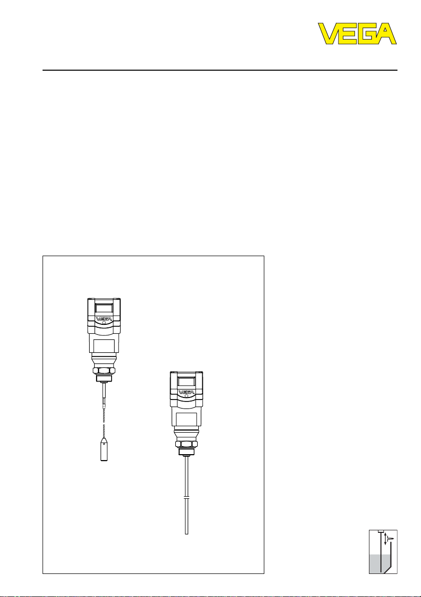
VEGAFLEX 54K
Level and Pressure
Page 2

Safety information / Note Ex area
Safety information
Please read this manual carefully, and also take
note of country-specific installation standards
(e.g. the VDE regulations in Germany) as well
as all prevailing safety regulations and accident prevention rules.
For safety and warranty reasons, any internal
work on the instruments, apart from that involved in normal installation and electrical connection, must be carried out only by qualified
VEGA personnel.
2 VEGAFLEX 54K
Note Ex area
Please note the attached safety instructions
containing important information on installation
and operation in Ex areas.
These safety instructions are part of the operating instructions and come with the Ex approved instruments.
Page 3

Contents
Contents
Safety information ........................................................................ 2
Note Ex area ................................................................................ 2
1 Product description
1.1 Function ................................................................................. 4
1.2 Application features ............................................................. 4
1.3 Types and versions ............................................................. 5
1.4 Type code ............................................................................. 7
1.5 Technical data ....................................................................... 8
1.6 Dimensions ......................................................................... 11
2 Mounting
2.1 Installation instructions ...................................................... 14
3 Electrical connection
3.1 Connection and connection cable .................................... 16
3.2 Connection of the sensor .................................................. 18
3.3 Connection of the indicating instrument VEGADIS 50 .... 20
4Setup
4.1 Adjustment media .............................................................. 21
4.2 Adjustment with the adjustment module MINICOM ........ 21
4.3 Adjustment with the PC ...................................................... 28
4.4 Adjustment with HART® handheld ..................................... 31
5 Diagnosis
5.1 Simulation ............................................................................ 32
5.2 Failure rectification ............................................................. 32
VEGAFLEX 54K 3
Page 4

1 Product description
Product description
1.1 Function
High frequency microwave impulses are
guided along a steel rope or a rod.
The microwave impulses are reflected when
they reach the product surface. The impulse
running time is processed by the integrated
electronics and outputted as level.
The sensors detect levels in all types of liquids. Density, conductivity and dielectric
value of the product do not influence the
measurement. Continuously changing properties of the medium also do not influence the
measured value.
In many applications, VEGAFLEX microwave
sensors are the solution to difficult technical
problems. Even in products with varying or
fluctuating dielectric constant, the level is
reliably detected. In high, narrow vessels,
where non-contact measurement technologies often deliver less than optimal results,
VEGAFLEX carries out problem-free measurements. VEGAFLEX 54 is optionally
equipped with a 4 mm diameter cable up to a
length of 20 m, or an 8 mm diameter rod up
to a length of 4 m.
• Adjustment without filling or emptying the
vessel.
• 4 … 20 mA two-wire sensors, power supply and measuring signal via one two-wire
cable (loop powered).
• Up to 15 sensors can be connected via
one two-wire cable.
• Measuring range up to 20 m, very small
minimum measuring distance.
• Unaffected by application conditions such
as:
- varying products
• Unaffected by the vessel material, e.g.
metal, concrete, plastic etc.
• As an option, the display with adjustment
functions can be mounted separate from
the sensor.
• Low wiring costs through the use of twowire technology.
1.2 Application features
Applications
• Level measurement of liquids.
• Measurement also in vacuum.
• All slightly conductive substances and all
substances with a dielectric value ε
can be measured.
• Measuring range 0 ... 20 m.
Two-wire technology
• Power supply, signal transmission and
output signal on one two-wire cable.
• 4 … 20 mA output signal or digital output
signal.
Rugged
• Highly resistant materials: PCTFE, 1.4435,
Hastelloy C22.
Precise and reliable
• Resolution 1 mm.
• Unaffected by noise, steam, gas compositions and inert gas stratification.
• Unaffected by varying density.
• Measurements under pressure up to
40 bar and with product temperatures up
to 150°C.
Communicative
• Integrated measured value display.
• As an option, display can be mounted
separate from the sensor.
• Adjustment from the PLC level.
Approvals
• ATEX II 1 G or II 1/2 G or II 2 G EEx ia
II C T6
• ATEX II 1/2 G or II 2 G EEx d ia II C T6
> 1.7
r
4 VEGAFLEX 54K
Page 5
Product description
Adjustment with PC
The setup and adjustment of VEGAFLEX
sensors is generally done on the PC with the
adjustment program VVO (VEGA Visual Operating) under Windows®.
The program leads quickly through adjustment and parameter setting by means of
pictures, graphics and process
visualisations.
The PC can be connected at any individual
location in the system or directly to the signal
cable. This is done by connecting the twowire PC interface converter VEGACONNECT 2
or 3 to the sensor or to the signal cable.
The adjustment and parameter data can be
saved with the adjustment software on the
PC and can be protected by passwords. On
request, the adjustments can be quickly
transferred to other sensors.
Adjustment with adjustment module
MINICOM
With the small (3.2 cm x 6.7 cm) 6-key adjustment module MINICOM, the adjustment
can be carried out in clear text dialogue.
The adjustment module can be plugged into
VEGAFLEX or the external indicating instrument VEGADIS 50.
Thus, VEGAFLEX can also be adjusted ffrom
the external indicating instrument VEGADIS
50.
Tank 1
m (d)
12.345
ESC
+
-
OK
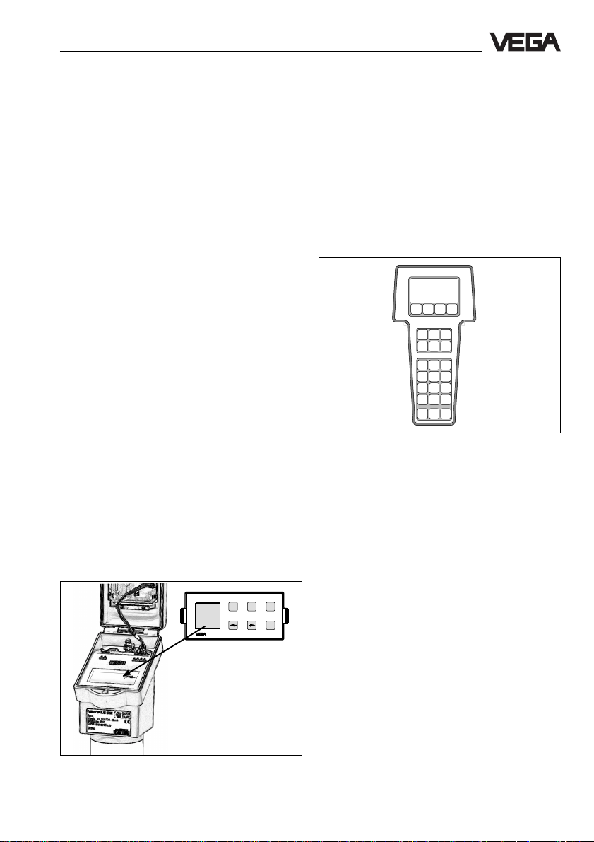
Adjustment with HART® handheld
Series 50 sensors with 4 … 20 mA output
signal can also be adjusted with the HART
handheld or via a PC with HART® software
(e.g. Smart version). A special DDD (Data
Device Description) is not necessary. The
sensors can be adjusted with the HART
standard menus of the handheld.
HART Communicator
HART® handheld
®
®
1.3 Types and versions
VEGAFLEX series 50 K
In general, all VEGAFLEX series 50 sensors
can be adjusted with the pluggable adjustment module MINICOM or with any standard
HART® handheld. With the software VEGA
Visual Operating (VVO), it is also possible to
adjust the sensor with a PC.
4 … 20 mA sensors
Two-wire sensors for connection to a power
supply unit or a PLC.
Detachable adjustment module MINICOM
VEGAFLEX 54K 5
Page 6
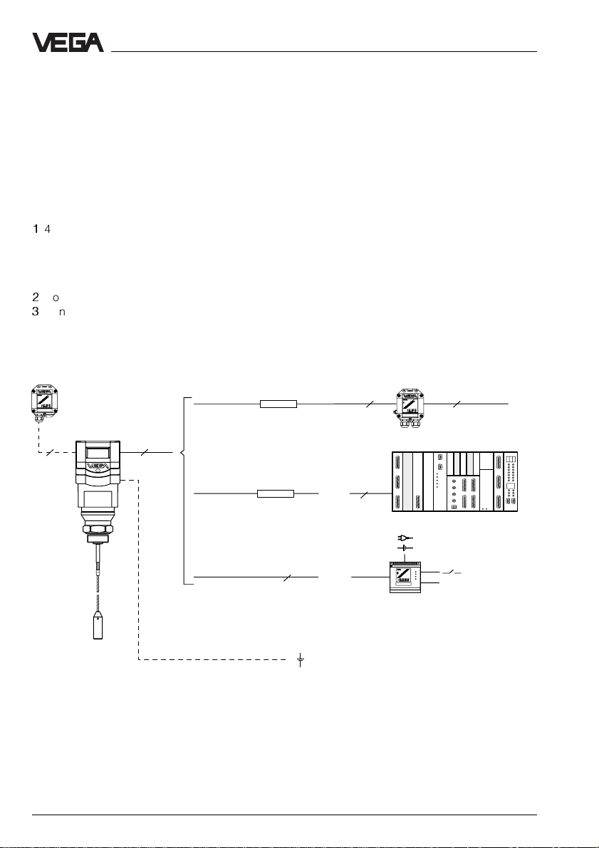
Configuration
A measuring system with a VEGAFLEX can
be realised in different ways (see following
illustration).
The external indicating instrument VEGADIS
50 can be mounted up to 25 m away from the
sensor.
Two-wire technology
1
4 ... 20 mA sensor, power supply and
measuring signal via one two-wire cable
(loop-powered), indicating instrument
VEGADIS 11 only possible with four-wire
technology.
2
Connection to a PLC (active).
3
Connection to indicating instrument
VEGADIS 371 with up to four relay outputs.
VEGADIS 50
1
VEGAFLEX
4
2
Product description
1)
2 2
4 … 20 mA
VEGADIS 11
1)
4 … 20 mA
passive
2
4 … 20 mA
passive
+
-
2
PLC
+
-
VEGADIS 371 Ex
Relay (4 x)
0/4 … 20 mA
1)
only with HART
2
3
®
6 VEGAFLEX 54K
Page 7
Product description
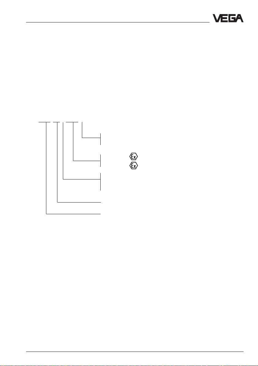
1.4 Type code
The second figure of the type name, e.g.
VEGAFLEX 5[4]… distinguishes the instruments according to the type and version of
the sensor component.
The letter, e.g. VEGAFLEX 54[K] characterises the output signal:
K stands for an analogue 4 … 20 mA output
signal (compact instrument)
P stands for a digital signal transmission for
connection to Profibus PA
VEGAFLEX 54 K .CX D
D - Two-wire loop-powered / 4 … 20 mA output, HART
®
G - Profibus PA
CX - ATEX II 1 G or II 1/2 G or II 2 G EEx ia II C T6
DX - ATEX II 1/2 G or II 2 G EEx d ia II C T6
P - Profibus PA
K - Analogue 0 … 20 mA output signal (two-wire technology)
Instrument series with 4 mm cable / 8 mm rod
Measuring principle (FLEX for guided microwave)
VEGAFLEX 54K 7
Page 8
1.5 Technical data
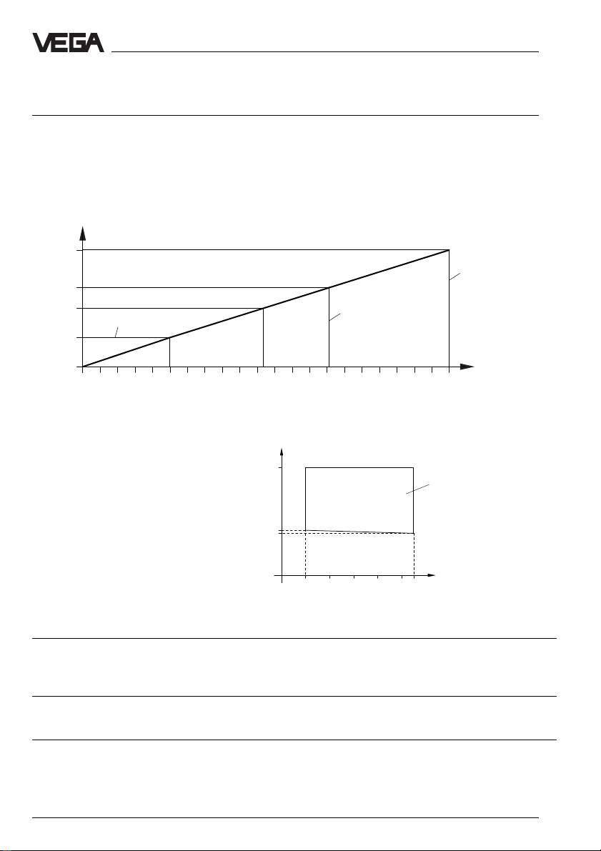
Power supply
Supply voltage
- two-wire sensor 24 V DC (15 … 36 V DC)
Current consumption
- two-wire sensor max. 22.5 mA
Power consumption
- two-wire sensor max. 810 mW
Ω
1000
680
500
250
HART® load
Voltage limit
Ex sensor
Product description
Voltage limit
Non-Ex sensor
0
20 22 24 26 28 30 32 34 3615 16 18
V
Supply voltage
The min. supply voltage depends on the sensor current.
V
36
15
14
04 22
Range of the required
terminal voltage on the
sensor
Sensor current
mA
Measuring range
VEGAFLEX 54 rod 0.15 ... 4 m (with DK value > 4: 0.1 … 4 m)
cable 0.15 … 20 m (with DK value < 4: 0.3 … 20 m)
Output signal
4 … 20 mA current signal, load max. 500 Ω
Adjustment
- PC and adjustment software VEGA Visual Operating
- adjustment module MINICOM
- HART® handheld
8 VEGAFLEX 54K
Page 9

Product description
Accuracy (under reference conditions acc. to IEC 770 - relating to the max. meas. range)
Linearity error < 0.1 %
Temperature drift 0.015 %/10 K
Resolution of the 4 … 20 mA signal 0.025 % of range (DA converter)
Resolution 1 mm
Characteristics
Min. span between
full and empty adjustment
- analogue output signal 10 mm
Ambient conditions
Vessel pressure -1 … 40 bar
Ambient temperature on the housing -40°C … +60°C
Process temperature -40°C … +150°C
Storage and transport temperature -40°C … +80°C
Protection IP 66/IP 67 (meets both protection standards)
Protection class
- two-wire sensor II
- four-wire sensor I
Overvoltage category III
Max. tensile load cable ø 4 mm: 1 KN
rod ø 8 mm: 1 KN
Min. dielectric constant ε
> 1.7
r
Process fittings
VEGAFLEX 54 G1 A, 1" NPT, G 11/2 A, 11/2" NPT
of 1.4435 (stst; 316L) or
Hastelloy C22 plated
Ex technical data
Ex-Zone 0 acc. to ATEX II 1 G or II 1/2 G or II 2 G EEx ia II C T6, ATEX II 1/2 G or II 2 G
EEx d ia II C T6 and ATEX II 1/2 G
The permissible operating data of the VEGAFLEX sensors for Ex areas are listed in the
certificate.
Materials
Housing PBT (Valox) or
Aluminium (powder-coated)
Rod 1.4435 (stst; 316L) or Hastelloy
Cable 1.4401 (stst; 316L)
VEGAFLEX 54K 9
Page 10

Product description
gravity weight 1.4435
Connection cables
Two-wire sensor
- power supply and signal via one two-wire cable.
The cable resistance depends on the supply voltage (see diagram).
Conductor cross-section generally 2.5 mm
Ground connection max. 4 mm
2
2
Cable entry 2 x M20 x 1.5 (cable diameter 5 … 9 mm)
2 x 1/2" NPT with ExD housing
CE conformity
VEGAFLEX sensors meet the protective regulations of EMC (89/336/EWG) and NSR
(73/23/EWG). Conformity has been judged acc. to the following standards:
EMC Emission EN 50 081 - 1: 1992
Susceptibility EN 50 082 - 2: 1995
NSR EN 61 010 - 1: 1993
Display
Display scalable, analogue and digital display of
measured values (option).
An external measured value display, powered by the sensor, can be mounted at a distance
of up to 25 m from the sensor.
Signal output
Signal output
- two-wire technology 4 … 20 mA (see diagram)
Resolution of the 20 mA signal 0.025 % of range
Load 0 … 500 Ω
Two-wire technology:
The analogue 4 … 20 mA output signal (measuring signal) is transmitted together with the
power supply via one two-wire cable.
10 VEGAFLEX 54K
Page 11
Product description
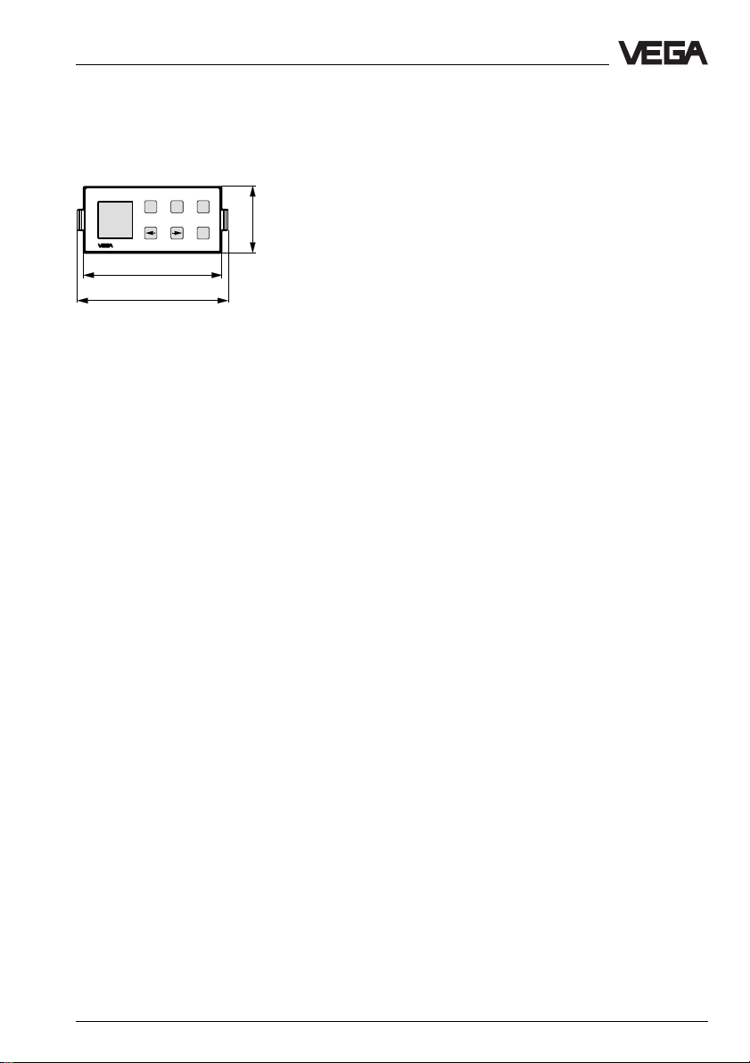
1.6 Dimensions
Adjustment module MINICOM
Tank 1
m (d)
12.345
67,5
74
ESC
+
-
OK
Adjustment module for insertion
32,5
into series 50
sensors or into
the external indicating instrument
VEGADIS 50
VEGAFLEX 54K 11
Page 12

Plastic housing A luminium housing
201
165
Product description
322
182
Thread Thread
G 1A / 1" NPT G 11/2A / 11/2" NPT
SW41
G1A
1NPT
ø 8 ø 8ø 20
10˚
91
ø 4
M20x1,5
80
70
215
101
0
7
3
5
0
2
55
22
L
185
SW60
G1 1/2A
1 1/2NPT
25
M20x1,5
ø 4
ø 20
116
55
26
80
L
70
Flange
53
24
88
L
70
ø 8
ø 4
ø 20
ø 200
12 VEGAFLEX 54K
Page 13

Product description
Aluminium housing with ExD terminal compartment
ø 8
215
185
370
205
Flange Thread Thread
(Hastelloy C22) G 1A / 1" NPT G 11/2A / 11/2" NPT
24
4
L 53
ø 138
ø 200
SW41
G1A
1NPT
25
½" NPT
ø 8
116
(Hastelloy C22) (Hastelloy C22)
SW60
55
22
G1 1/2A
1 1/2NPT
L
ø 8
55
33, 5
L
VEGAFLEX 54K 13
Page 14

2 Mounting
Mounting
2.1 Installation instructions
Lateral load
Make sure that the cable is not subjected to
strong lateral forces. Mount VEGAFLEX at a
location where no interference caused by,
e.g., stirrers, filling inlets etc. can occur.
Lateral load
Pressure
In case of gauge or low pressure in the vessel, the mounting boss must be sealed on the
thread. Make sure that the seal ring is resistant to the medium.
Cable entries
When mounting outdoors, on cooled vessels
or in humid areas where cleaning is done,
e.g. with steam or high pressure, the seal of
the electrical cable entry is very important.
Use electrical cable with a round cross-section and tighten the cable entry firmly. The
cable entry is suitable for cable diameters of
5 mm to 9 mm.
Moisture from outside
To avoid moisture ingress, the connection
cable leading to the housing should be
looped downward (directly in front of the
cable entry), so that rain and condensation
water can drain off. This mainly applies to
outdoor mounting, in areas where moisture is
expected (e.g. by cleaning processes) or to
cooled or heated vessels.
Moisture
14 VEGAFLEX 54K
Page 15

Mounting
Measuring range
The electrode (rod / cable) cannot be used
over its entire length.
Keep especially in mind that the cable length
cannot be utilised down to the very tip. A measurement in the area of the gravity weight is not
possible.
Rod 0.15 ... 4 m (with DK value > 4: 0.1 … 4 m)
Cable 0.15 … 20 m (with DK value < 4: 0.3 … 20 m)
x
100%
L
Measuring range
L
0%
Sockets
Avoid long sockets. Mount the sensor flush
and use short sockets with small diameters.
Note under 4.3 Adjustment with PC / Empty
vessel profile.
x
100%
0%
VEGAFLEX 54K 15
Page 16

3 Electrical connection
Electrical connection
3.1 Connection and connection cable
Safety information
As a rule, do all work in the complete absence of line voltage. Always switch off the
power supply before you carry out connecting work on the sensors. Protect yourself
and the instrument, especially when you use
sensors which do not work with low voltage.
Qualified personnel
Instruments which are not operated with a
protective low voltage must only be connected by qualified personnel.
Connection
For connection, a standard two-wire cable
with max. 2.5 mm2 can be used. Quite often
the "Electromagnetic pollution" from electronic
actuators, energy lines and transmitting
stations is so considerable that the two-wire
cable should be shielded.
We recommend the use of shielded cable.
Shielding is also a good preventative measure against future sources of interference.
Ground the shielding only on one sensor end
(fig. 3.1 a). It is advantageous to ground the
shielding on both ends. However, you must
make sure that no earth equalisation currents
flow through the cable shielding (fig. 3.1 b).
Earth equalisation currents (when grounding
at both ends) can be prevented by connecting the cable shielding on one end (e.g. in
the switching cabinet) via a capacitor (e.g.
0.1 µF; 250 V AC) to the earth potential. Use
a very low-resistance earth connection (foundation, plate or mains earth). In Ex applications, the shielding should be grounded only
at one end. Potential transfer can be caused
when grounding at both ends.
Ex protection
If an instrument is used in hazardous areas,
the necessary regulations as well as the Ex
certificate of VEGAFLEX for systems in Ex
areas should be noted.
Connection cable
Make sure that the connection cables are
specified for the expected operating temperatures in your systems.
The cable must have an outer diameter of
5 … 9 mm (1/5 ... 1/3 inch). Otherwise, the seal
effect of the cable entry will not be ensured.
Cables for intrinsically safe circuits must be
marked blue and must not be used for other
circuits. Note the special wiring regulations
for Profibus PA sensors (P), see "1.5 Technical data connection cables".
Earth conductor terminal
On VEGAFLEX sensors, the earth conductor
terminal is galvanically connected to the metal
thread.
16 VEGAFLEX 54K
Page 17

Electrical connection
Grounding at one end (next to the sensor)
Processing
Fig. 3.1 a
Grounding at both ends (on the signal conditioning instrument via the potential separating capacitor)
≥ 0.1 µF
250 V AC
Processing
Fig. 3.1 b
VEGAFLEX 54K 17
Page 18
Electrical connection
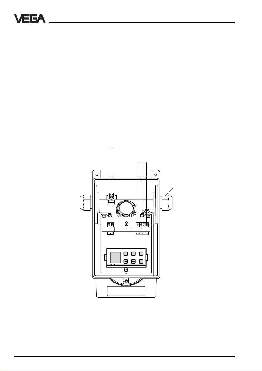
3.2 Connection of the sensor
• Loosen the closing screws on the upper
side of the sensor.
• Open the sensor cover.
• Remove the sleeve nut from the cable
fitting and slide it a short distance up the
connection cable.
• Remove the rubber seal from the cable
fitting and slide it also a short distance up
the connection cable.
• Remove the outer insulation of the connec-
tion cable over a length of approx. 10 cm.
4 … 20 mA
passive
+
• Insert the cable through the cable fitting
into the sensor.
• Connect the cables. Push the white tabs of
the spring-loaded terminals with a small
screwdriver and insert the copper core of
the connection cable into the terminal opening. Check the hold of the individual wires
in the terminals by pulling lightly on them.
• Screw the sleeve nut back onto the cable
fitting and screw it down tightly.
1)
To the indicating instrument in the
-
sensor cover or to the external indicating instrument VEGADIS 50
M20 x 1.5
(diameter of the
connection cable
5 … 9 mm)
+ 1
4-20mA
2 -
Communication
5678
-+
Display
ESC
OK
2.23272
Two-wire technology (analogue)
(loop powered)
1)
4 … 20 mA passive means that the sensor
consumes a level-dependent current of
4 … 20 mA (consumer).
18 VEGAFLEX 54K
Page 19

Electrical connection
Exd version (loop-powered with pressure-tight encapsulated terminal compartment)
EEx d terminal compartment
(opening in Ex area not allowed)
4 … 20 mA passive
1)
-+
Locking of the cover
Exd terminal box
Supply: 20...36V DC/4...20mA HART
Shield
-
+
2
1
2
1
1)
4 … 20 mA passive means that the sensor
consumes a level-dependent current of
4 … 20 mA (consumer).
1
/2" NPT EEx d
(diameter of the
connection cable
3.5 … 8.7 mm)
Adjustment module and indication terminal compartment
(opening in Ex area allowed)
1
/2" NPT EEx d
(diameter of the
connection cable to
the Exd terminal box
3.5 … 8.7 mm)
Exd safe channel
through to the Exd
terminal box
1
+-2
4-20mA
Communication
-+
ESC
Display
OK
8765
2.23272
VEGAFLEX 54K 19
Page 20

3.3 Connection of the indicating instrument VEGADIS 50
Loosen the 4 screws of the housing cover on
VEGADIS 50. The connection procedure can
be facilitated during connecting work by
fastening the cover to one side of the housing
with the afore-mentioned screws.
Adjustment
module
OUTPUT
(to the sensor)
SENSOR
DISPLAY
(in the cover of the
indicating instrument)
DISPLAY1234 5678
Tank 1
m (d)
12.345
ESC
+
-
OK
Electrical connection
VEGADIS 50
Screws
4 … 20 mA
passive
+
-
to VEGADIS 50
(use shielded cable. See fig. 3.1 a or
fig. 3.1 b)
M20x1.5
Communication
-+
5678
Display
ESC
OK
2.23272
+ 1
4-20mA
2 -
Two-wire sensor
(loop powered)
20 VEGAFLEX 54K
Page 21

Setup
4 Setup
4.1 Adjustment media
Series 50 sensors can be adjusted with the
- PC (adjustment program VVO)
- detachable adjustment module MINICOM
- HART® handheld.
It is only possible to use one adjustment
device at a time.
Adjustment module MINICOM
With the adjustment module MINICOM, you
can adjust directly in the sensor or in the
external indicating instrument VEGADIS 50.
With a dialogue text display and 6 keys, the
module offers the same adjustment functionality as the adjustment software VVO.
Adjustment program VVO
With the adjustment program VVO (VEGA
Visual Operating System) on the PC, the
sensors can be adjusted in a very convenient, user-friendly manner. The PC communicates with the sensor via the interface
converter VEGACONNECT 2 or 3. A digital
adjustment signal is superimposed on the
signal and supply cables. The PC can be
connected at any location along the cable or
directly to the sensor.
HART® handheld
VEGAFLEX 50 K sensors, like other HART
protocol-compatible instruments, can be
adjusted with the HART® handheld. A manufacturer-specific DDD (Data Device Description) is not required. The sensors
communicate with the HART® standard
menus, through which all sensor functions
are accessible. Functions that are rarely
used, such as, for example, the scaling of the
A/D converter for the signal output or the
adjustment with medium, are not possible or
are blocked with the HART® handheld. These
functions must be carried out with the PC or
the adjustment module MINICOM.
®
4.2 Adjustment with the adjustment module MINICOM
Just as with the PC, you can adjust the sensor with the small, detachable adjustment
module MINICOM. The adjustment module is
plugged into the sensor or into the external
indicating instrument (optional).
All the adjustment options provided by a PC
with the adjustment program VVO are also
available with the adjustment module
MINICOM. You can carry out all adjustment
steps with the 6 keys of the adjustment module. A small display shows you, apart from
the measured value, a short message on the
menu item or an entered numerical value.
ESC
+
-
Tank 1
m (d)
12.345
OK
2
4 ... 20 mA
ESC
+
-
Tank 1
m (d)
12.345
OK
4
VEGAFLEX 54K 21
Page 22

Setup
Adjustment elements
The adjustment module MINICOM is menuorientated. The clear text indications on the
display lead through the menu. The functions
of the keys are described below.
2
1
Tank 1
-
m (d)
12.345
5
"OK" key (4)
With the "OK" key you can confirm the settings.
When the symbol ▼ or is shown in the digital
indication, you can switch to the lower menu
level with the "OK" key.
The symbol indicates there is no branching
point below the menu item, but only a further
▼
▼
menu item of the respective function.
"ESC" key (3)
With the "ESC" key (Escape) you can interrupt an adjustment or a current function or
switch to the next higher menu level.
To reach e.g. the uppermost menu level,
push the "ESC" key several times.
"+" and "–" key (2)
With the "+" and "–" keys you can modify the
values of the parameters or choose from a
number of options.
After an initial push, the value to be adjusted
flashes. Each additional push changes the
value.
3
ESC
+
OK
4
▼
▼
Arrow keys (5)
With the keys "–>" and "<–", you can move
within the menu level from one menu item to
the next.
Digital indication (1)
During operation, the digital display shows
the actual measured value.
When adjusting the instrument, the clear text
display shows the respective function.
▼ Branching point, from where you can
move to the next lower menu.
▼
This symbol informs you of a subsequent
▼
safety enquiry.
Adjustment steps
On the following pages, you will see the menu
schematic of the adjustment module
MINICOM.
Set up the sensor in the following sequence.
The numbers correspond to the sequence of
the setup. You will find the numbers with the
respective menu items in the menu schematic
on the following pages.
1. Adjustment
2. Conditioning
3. Outputs
4. Operating range
5. Measuring conditions
6. Indication of the useful signal and noise
level
22 VEGAFLEX 54K
Page 23

Setup
1. Adjustment
Under the menu item "
the sensor of the measuring range it should
operate in.
The instruments are already adjusted to the
respective probe length. You only have to
carry out a max. adjustment and enter the
max. level.
Max.
Min.
You can carry out the adjustment with or
without medium. Generally, you will carry out
the adjustment without medium, because you
can adjust without having to fill the vessel.
Adjustment without medium
• Enter the distance of your sensor to the
medium at 0 % (example: 5.850 m) with the
"+" and "–" key.
If you do not know the distance, you have
to do a sounding.
• Enter the distance from the sensor to the
medium at 100 % filling.
Adjustment
100 % (distance to the product
0.300 m) corresponds to
1200 liters, e.g. 20 mA
0 % (distance to the product
5.850 m) corresponds to 456
liters, e.g. 4 mA)
", you inform
Meas. range
Key Display indication
Sensor
m(d)
4.700
Para-
OK
OK
OK
OK
1)
In case of two values which can be modified, you
meter
adjustment
Adjustment
w.o.
medium
Adjustment
in
(min. adjustment)
m(d)
0.0 %
at
m (d)
XX.XXX
1)
can move with the "+" key to the second value
(confirm with the "OK" key).
Adjustment with medium
Fill the vessel e.g. to 10 %, enter in the menu
"
Min-adjustment
" with the "+" and "–" keys
10 % and confirm with the "OK" key. Then fill
the vessel e.g. to 80 % or 100 %, enter in the
menu "
Max-adjustment
" with the "+" and "–"
keys 80 % or 100 % and confirm with the
"OK" key.
with
medium
Max.
Min.
adjust
adjust
at %
at %
XXX.X
XXX.X
VEGAFLEX 54K 23
Page 24

Setup
2. Conditioning
Under the menu item "
choose the distance at 0 % and at 100 %
filling. Then you enter the physical quantity
and the unit as well as the decimal point.
• Enter in the menu window "
spond
" the value of the 0 % filling. This will
be e.g. "80" for 80 liters.
• Confirm with "OK".
• With the arrow key you switch to the 100 %
menu. Enter here the value of your parameter corresponding to a 100 % filling. E.g.
"1200" for 1200 liters.
• Confirm with "OK".
• If necessary, choose a decimal point. Note
that max. 4 digits can be shown.
• In the menu "
parameter (mass, volume, distance…),
• In the menu "
unit (kg, l, ft3, gal, m3 …).
• With the "ESC" key, you go back to the next
higher menu level. With the arrow key, you
choose the next menu item.
• In the menu
between three standard linearisation
curves.
A linear correlation between percentage
value of the product distance and the percentage value of the filling volume has
been preset.
You can choose between linear, spherical
and cylindrical tank. Entering a user-programmable curve is only possible with the
PC and the adjustment program VVO.
• In the menu item
set a delay period for the signal output.
Conditioning
0 % corre-
prop. to
", you choose the
Unit
", you choose the physical
"Lin. curve",
you can choose
"Integration time",
" you
you can
3. Outputs
Under the menu "
e.g. if the current output should be inverted,
or which parameter should be indicated on
the sensor display.
Outputs
", you determine
4. Operating range
Without special adjustment, the operating
range corresponds to the measuring range.
The measuring range was already adjusted
with the min./max. adjustment. It is generally
better to choose a slightly wider span for
operating range (approx. 5 %) than for the
measuring range (span).
Example:
Min./Max. adjustment: 0.300 … 5.850 m; set
operating range to approx. 0.250 … actual
cable length.
5. Meas. conditions
With these functions, you can enter the ambient conditions in the vessel (see menu schematic).
24 VEGAFLEX 54K
Page 25

Setup
6. Useful level and noise level
In the menu
tion on the signal quality of the product echo.
The higher the "
the measurement.
Ampl.: Means amplitude of the product echo
S-N: Means Signal-Noise (useful signal
The higher the S-N value (useful signal
level minus noise level), the higher the reliability:
> 30 dB Measurement good
10 … 30 dB Measurement satisfactory
< 10 dB Measurement bad
"Info"
you get important informa-
S-N
" value, the more reliable
in dB (useful signal level)
level minus noise level)
VEGAFLEX 54K 25
Page 26

Menu schematic of the adjustment module MINICOM
Setup
Sensor
m(d)
4.700
Parameter
adjustment
Sensor
optimize
Sensor
Tag
Sensor
Meas.
environment
Operating
range
Begin
m (d)
0.50
FLEX54
After switching on, the sensor type and the
K
software version are displayed for a few seconds.
0.50
4.
Cable
length
m (d)
6.00
Meas.
conditions
Low
DK
value
No
5.
Empty
vessel
profile
Create
new
Meas.
dist.
m (d)
X.XX
Create
new
Now !
OK ?
Learning!
Update
Meas.
dist.
m (d)
X.XX
Update
Now !
OK ?
Learning!
Delete
Delete
Now !
OK ?
Deleting !
Adjustment
w.o.
medium
Adjustment
in
m(d)
1.
with
medium
Min.
adjust
at %
XXX.X
0.0 %
at
m (d)
XX.XXX
Max.
adjust
at %
XXX.X
100.0%
at
m (d)
XX.XXX
Note:
Set up the sensor in the sequence of the
numbers.
Signal
conditioning
Scaling
0 %
corres
ponds
XXXX
2.
Lin.
curve
Linear
100 %
corres
ponds
XXXX
Integr
ation
time
Decimal
point
888.8
0 s
prop.
Unit
to
Mass
kg
26 VEGAFLEX 54K
Page 27

Setup
Add’l
functions
With these keys you move in
the menu field to the left, the
right, top and bottom.
ESC
OK
Outputs
mA
output
act.
dist.
m (d)
4.700
Ampl.:
XX dB
S-N:
XX
dB
Info
Reset
to default
Reset
Now!
OK ?
Reset
runs!
Language
English
Meas.
unit
m (d)
6.
Sensor
Tag
Sensor
Sensor
type
FLEX54
K
Serial
number
1094
0213
Softw.
vers.
1.00
Softw.
date
15.09.
1997
dist.
m (d)
4.700
S-N:
XX dB
XX
dB
Ampl.:
act.
3.
Simulation
Sensor
displ.
Simulation
Now!
OK ?
Simulation
XXX.X
%
act.
dist.
m
X,XX
Meas.
unit
m (d)
Bolt print figures are sensor or
measured value information and
cannot be modified in this position.
The menu items in white letters
stand for figures which can be
modified with the "+" or "–" key
and saved with the "OK" key.
mA
output
4-20mA
prop.
to
Distance
Failure
mode
22mA
VEGAFLEX 54K 27
Page 28

Setup
4.3 Adjustment with the PC
Connection
The PC with the adjustment program VVO
(VEGA Visual Operating from version 2.80)
can be connected to the
- sensor or
- signal cable.
PC on the sensor
To connect the PC to the sensor, the interface
converter VEGACONNECT 2 or 3 is required.
Plug it into the provided CONNECT sockets
in the sensor.
PC on the signal cable
Connect the two-wire cable of
VEGACONNECT 2 / 3 to the supply cable
(two-wire sensor) of the sensor. If the resistance of the systems (PLC, current source
etc.) connected to the supply cable is less
than 250 Ω, a resistor of 250 … 350 Ω must
be connected to the supply cable during
adjustment. The digital signals modulated
onto the signal cable would otherwise be
considerably damped (short-circuited)
through insufficient resistance, and communication with the PC would not be ensured.
+
250 ... 350 Ω
-
You have connected the PC with the adjustment software VVO to your measuring system.
• Now switch on the power supply of the
connected sensor.
In the first 10 … 15 seconds the sensor starts
to draw a current of approx. 22 mA (selftest)
and then takes on a level-proportional or distance-proportional current of 4 … 20 mA.
• Start the adjustment software VVO on your
PC.
• In the entrance window, you choose with
the arrow keys or the mouse the item
ning"
and click to
You should choose
"OK"
.
"Planning"
"Plan-
only if you
are authorised to modify instrument parameters. Otherwise choose
"Maintenance"
In the window
.
"User identification",
"Operator"
or
you are
asked for the name and the password.
• For setup (
name:
"VEGA"
Planning
"VEGA"
), you enter under
and under password also:
. It does not matter if the words are
entered in small or capital letters.
VVO determines then automatically the type
of the connected sensor and indicates a
moment later with which sensor a connection
exists.
If you get no communication with the sensor,
check the following:
- The supply voltage must be at least 15 V at
4 mA or 14 V at 22 mA.
- In case VEGACONNECT 2 / 3 is directly
connected to the sensor cable, the load
resistance must be 250 … 350 Ohms.
- You have to use a VEGACONNECT 2 or 3.
Older versions of VEGACONNECT are not
compatible.
VEGACONNECT 2/3
You will find further information on adjustment
with the PC and the adjustment software VVO
in the operating instructions manual of the
adjustment software VEGA Visual Operating
(VVO).
28 VEGAFLEX 54K
Page 29

Setup
Special function
If a VEGAFLEX sensor is found, several
special functions of VEGAFLEX can be chosen with the adjustment software VVO.
Under the menu item "Instrument data/Parameter adjustment", you can select sensor
optimisation.
Here you find all special functions of
VEGAFLEX:
- Meas. environment
- Echo curve
Meas. environment
Meas. conditions
Select in this menu which medium you want to
measure in.
If you want to measure a product with a DK
value below 4, you can increase the sensitivity of the sensor here.
Operating range
With this command, you can limit the operating range of the sensor.
Carry out the adjustment before modifying
the operating range, as a later adjustment will
overwrite the values of the operating range.
Echo curve
The echo curve shows all reflections of the
guided microwave signal.
This means that not only the level signal is
shown, but also interference signals, e.g.
caused by vessel installations. The sensor
generally interprets the highest amplitude as
the level echo.
A black arrow is shown above the highest
amplitude peak. When clicking to "Display
info", a small window will be displayed, listing
the detailed information on the selected echo.
The right part of the graphics shows the
operating range, the left part the adjustment.
If e.g. you do not want to fill your vessel completely, you can limit the operating range.
VEGAFLEX 54K 29
Zoom/Unzoom
After activation of one of these two functions,
you can either zoom or unzoom the curve
with the left mouse key.
When activating "Zoom", you can choose the
requested part of the picture by pressing the
left mouse key and drawing a frame.
Page 30
The following curves can be displayed:
Raw value curve (red)
The red curve represents the absolute signal, detected by the receiver of VEGAFLEX.
Beside the useful echo, this curve also contains interference signals. The highest amplitude is interpreted as the level echo. Check
by sounding if the value of the useful echo
corresponds to the real distance to the medium. If the two values do not correspond,
you have to filter out the dominant false echoes with the function "Empty vessel profile".
Setup
Start
If you click "Start", the echo curve is updated
continuously. With "Stop" you can terminate the
update.
Vessel profile (blue)
In normal condition, this curve represents the
beginning and end of the vessel.
To filter out false echoes, you can modify the
blue curve of the vessel profile with the function "Empty vessel profile".
Reference line (green)
All amplitudes of the red curve which are
below the green reference line will be suppressed (ringing, noise, false echoes, etc.).
All amplitudes above this line are possible
echoes that will be evaluated by the software.
Logarithmic raw value curve (black)
This curve represents the difference between
raw value curve (red) and reference line
(green). The scale on the right (dB) applies
to this curve.
Documentation
If you click the button "Documentation", the
immediate echo curve will be saved.
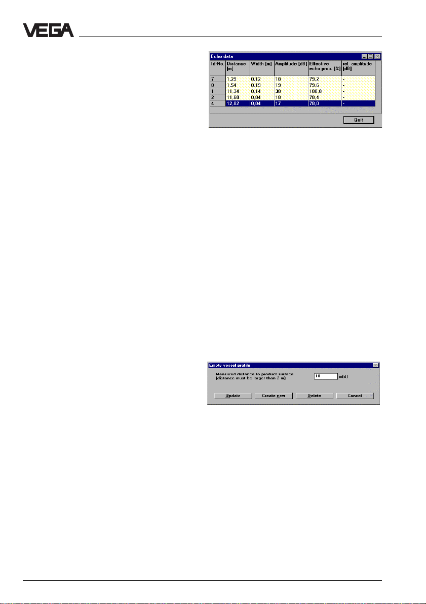
Echo data
If you click the button "Echo data", a window
is displayed in which all echoes detected by
the sensor are listed with dB information and
a probability evaluation.
Empty vessel profile
With the functions in this window, you can filter
out false echoes. The blue empty vessel profile
curve in the echo curve window represents the
actual empty vessel profile.
Determine the level by sounding. It is possible
to filter out the echo if the sensor has interpreted a false echo as the probable level echo
instead of the sounded level. Choose the function "Create new". Enter the sounded distance
to the medium. All false echoes within the range
of the adjusted distance are gated out automatically. Please note that the blue curve of the
empty vessel profile also changes.
With "Update" you can extend the empty vessel
profile, in case new false echoes appear when
the level falls.
If you want to delete the existing empty vessel
profile, click "Delete".
If VEGAFLEX is mounted on a socket or a
mounting boss, the measurement may be
inaccurate at close range. If the socket or
mounting boss exceeds the following lengths,
you should carry out an empty vessel profile
storage:
Thread 1", 11/2" - length > 50 mm
Flange DN 50 - length > 50 mm
Flange DN 80 - length > 80 mm
Flange ≥ DN 100 - length > 100 mm
30 VEGAFLEX 54K
Page 31

Setup
4.4 Adjustment with HART® handheld
The VEGAFLEX sensors can be set up with
any HART® handheld. A special DDD (Data
Device Description) is not necessary. Just
connect the HART® handheld to the signal
cable after having connected the sensor to
power supply.
Note
If the resistance of the signal current circuit is
less than 200 Ω, a resistor of 250 … 350 Ω
must be connected to the signal/connection
cable during adjustment. Simply loop the
resistor into the sensor connection cable
(see figure).
+
250 ... 350 Ω
The most important adjustment steps
You will find the complete adjustment procedure via HART® protocol in the operating
instructions of the HART® handheld.
To enter parameters, first press "
Generic: SENSOR
PV LRV
5.850 m
0.300 m
HELP DEL ABORT EN TER
The entered value will be saved in the
handheld, but not in the sensor itself.
Press "
SEND
" to transmit the entered value to
the sensor.
ENTER
".
-
SPS
PLC
Generic: SENSOR
1 LRV 5.850 m
2 PV URV 0.300 m
HELP SEND HOME
Press "OK" to acknowledge the following
warning. Follow the instructions on the display.
Press again "OK", and the adjustment that
was just carried out is displayed.
Generic: SENSOR
1 LRV 5.850 m
2 PV URV 0.300 m
HELP HOME
VEGAFLEX 54K 31
Page 32

Diagnosis
5 Diagnosis
5.1 Simulation
To simulate a certain filling, you can call up the function "Simulation" on the adjustment module
MINICOM, in the software program VVO or in the HART® handheld. This function simulates a
certain current value. Please keep in mind that connected devices, such as e.g. a PLC, react
according to their settings and will probably activate alarms or system functions.
5.2 Failure rectification
Error Corrective measure
E 013 Sensor does not find a - Message is displayed during the warm-up
E 017 Adjustment span too small Carry out the adjustment again. Make sure that
E 036 Software update incorrect Return the instrument for repair.
E 040 Hardware failure/ Check all connection cables.
level echo phase.
- If the message remains, the DK value of the
medium might be too low.
Check the useful level and noise level.
See "4.2 Adjustment with adjustment module
MINICOM; 6. Useful level and noise level".
If the message still remains, carry out a new
adjustment.
the difference between min. and max. adjustment is at least 10 mm.
Electronics defective Contact our service department.
32 VEGAFLEX 54K
Page 33

Notes
VEGAFLEX 54K 33
Page 34

Notes
34 VEGAFLEX 54K
Page 35

Notes
VEGAFLEX 54K 35
Page 36

VEGA Grieshaber KG
Am Hohenstein 113
D-77761 Schiltach
Phone (07836) 50-0
Fax (07836) 50-201
E-Mail info@de.vega.com
www.vega.com
ISO 9001
All statements concerning scope of delivery, application, practical
use and operating conditions of the sensors and processing systems correspond to the latest information at the time of printing.
Technical data to subject to alterations
2.26 362 / November 2001
 Loading...