

Page 1
Operating Instruction
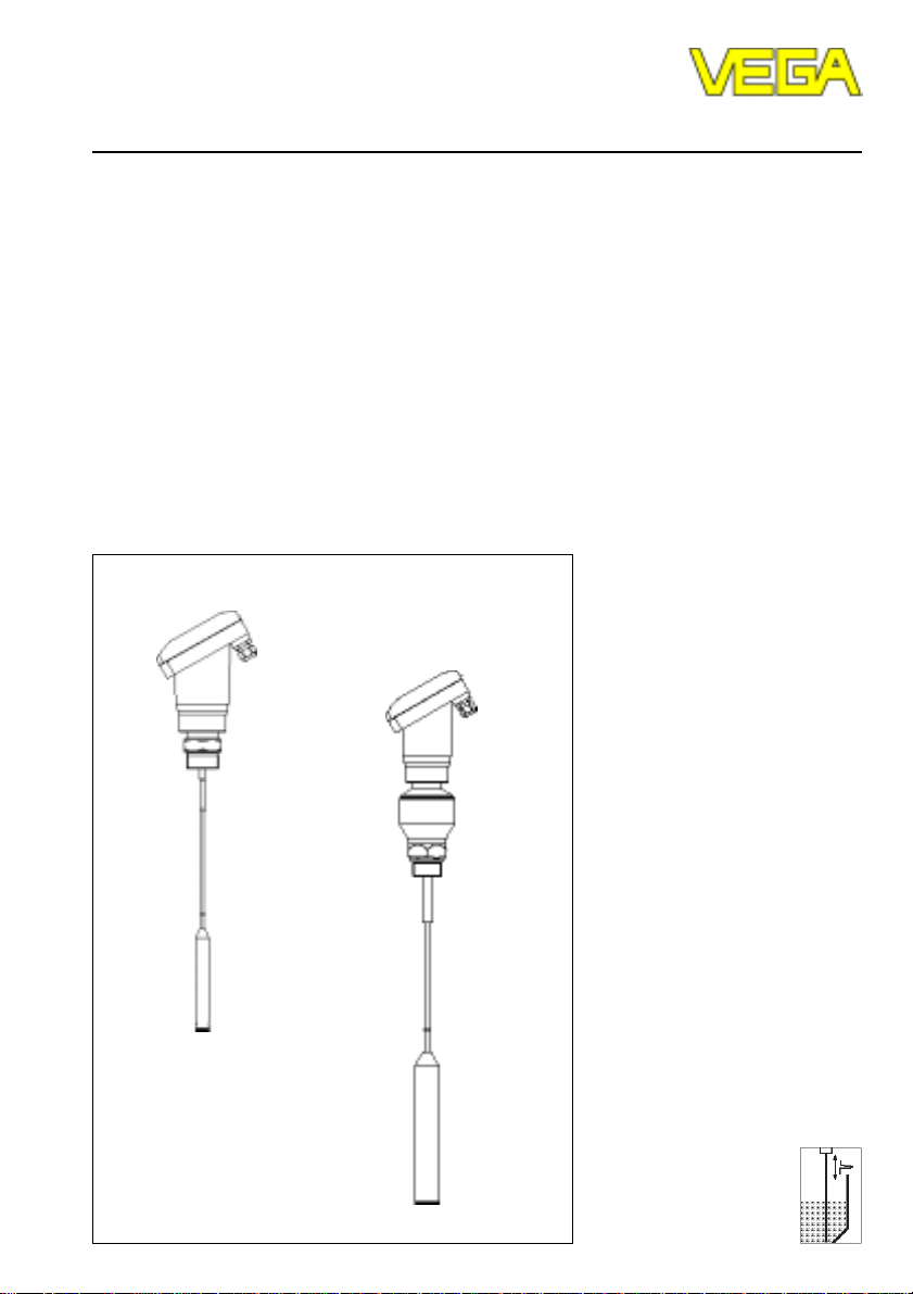
VEGAFLEX 51V and 52V
Level and Pressure
Page 2

Safety information / Note Ex-area
Safety information
The described module must only be installed
and operated as described in this operating
instruction. Please note that other action can
cause damage for which VEGA does not take
responsibility.
2 VEGAFLEX 51V and 52V
Note Ex-area
Please note the attached approval documents
(yellow binder) and especially the included
safety data sheet.
Page 3

Contents
Contents
Safety information ........................................................................ 2
Note Ex-area ............................................................................... 2
1 Product description
1.1 Function ................................................................................ 4
1.2 Application features ............................................................. 5
1.3 Types and versions............................................................. 7
1.4 Type code ............................................................................ 8
1.5 Technical data ...................................................................... 9
1.6 Approvals .......................................................................... 12
1.7 Dimensions ........................................................................ 12
2 Mounting
2.1 Installation instructions ...................................................... 14
3 Electrical connection
3.1 Connection and connection cable .................................... 18
3.2 Connection of the sensor .................................................. 20
3.3 Connection of the indicating instrument VEGADIS 50 .... 21
4 Set-up
4.1 Adjustment structure ......................................................... 22
4.2 Adjustment with adjustment module MINICOM ............... 23
4.3 Adjustment with PC ........................................................... 28
4.4 Adjustment with signal conditioning instrument .............. 31
5 Diagnosis
5.1 Simulation ........................................................................... 32
5.2 Error removal ..................................................................... 32
VEGAFLEX 51V and 52V 3
Page 4

1 Product description
1.1 Function
High frequency microwave impulses are
guided along a steel rope. When reaching
the product surface, the microwave impulses
are reflected. The running time of the impulses is processed by the integral electronics and provided as level.
The sensors measure levels of all kind of
solids. Density, conductivity and dielectric
constant of the medium do not influence the
measurement. Also varying solid characteristics do not influence the measured value.
Lime, cement, cereals, plastic granules, flour,
gravel - in solids VEGAFLEX microwave
sensors are the ideal solution for arduous
applications. The level is also reliably detected in products with varying humidity or
fluctuating dielectric constant. High, narrow
vessels in which non-contact measuring
principles often do not deliver optimum measuring results, VEGAFLEX can be used without problems.
VEGAFLEX 51 and 52 mainly differ in the
thickness of the measuring cable.
VEGAFLEX 51 has a cable with 4 mm diameter and is available up to a length of 10 m.
The cable of VEGAFLEX 52 has a diameter of
8 mm and can have a length of up to 20 m.
With the thicker cable it is also suitable for
solids with higher extraction forces.
Product description / Function
• Measuring range up to 20␣ m with small
min. distance
• Up to 15 sensors can be connected via
one two-wire cable
• Two-wire sensor, supply and digital
measuring signal via one two-wire cable
• Independent on application conditions
such as:
- dust and noise generation
- humidity changes
- varying products
- build-up
• Adjustment without vessel filling or emptying
• Individual wiring, with 15 sensors on one
two-wire line (digital output signal)
• Unaffected by vessel material, e.g. metal,
concrete, plastic etc.
4 VEGAFLEX 51V and 52V
Page 5
Product description / Application features
1.2 Application features
Application features
• Level measurement in solids
• Measurement also in vacuum
• All slightly conductive and all substances
with a dielectric constant εr > 1,7 can be
measured
• Measuring ranges
VEGAFLEX 51 0 … 10 m
VEGAFLEX 52 0 ... 20 m
Two-wire technology
• Supply, signal transmission and output
signal on one two-wire cable
• digital output signal
• low wiring costs due to the use of bus
systems or two-wire technology
Rugged
• High resistance materials: PA, 1.4401
Exact and reliable
• Resolution 1 mm
• Unaffected by noise, vapours, dusts, gas
compositions and layering
• Unaffected by varying density
• Measurements under pressure up to
16 bar and medium temperatures up to
120°C
Communicative
• Integral measured value indication
• Indication either separated from the sensor
• Adjustment from the DCS-level
• Connection to all bus systems:
Interbus S, Modbus, Siemens 3964R,
Profibus DP, Profibus FMS, ASCII
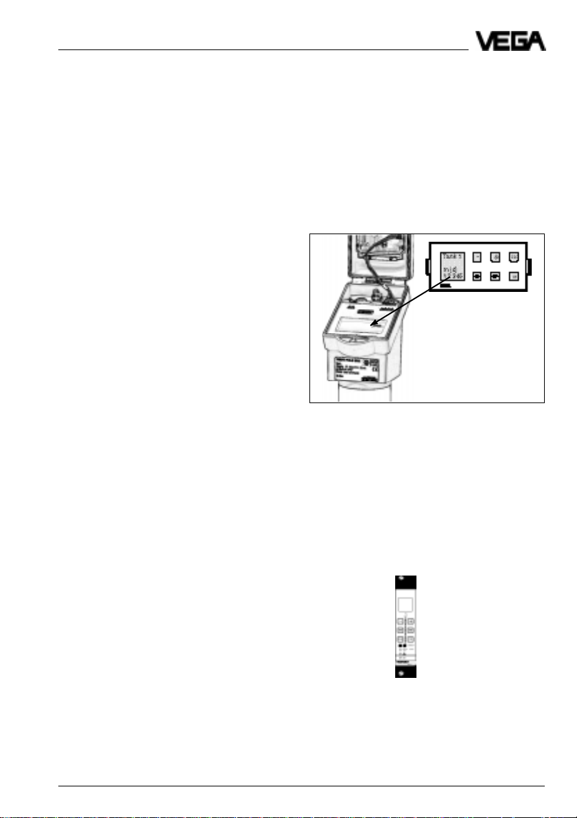
Adjustment with adjustment module
MINICOM
With the 6-key-adjustment module MINICOM
(3,2␣ cm␣ x␣ 6,7␣ cm) you can carry out the adjustment in clear text dialogue.
The adjustment module can be plugged into
VEGAFLEX or into the external indicating
instrument VEGADIS 50.
VEGAFLEX can therefore also be adjusted
from the external indicating instrument
VEGADIS 50.
Pluggable adjustment module MINICOM
Adjustment with VEGA signal conditioning instruments
VEGAFLEX-series 50V sensors can be also
operated with a VEGAMET signal conditioning instrument.
The display leads you in clear text. With the
6-key adjustment field the parameter adjustment can be carried out.
Approvals
Dust-Ex - Zone 10
VEGAFLEX 51V and 52V 5
Page 6
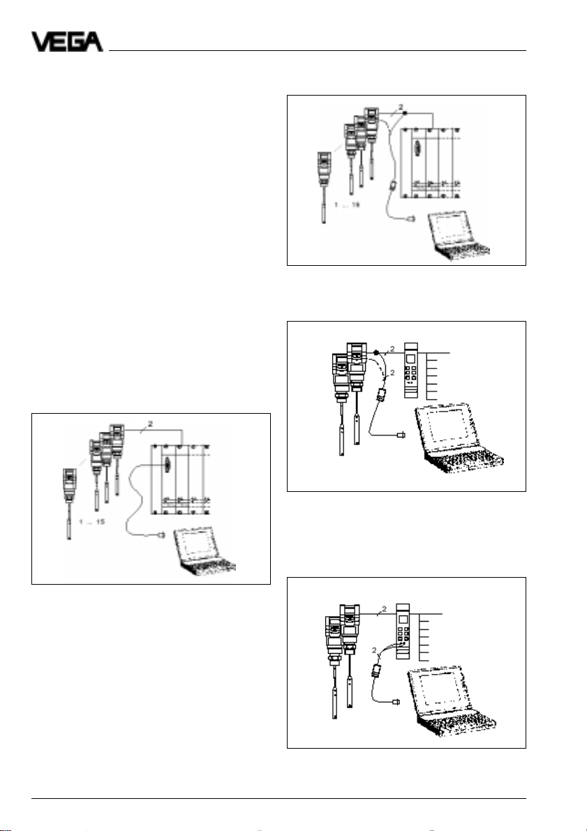
Adjustment with PC
The set-up and adjustment of the
VEGAFLEX-sensors can be made via PC
with the adjustment program VVO (VEGA
Visual Operating) under Windows®.
The software leads you quickly through the
adjustment and parameter adjustment by
means of pictures, graphics and process
visualisations.
The PC can be connected to any individual
position of the system or the signal line. It is
therefore connected with the two-wire PCinterface converter VEGACONNECT 2 to the
sensor or to the signal line.
The adjustment and parameter adjustment
data can be saved with the adjustment software on the PC. If necessary the adjustments
can also be transferred to other sensors.
On the following figures you see the different
connection possibilities.
Product description / Application features
Adjustment with the PC on the digital signal
and supply line to the processing system or
on the sensor
Adjustment with the PC on the digital signal
and supply line between sensor and
VEGAMET signal conditioning instrument
Adjustment with the PC and the standard
cable RS 232 on the processing system
Adjustment with the PC on the signal conditioning instrument
6 VEGAFLEX 51V and 52V
Page 7
Product description / Types and versions
1.3 T ypes and versions
VEGAFLEX series 50 V
Generally all VEGAFLEX series 50 V sensors
can be adjusted with the pluggable adjustment module MINICOM or with a VEGAMET
signal conditioning instrument.
The sensor can be adjusted with the software
VEGA Visual Operating (VVO) also via PC.
VEGADIS 50
1
Configuration
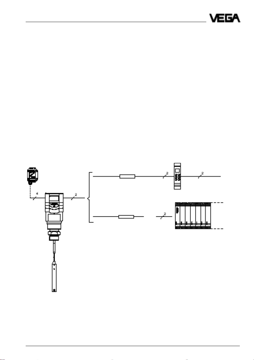
A measuring system with a VEGAFLEX is
possible in different ways.
See the following figures.
The external indicating instrument VEGADIS
50 can be mounted up to 25 m separated
from the sensor.
Two-wire technology
1 Connection to a VEGAMET 514V, 515V,
614V signal conditioning instrument
2 Connection to a VEGALOG 571
4 … 20 mA
VEGAFLEX
e.g. VEGAMET 514V
2
4 … 20 mA
passive
VEGALOG
VEGAFLEX 51V and 52V 7
Page 8
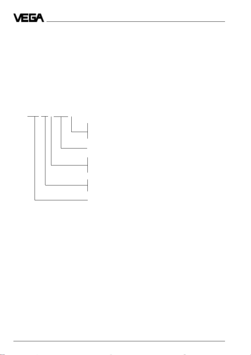
1.4 Type code
The second figure of the type designation,
e.g. VEGAFLEX 5[1]… distinguishes the
instruments according to the stability of the
cable.
The figure e.g. VEGAFLEX 51[V] characterizes the output signal:
K stands for an analogue 4␣ …␣ 20␣ mA output
signal (compact instrument)
V stands for a digital output signal (VBUS).
VEGAFLEX XX X EXS.X X
B - 20…72 V DC, 20...250 V AC / 4...20 mA-output, HART
D - Two-wire loop-powered / 4...20 mA-output, HART
E - Supply via signal conditioning instrument / V-BUS-output
Dust-Ex approved
V - Digital output signal (two-wire technology)
K - Analogue 0 … 20 mA output signal (two-wire or
four-wire technology)
Type 51: Instrument series with 4 mm-cable
Type 52: Instrument series with 8 mm-cable
Product description / Type code
®
®
Meas. principle (FLEX for guided microwave)
8 VEGAFLEX 51V and 52V
Page 9
Product description / Technical data
1.5 T echnical data
Power supply
Supply voltage from signal conditioning instrument VEGAMET
Current consumption max. 22,5 mA
Power consumption max. 80 mW, 0,45 VA
Measuring range
VEGAFLEX 51 0,3 … 10 m
VEGAFLEX 52 0,3 ... 20 m
Output signal
Digital measuring signal (VBUS)
Adjustment
- signal conditioning instruments VEGAMET 514V, 515V, 614V
- PC and adjustment software VEGA Visual Operating
- adjustment module MINICOM
Accuracy (under reference conditions acc. to IEC 770 - relating to the max. meas. range)
Linearity error < 0,1 %
Temperature drift 0,015 %/10 K
Resolution 1 mm
or from the processing system VEGALOG 571
(max. 36 v DC)
fuse 0,5 A (slow-blow)
Characteristics
Min. span between full and empty adjustment
- digital output signal 10 mm
Ambient conditions
Vessel pressure -1 … 16 bar
Ambient temperature on the housing -40°C … +60°C
Process temperature -40°C … +120°C
Storage and transport temperature -40°C … +80°C
Protection IP 66/IP 67 (meets both protections)
Protection class
- two-wire sensor II
Overvoltage category III
Max. tensile load cable → 4 mm 5 KN
Ex-technical data
Dust-Ex Zone 10
The permissible operating data of the VEGAFLEX-sensors for dust-Ex-areas are stated in
the certificate.
VEGAFLEX 51V and 52V 9
cable → 8 mm 20 KN
Page 10
Product description / Technical data
Materials
Housing PBT (Valox) or
Aluminium (powder coated)
Cable 1.4401 (stst; 316) or
galvanized steel - PA-coated
Process connections
VEGAFLEX 51, 52 G 11/2 A, 11/2“ NPT
steel chromated or of 1.4301 (stst)
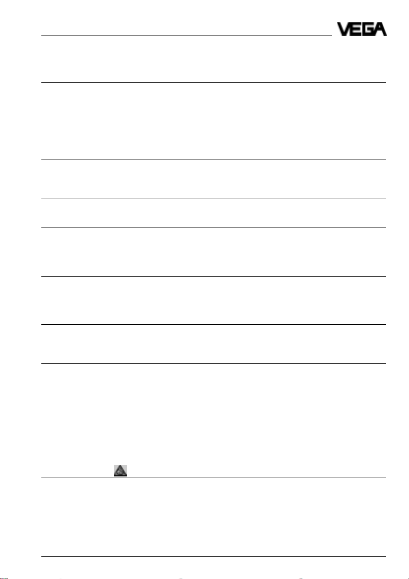
Connection lines
- supply and signal via one two-wire cable,
the line resistance depends on the supply voltage (see diagram).
Cross-section area of conductor generally 2,5 mm
Earth connection max. 4 mm
2
2
Cable entry 2 x M20 x 1,5 (cable diameter 5 … 9 mm)
Voltage limit
Ex-sensor
Voltage limit
not-Ex-sensor
Supply voltage
CE-conformity
VEGAFLEX sensors meet the protective regulations of EMVG (89/336/EWG) and NSR
(73/23/EWG).
The conformity has been judged acc. to the following standards:
EMVG Emission EN 50 081 - 1: 1992
Susceptibility EN 50 082 - 2: 1995
NSR EN 61 010 - 1: 1993
Display indication
Display scalable analogue and digital measured
value indication (option).
An external measured value indication, supplied by the sensor, can be mounted up to
25 m separated from the sensor.
10 VEGAFLEX 51V and 52V
Page 11

Product description / Technical data
Signal output VEGAFLEX 51V, 52V
Signal output digital output signal in two-wire technology
(VBUS)
Two-wire technology:
The digital output signal (measuring signal) is modulated to the power supply and further
processed in the signal conditioning instrument or in the processing system.
VEGAFLEX 51V and 52V 11
Page 12

Product description / Approvals
1.6 Approvals
VEGAFLEX sensors are approved for dustEx-Zone 10.
Note the attached approval documents when
using a sensor in Ex-area.
1.7 Dimensions
VEGAFLEX 51
Plastic housing Aluminium housing Aluminium housing (ExD)
Cable - steel
with gravity
weight
12 VEGAFLEX 51V and 52V
Cable - plastic
coated with
gravity weight
Cable - steel
with cable
loop
Cable - plastic
coated with
cable loop
Page 13

Product description / Dimensions
VEGAFLEX 52
Plastic housing Aluminium housing Aluminium housing (ExD)
Cable - steel
with gravity
weight
Cable - plastic
coated with
gravity weight
Cable - steel
with cable
loop
Cable - plastic
coated with
cable loop
Adjustment module MINICOM Cable loops
Adjustment module for plugging into series
50 sensors or into the external indicating
instrument VEGADIS 50
Cable - steel
VEGAFLEX 51V and 52V 13
Cable plastic
coated
Page 14

2 Mounting
2.1 Installation instructions
Lateral load
Note that the measuring cable is not subjected to strong lateral forces. Mount
VEGAFLEX to a position in the vessel where
no interfering influences such as e.g. of stirrers, filling openings etc. can occur (see fig.
2.1).
Fig. 2.1 Lateral load
Mounting / Installation instructions
Shortening of the measuring cable
The cable can be shortened afterwards.
Loosen the three pins on the gravity weight
(hexagon) and remove the pins. Pull the
cable out of the gravity weight.
To avoid splicing of the steel cable during
cutting, you have to tin the cable around the
cutting position with a copper bit or strongly
tighten the cable with a wire. Shorten the
cable with a metal cutting saw or a cutting-off
wheel by the requested length.
In case of isolated cables with gravity weight,
the isolation should be removed on a certain
length (see fig. 2.2).
VEGAFLEX 51 45 mm
VEGAFLEX 52 60 mm
In case of cable loops the cable should remain isolated.
Extraction forces
In case of strong extraction forces, e.g. during quick emptying or settling of solids, high
tensile loads can be caused.
When such an installation position is necessary, the cable should not be strained but
only equipped with a gravity weight as the
cable can more easily follow the product
movements. Note that the cable does not
touch the vessel wall.
Pressure
In case of gauge or low pressure in the vessel, the mounting boss should be sealed on
the thread. Use the attached seal ring. Check
if the seal ring is resistant against the medium.
14 VEGAFLEX 51V and 52V
Fig. 2.2 Shortening of the measuring cable
Page 15

Mounting / Installation instructions
Cable entries
When mounting outside, on cooled vessels or
in humid areas where cleaning is made e.g.
with steam or high pressure, the seal of the
cable entry is very important.
Use cable with a round cross-section area of
conductor and tighten the cable entry. The
cable entry is suitable for cable diameters of
5␣ mm to 9␣ mm.
Humidity from outside
To avoid humidity ingress, the connection line
to the housing should be looped directly
behind the cable entry to the bottom so that
rain and condensation water can drain off.
This is mainly valid for mounting outside, in
areas where humidity is expected (e.g. by
cleaning processes) or on cooled or heated
vessels (see fig. 2.3).
Fig. 2.3 Humidity
VEGAFLEX 51V and 52V 15
Page 16

Mounting / Installation instructions
Material cone
Note when installing VEGAFLEX into the vessel that material cones can be caused with
solids which can change the measured
value. We recommend to choose an installation place where the cable detects an average value of the material cone.
Dependent on the position of the filling and
emptying opening in the vessels, VEGAFLEX
should be installed appropriately. For compensation of measuring errors caused by the
material cone, you should install the cable at
a distance of d/6 from the vessel wall or vessel
installation. In any case keep a min. distance
of 300 mm.
3
1 Emptying
2 Filling opening
3 VEGAFLEX
16 VEGAFLEX 51V and 52V
1
2
Page 17

Mounting / Installation instructions
Straining
Generally the measuring result is only slightly
influenced when the gravity weight is in contact with the vessel wall.
Dependent on the kind of solid, the installation or the kind of filling, the cable can "float"
(fig. 2.4) despite of the gravity weight. The
solid can push the cable to the vessel wall or
to the top and wrong measured values are
caused.
In this case fasten the cable. When straining
the cable avoid strong cable forces. In our
pricelist you will find a spring as accessory
avoiding overloading of the cable.
Build-up
Generally build-up on the cable causes
changes of the measured value. If strong
build-up on the cable has to be expected, it
is recommended to use an isolated cable.
The higher surface quality avoids build-up.
Abrasion
In very abrasive products, e.g. the measurement of grit, use a measuring cable without
isolation.
Socket
If possible avoid long sockets.
Fig. 2.4 Cable electrode in solids
VEGAFLEX 51V and 52V 17
Page 18

Electrical connection / Connection and connection cable
3 Electrical connection
3.1 Connection and connection cable
Safety information
Ensure that the instrument is in currentless
condition. Always switch off the power supply before you carry out terminal work on the
radar sensors. Protect yourself and the instrument, especially when you use sensors
which do not work with low voltage.
Skilled staff
Instruments which are not operated with a
protective low voltage must only be connected by skilled staff.
Connection
For connection a standard two or four-wire
cable (sensors with separate supply) with
max. 2,5 mm2 can be used. Very often "Electromagnetic pollution" by electronic actuators,
energy lines and emitting systems is so
considerable that the two or four-wire cable
should be screened.
We recommend to use screened cable. This
screening prevents against future interferences (figure 3.1 a).
It is favourable to earth the screens on both
ends. However it must be noted that no earth
compensation currents flow via the sensor
cable screens (figure 3.1 b). Earth compensation currents can be avoided by connecting the cable screen in case of earthing on
both sides on one earthing side (e.g. in the
switching cabinet) via a capacitor (e.g.
0,1␣ µF; 250␣ V AC) to earth potential. Use a
very low impedance earth connection (foundation, plate or mains earth).
In dust-Ex-applications the screen should be
on one end.
Ex-protection
If an instrument is used in dust-Ex areas, the
appropriate regulations as well as the dustEx-certificate of VEGAFLEX for systems in
dust-Ex-areas should be noted.
Connection cable
Note that the connection cables must be specified for the expected operating conditions in
your systems. The cable must have an outer
diameter of 5␣ …␣ 9␣ mm (1/5 to 1/3␣ inch). Otherwise the seal effect of the cable entry will not be
ensured.
Cables for intrinsically safe circuits must be
marked blue and must not be used for other
circuits.
Earth conductor terminal
On VEGAFLEX sensors the earth conductor
terminal is galvanically connected with the
metal thread.
18 VEGAFLEX 51V and 52V
Page 19

Electrical connection / Screening
Earthing on one sensor side
Processing
Earthing on both ends (on the signal conditioning instrument via the potential
separating capacitor)
Fig. 3.1 a
≥ 0,1 µF
250 V AC
Processing
In dust-Ex-applications the screening should
only be made on one side. Due to the potential
difference earthing on both sides is not al-
Fig. 3.1 b
lowed.
VEGAFLEX 51V and 52V 19
Page 20

3.2 Connection of the sensor
• Loosen the closing screw on the upper
side of the sensor.
• Open the sensor cover.
• Remove the compression nut of the Pg
and shift the nut a little bit over the connection cable.
• Remove the rubber seal out of the Pg and
shift the seal over the connection cable.
• Remove the cover of the connection cable
over a length of approx. 10 cm.
• Loop the cable through the Pg into the
sensor.
Electrical connection / Connection of the sensor
• Connect the cable.
Push the white buckets of the spring
terminals with a small screwdriver and
insert the copper core of the connection
line into the terminal opening.
Check the position of the cables in the
terminal by slightly pulling.
• Fasten the compression nut on the Pg.
VBUS
To the indicating instrument in the
sensor cover or to the external indicating instrument VEGADIS 50
Two-wire sensor
M20 x 1,5
(diameter of the
connection cable
5…9␣ mm)
20 VEGAFLEX 51V and 52V
Page 21

Set-up / Connection of the indicating instrument VEGADIS 50
3.3 Connection of the indicating instrument VEGADIS 50
Loosen the 4 screws of the housing cover on
VEGADIS 50.
You can facilitate the connection procedure
by fastening the housing cover during connection on the housing by means of the
screws (figure).
Adjustment module
VEGADIS 50
Screws
VBUS
to VEGADIS 50
(use screened cable. See
fig. 3.1 a or fig. 3. 1 b)
T wo-wire sensor
M20x1,5
VEGAFLEX 51V and 52V 21
Page 22

4 Set-up
4.1 Adjustment structure
Series 50 sensors can be adjusted
- with PC (adjustment program VVO)
- with detachable adjustment module
MINICOM
- with a signal conditioning instrument
VEGAMET (V)
The sensors can only be adjusted with one of
the possibilities at the same time.
Independent whether you set-up a measuring system (unit of sensor and signal conditioning instrument VEGAMET or sensor and
processing system VEGALOG) with the
adjustment software VVO, with the signal
conditioning instrument or with the adjustment
module MINICOM, the adjustment procedure
is always the same:
- first of all configure a measuring system
in the menu "
- carry out the parameter adjustment of the
sensors in the menu "
Adjustment module MINICOM
With the adjustment module MINICOM you
adjust directly in the sensor or in the external
indicating instrument VEGADIS 50. The adjustment module MINICOM enables with the
6-key adjustment field with text display the
adjustment of the sensor in the same function
volume as with the adjustment program VVO.
Configuration
Instrument data
“ and then
“.
Set-up / Adjustment structure
Adjustment program VVO
With the adjustment program VVO (VEGA
Visual Operating System) on the PC you
adjust the sensors very comfortably. The PC
communicates via the interface adapter
VEGACONNECT␣ 2 with the sensor. The signal and supply line is therefore superimposed by a digital adjustment signal.
The PC can be connected to any position on
the cable or directly to the sensor.
Signal conditioning instrument
VEGAMET (V)
The signal conditioning instrument VEGAMET
enables with the 6-key adjustment field with
text display the parameter adjustment in the
same function volume as with the adjustment
program VVO on the PC.
22 VEGAFLEX 51V and 52V
Page 23

Set-up / Adjustment module MINICOM
4.2 Adjustment with adjustment module MINICOM
As with the PC, the sensor can also be adjusted with the small detachable adjustment
module MINICOM. The adjustment module is
therefore inserted into the sensor or the
external indicating instrument (optionally).
For the adjustment with adjustment module
also all adjustment options are available as
on the PC with adjustment program VVO.
All adjustment steps can be carried out with
the 6 keys of the adjustment module. A small
display gives you beside the measured
value a short information on the menu point or
the figure of a menu adjustment.
Adjustment elements
The adjustment module MINICOM is menu
orientated. The clear text indications on the
display lead through the menu. The functions
of the keys are described in the following.
OK-key (4)
With the OK-key adjustments can be confirmed.
When the symbol ▼ or is displayed, you can
move with the OK-key to the next lower menu
stage.
With the symbol there is no branch below
the menu point but only another menu point of
the appropriate function.
ESC-key (3)
With the Escape-key (ESC) you can dependent on the menu point interrupt an adjustment or a function or change to the next
higher menu stage.
E.g. to reach the top menu stage, push the
ESC-key several times.
+ and - key (2)
With the keys + and - you can modify the
values of the parameters or choose out of
several possibilities.
After pushing the first time, the value to be
adjusted flashes. The value will be modified
by further pushing the key.
Arrow keys (5)
With the keys > and < you can move within
the menu stage from one menu point to the
other.
Digital indication (1)
On the digital indication the actual measured
value is displayed during operation.
When you adjust the instrument, the clear text
indication displays the appropriate function.
▼
Branch out of which you can change to a
lower menu.
▼
This symbol informs you about a follow-
▼
ing safety enquiry.
▼
▼
▼
▼
2
1
5
VEGAFLEX 51V and 52V 23
3
4
Page 24

Set-up / Adjustment module MINICOM
Adjustment steps
On the following pages you see the menu
plan of the adjustment module MINICOM.
Set-up the sensor in the following sequence.
The numbers correspond to the sequence of
a set-up. The numbers are stated near the
appropriate menu points in the menu plan on
the following pages.
1. Adjustment
2. Conditioning
3.Outputs
4. Operating range
5. Meas. conditions
6. Indication of the useful and noise level
1. Adjustment
Under the menu point "
form the sensor with which span it should
work.
Max.
Adjustment
100 % (distance to the medium
0,300 m) correspond to
1200 l, e.g. 20 mA
“ you in-
Span
Adjustment without medium
• Enter with the "+“ and "–“ key the distance to the medium your sensor has at
0 % filling (example: 5,850 m)
If you do not know the distance, you have
to sound.
• Enter the distance to the medium which
your sensor has at 100 % filling.
Key Display
Sensor
m(d)
4.700
Para-
OK
OK
OK
OK
meter
adjustment
Adjustment
without
medium
Adjustment
in
(Min-adjustment)
m(d)
0.0 %
at
m (d)
XX.XXX
1)
1)
In case of two values which can be modified
you can move with the "OK“-key to the second value.
Min.
0 % (distance to the medium
5,850 m) correspond to
456 l, e.g. 4 mA)
Adjustment with medium
Fill the vessel e.g. to 10 %, enter in the menu
"
Min-adjustment
“ with the "+“ and "–“ keys
10 % and confirm with the "OK“-key. Then fill
the vessel e.g. to 80 % or 100 %, enter in the
menu "
You can carry out the adjustment without or
with medium. Generally you will carry out the
keys 80 % or 100 % and confirm with the
"OK“-key.
adjustment without medium as you can adjust
without vessel filling.
24 VEGAFLEX 51V and 52V
Max-adjustment
“ with the "+“ and "–“
with
medium
Max.
Min.
adjust
adjust
at %
at %
XXX.X
XXX.X
Page 25

Set-up / Adjustment module MINICOM
2. Conditioning
Under the menu point "
choose the distance at 0 % and at 100 %
filling. Then you enter the parameter and the
appropriate unit as well as the decimal point.
• Enter in the menu window "
sponds
“ the value of the 0 %-filling. This
will be e.g. "80“ for 80 l.
• Confirm with "OK“.
• With the arrow key you change to the
100␣ % menu. Enter here the value of your
parameter corresponding to a 100 %filling. E.g. "1200“ for 1200 l.
• Confirm with "OK“.
• Choose if necessary a decimal point.
Note that max. 4 digits can be shown.
• In the menu "
parameter (mass, volume, distance…).
• In the menu "
cal unit (kg, l, ft3, gal, m3 …).
• With the ESC-key you change to the
superimposed menu stage. With the
arrow key you choose the next menu
point.
• In the menu
between three standard linearisation
curves.
Preadjusted is a linear dependence between percentage value of the product
distance and the percentage value of the
filling volume.
You can choose between linear, spherical
tank and cylindrical tank. The adjustment
of a user programmable curve is only
possible with the PC and the adjustment
program VVO.
• In the menu point
can adjust a delay for the signal output.
Conditioning
0 % corre-
prop. to
“ you choose the
Unit
“ you choose the physi-
"Lin. curve“
you can choose
"Integration time“
“ you
you
3. Outputs
Under the menu "
display and determine which parameter
should be provided by the sensor display.
Outputs
“ you can scale the
4. Operating range
Without special adjustment, the operating
range corresponds to the measuring range.
The measuring range was already adjusted
with the Min/Max-adjustment. It is generally
suitable to choose a slightly bigger operating
range (approx. 5 %) than the measuring
range (span).
Example:
Set Min/Max-adjustment: 0,300 … 5,850 m;
operating range to approx. 0,250 … real
cable length.
When you shorten the cable, you have to
define the cable length again.
5. Meas. conditions
With these functions you can enter the ambient conditions in the vessel.
(see menu plan)
6. Useful and noise level
In the menu
tion on the signal quality of the product echo.
The higher the "
the measurement.
Ampl.: Means amplitude of the product echo
S-N: Means Signal-Noise (useful level
The higher the S-N-value (useful level minus
noise level), the better the reliability:
> 50 dB Measurement very good
40 … 50 dB Measurement good
20 … 40 dB Measurement satisfactory
15 … 20 dB Measurement sufficient
< 15 dB Measurement bad
"Info“
you get important informa-
S-N
“-value, the more reliable
in dB (useful level)
minus noise level)
VEGAFLEX 51V and 52V 25
Page 26

Set-up / Menu plan of the adjustment module MINICOM
Menu plan of the adjustment module MINICOM
Sensor
m(d)
4.700
Parameter
adjustment
Sensor
optimize
Sensor
Tag
Sensor
Meas.
environ
ment
Operating
range
Begin
m (d)
0.50
FLEX51
When switching on, the sensor type and the
V
software version are displayed for a few seconds.
0.50
4.
Cable
length
m (d)
6.00
Meas.
condit
ions
Condition
Solid
5.
fast
change
No
agitated
sur
face
No
Low DK
value
No
Empty
vessel
pro
file
Create
new
Meas.
dist.
m (d)
X.XX
Create
new
Now!
OK ?
Learning !
Update
Meas.
dist.
m (d)
X.XX
Update
now!
OK ?
Learning !
Delete
Delete
Now!
OK ?
Deleting !
Adjustment
Adjustment
in
m(d)
1.
0%
at
m (d)
XX.XXX
100 %
at
m (d)
XX.XXX
Note:
Set-up the sensor in the sequence of the
numbers.
Signal
conditioning
Scaling
0 %
corresponds
XXXX
2.
Lin.
curve
Linear
100 %
corresponds
XXXX
Integr
ation
time
Decimalpoint
888.8
0 s
prop.
Unit
to
Mass
kg
26 VEGAFLEX 51V and 52V
Page 27

Set-up / Menu plan of the adjustment module MINICOM
Add’l
functions
With these keys you move in
the menu field to the left, the
right, top and bottom.
ESC
OK
Reset
to default
Reset
Now !
OK ?
Reset
runs!
Outputs
Sensor
displ.
act.
dist.
m (d)
4.700
Ampl.:
XX dB
S-N:
XX
dB
Info
Reset
to de
fault
Reset
Now !
OK ?
Reset
runs !
Language
English
Meas.
unit
m (d)
6.
Sensor
Tag
Sensor
Sensor
type
FLEX51
V
Serial
number
1094
0213
Softw.
Vers.
1.00
Softw.
date
15.09.
1997
dist.
m (d)
4.700
XX dB
S-N:
XX
dB
Ampl.:
act.
3.
Bolt print figures are sensor or
measured value information and
cannot be modified in this position.
The menu points in white letters
stand for figures which can be
modified with the or key and
saved with the key.
OK
prop.
to
Distance
act.
dist.
m
X,XX
fast
change
Yes
VEGAFLEX 51V and 52V 27
Page 28

4.3 Adjustment with PC
Connection
The PC with the adjustment program VVO
(VEGA Visual Operating from version 2.50)
can be connected
- to the sensor or
- to the signal line.
PC on the sensor
For connection of the PC to the sensor you
require the interface adapter VEGACONNECT 2. Insert VEGACONNECT 2 into the
provided CONNECT-sockets in the sensor.
PC on the signal line
Connect the two-wire line of VEGACONNECT
2 to the signal or supply line of the sensor.
When the resistors of the systems (DCS,
current source etc.) connected to the signal/
supply line are less than 250 Ω, a resistor of
250 … 350 Ω should be looped into the signal/supply line during adjustment.
The digital signals modulated to the signal
line would be extremely damped via the low
system resistors (i.e. short-circuited) so that
the communication with the PC would be
interfered.
Set-up / Adjustment with PC
When you have connected the PC with the
operating software VVO to your measuring
system,
• switch on the power supply of the connected sensor.
In the first 10 … 15 seconds the sensor takes a
current of approx. 22 mA (self check) and
takes then a level proportional or distance
proportional current.
• Start the adjustment software VVO
(VEGA Visual Operating) on your PC.
• In the entrance window you choose with
the arrow keys or the mouse the point
Planning
You should only choose
you are entitled to modify instrument
parameters. Otherwise choose
or
In the window
asked for the name and the password.
• For set-up (
VEGA and under password also: VEGA.
It does not matter if you use capital or
small letters.
VVO determines automatically the type of the
connected sensor and shows shortly with
which sensor a connection exists.
and click to OK.
Maintenance
planning
Planning,
.
User identification
) enter under name:
when
Operator
you are
When you get no sensor connection, check
the following:
- The supply voltage should be at least
20 V.
- When connecting VEGACONNECT 2
directly to the sensor line, the load resistor should be 250 … 350 Ohm.
- You have to use a VEGACONNECT 2.
VEGACONNECT 2
28 VEGAFLEX 51V and 52V
Older versions of VEGACONNECT are
not compatible.
Further information on the adjustment with PC
and the adjustment software VVO is stated in
the operating instruction of the adjustment
software VEGA Visual Operating (VVO).
Page 29

Set-up / Adjustment with PC
Special functions
When a VEGAFLEX-sensor is determined,
you can choose with the adjustment software
VVO some special functions of VEGAFLEX.
Under the menu point Instrument data/Parameter adjustment you can choose the sensor optimisation.
Here you find all special functions of
VEGAFLEX:
- meas. environment
- echo curve
Measuring environment
Measuring conditions
Choose in this menu if you want to measure in
solids or liquids.
When you want to measure a product the
DK-value of which is below 2, you can increase the sensitivity of the sensor.
Echo curve
The echo curve shows all reflections of the
guided microwave signal.
This means not only the product signal is
shown but also false signals caused, e.g. by
vessel installations.
Generally the sensor determines the biggest
amplitude as useful echo.
You see a black arrow above the highest
amplitude. When you click to "Display info“, a
small window is displayed, listing the detailed
values of the selected echo.
Operating range
With this command you can limit the operating range of the sensor or enter the cable
length again after shortening the cable.
Carry out the adjustment before modifying
the operating range as a later adjustment can
overwrite the values of the operating range.
The right part of the graphics shows the
operating range, the left part the adjustment.
When e.g. you cannot fill your vessel completely, you can limit the operating range.
VEGAFLEX 51V and 52V 29
Zoom / Unzoom
After activation of these two functions, you
can either zoom or unzoom the curve with the
left mouse key.
When you activate "Zoom“, you can choose
the requested part of the figure by pushing
the left mouse key and drawing a frame.
Page 30

The following curves can be displayed:
Raw value curve (red)
The red curve means the absolute signal
which the receiver of VEGAFLEX detects.
Beside the useful echo this curve also contains false signals.
The highest amplitude is detected as useful
echo. Check by sounding if the value of the
useful echo corresponds to the actual distance to the level.
When both values do not correspond, you
have to gate out the dominant false echoes
with the function "Empty vessel profile“.
Set-up / Adjustment with PC
Start
When clicking to "Start“, the echo curve will
be updated continuously. With "Stop“ you can
terminate the update.
Vessel profile (blue)
This curve shows in normal condition the
actual empty vessel profile.
For gating out of false echoes you can modify
the blue curve of the vessel profile with the
function "Empty vessel profile".
Reference line (green)
All amplitudes of the red curve which are
below the green reference line, are suppressed (ringing, noise, false echoes etc.).
All amplitudes above this line are possible
echoes which are processed by the software.
Logarithmic raw value curve (black)
The curve shows the difference between raw
value curve (red) and reference line (green).
For this curve the scale on the right page
(dB) is valid.
Documentation
When clicking to the button "Documentation“
the actual echo curve will be saved.
Echo data
When clicking to the button "Echo data“, a
window is displayed where all echoes detected by the sensor with DB-information and
a probability processing are listed.
Empty vessel profile
With the functions in this window you can
gate out false echoes.
The blue empty vessel profile curve in the
echo curve window shows the actual empty
vessel profile.
Determine the level by sounding. When the
sensor has determined instead of the
sounded level a false echo as most probable
echo, you can gate the echo out. Choose the
function "Create new“. Enter the measured
distance to the medium. All false echoes, in
the range to the adjusted distance, are automatically gated out. Note that then also the
blue curve of the empty vessel profile
changes.
.
With "Update“ you can extend the empty
vessel profile when new false echoes occur
with reducing level.
When you want to delete the existing empty
vessel profile, click to "Cancel“.
30 VEGAFLEX 51V and 52V
Page 31

Set-up / Adjustment with signal conditioning instrument
4.4 Adjustment with signal conditioning instrument
VEGAMET (V)
VEGAFLEX 51V and 52V sensors can be
adjusted with the following signal conditioning instruments:
- VEGAMET 514V
- VEGAMET 515V
- VEGAMET 614V
For adjustment the digital signal conditioning
instruments VEGAMET (V) are provided with
a 6-key adjustment field with display. The
parameter adjustment can be therefore carried out in clear text dialogue.
The adjustment structure corresponds to the
adjustment on the adjustment module MINICOM.
The complete menu plan of the signal conditioning instrument is included in the appropriate operating instruction of the signal
conditioning instrument used.
VEGALOG 571
VEGAFLEX sensors can be also adjusted
with the processing system:
- VEGALOG 571
VEGALOG 571 processing system can only
be adjusted with the PC in conjunction with
the processing software VVO (VEGA Visual
Operating).
The adjustment of VEGALOG is described in
the operating instruction of the adjustment
software VVO.
VEGAFLEX 51V and 52V 31
Page 32

5 Diagnosis
5.1 Simulation
For simulation of a certain filling, you can
enquire the function "Simulation" on the adjustment module MINICOM, in the software
program VVO or in the signal conditioning
instrument VEGAMET (V).
You simulate a certain measured value. Note
that connected instruments such as e.g. a
DCS react according to their adjustments
and probably activate alarm signals or system functions.
5.2 Error removal
Error Error removal
E 013 Sensor does not find - Message is displayed during feeding
level echo phase.
- When the message remains, the DK-value
of the medium can be too low.
Check the useful and noise level.
See 4.2 Adjustment with adjustment module
MINICOM / 6. Useful and noise level.
When the message still remains, carry out
a new adjustment.
Diagnosis
E 017 Adjustment span too small Carry out a new adjustment.
E 036 Software-Update incorrect Return the instrument for repair.
E 040 Hardware failure / Check all connection lines.
electronics defect Contact our service department.
32 VEGAFLEX 51V and 52V
Note that the difference between min. and
max.-adjustment is at least 10 mm.
Page 33

Notes
VEGAFLEX 51V and 52V 33
Page 34

Notes
34 VEGAFLEX 51V and 52V
Page 35

Notes
VEGAFLEX 51V and 52V 35
Page 36

VEGA Grieshaber KG
Am Hohenstein 113
D-77761 Schiltach
Phone (0 78 36) 50 - 0
Fax (0 78 36) 50 - 201
e-mail info@vega-g.de
The statements on types, application, use and operating conditions of
the sensors and processing systems correspond to the actual knowledge at the date of printing.
Technical data subject to alteration.
2.23 227 / March ’99
 Loading...