

Page 1
Operating Instructions
PROF I
BUS
PROCESS FIELD BUS
VEGAFLEX 51P and 52P (Profibus PA)
Level and Pressure
Page 2

Contents
Safety information
Please read this manual carefully, and also take
note of country-specific installation standards
(e.g. the VDE regulations in Germany) as well
as all prevailing safety regulations and accident prevention rules.
For safety and warranty reasons, any internal
work on the instruments, apart from that involved in normal installation and electrical connection, must be carried out only by qualified
VEGA personnel.
2 VEGAFLEX 51P and 52P
Note Ex area
Please note the approval documents (yellow
binder), and especially the included safety
data sheet.
Page 3

Contents
Contents
Safety information ........................................................................ 2
Note Ex area ................................................................................ 2
1 Product description
1.1 Function ................................................................................. 4
1.2 Application features ............................................................. 5
1.3 Adjustment media ................................................................ 5
1.4 Profibus output signal .......................................................... 6
1.5 Type code ........................................................................... 10
1.6 Bus configuration ............................................................... 11
1.7 Technical data ..................................................................... 14
1.8 Approvals ........................................................................... 17
1.9 Data format of the output signal ........................................ 17
1.10 Dimensions ......................................................................... 18
2 Mounting
2.1 Installation instructions ...................................................... 20
3 Electrical connection
3.1 Connection – Connection cable – Screening ................... 23
3.2 Sensor address ................................................................. 27
3.3 Connection of the sensor .................................................. 29
3.4 Connection of the external indicating instrument ............ 30
4 Setup
4.1 Adjustment media .............................................................. 31
4.2 Adjustment with the adjustment module MINICOM ........ 32
4.3 Adjustment with the PC ...................................................... 38
5 Diagnostics
5.1 Simulation ............................................................................ 43
5.2 Function diagram ............................................................... 43
5.3 Error rectification ................................................................ 48
5.4 PA parameters .................................................................... 49
VEGAFLEX 51P and 52P 3
Page 4

1 Product description
Product description
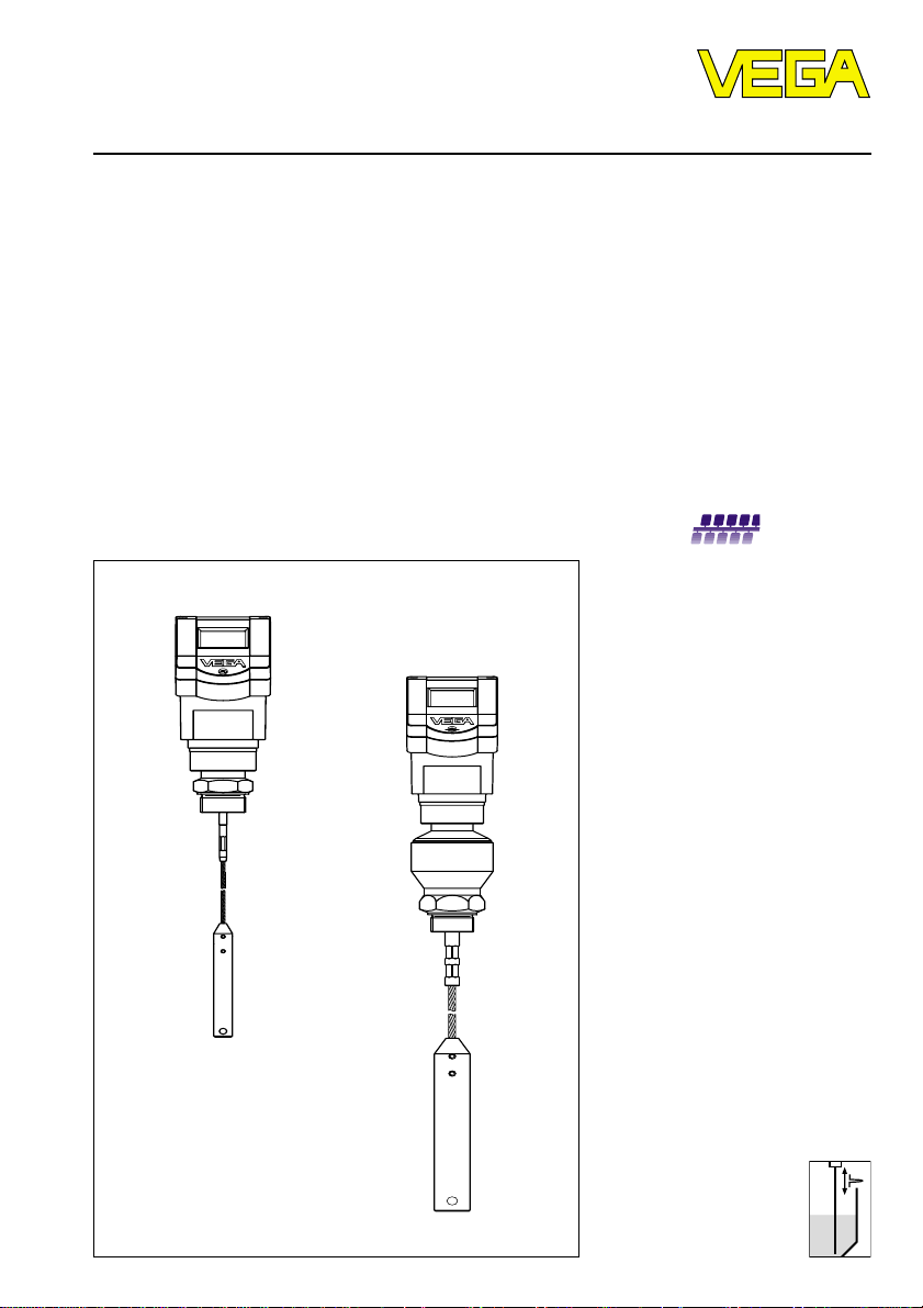
1.1 Function
High frequency microwave impulses are
guided along a steel rope. When reaching
the product surface, the microwave impulses
are reflected. The running time of the impulses is processed by the integrated electronics and outputted as level.
The sensors measure the levels of all kinds of
solids. Density, conductivity, dust generation
and dielectric constant of the product do not
influence the measurement. Also, the changing features of a solid do not influence the
measured value.
Lime, cement, cereals, plastic granules, flour,
gravel - VEGAFLEX microwave sensors
solve difficult application problems in solids.
The level is also detected reliably in products
with varying moisture content or fluctuating
dielectric constant. High, narrow vessels or
steep material cones in which non-contact
measuring principles did not deliver optimum
measuring results, can be measured without
problem with VEGAFLEX.
VEGAFLEX 51 and 52 differ mainly in the
thickness of the measuring cable.
VEGAFLEX 51 has a cable with 4 mm diameter and is available up to a length of
10 m.
• Measuring range up to 20 m with low min.
distance.
• Up to 32 sensors (Ex area: 8 sensors) can
be connected via one two-wire cable.
• Two-wire sensor, supply and digital measuring signal via one two-wire cable.
• Unaffected by application conditions such
as:
- dust and noise generation
- humidity changes
- varying products
- buildup
• Adjustment without vessel filling or emptying.
• Unaffected by vessel material, e.g. metal,
concrete, plastic etc.
• Measuring cable or gravity weight must not
be insulated from the vessel.
The cable of VEGAFLEX 52 has a diameter of
8 mm and can have a length of up to 20 m.
Due to the stronger cable it is suitable for
solids subjected to higher extracting forces.
4 VEGAFLEX 51P and 52P
Page 5
Product description
1.2 Application features
Applications
• Level measurement in solids.
• Measurement also in vacuum.
• All slightly conductive substances and all
products with a dielectric constant er > 1.7
can be measured.
• Measuring ranges
VEGAFLEX 51 0 … 10 m
VEGAFLEX 52 0 ... 20 m
Rugged
• High-resistance materials: PA, 1.4401.
Precise and reliable
• Resolution 1 mm.
• Unaffected by noise, steam, dust, gas
compositions and inert gas stratifications.
• Unaffected by varying density.
• Measurements under pressure up to
16 bar and at product temperatures up to
120°C.
Communicative
• Integrated measured value display.
• Optional display and adjustment module
separate from the sensor.
• Adjustment from the PLC level.
Approvals
• StEx Zone 10
• Ex Zone 0
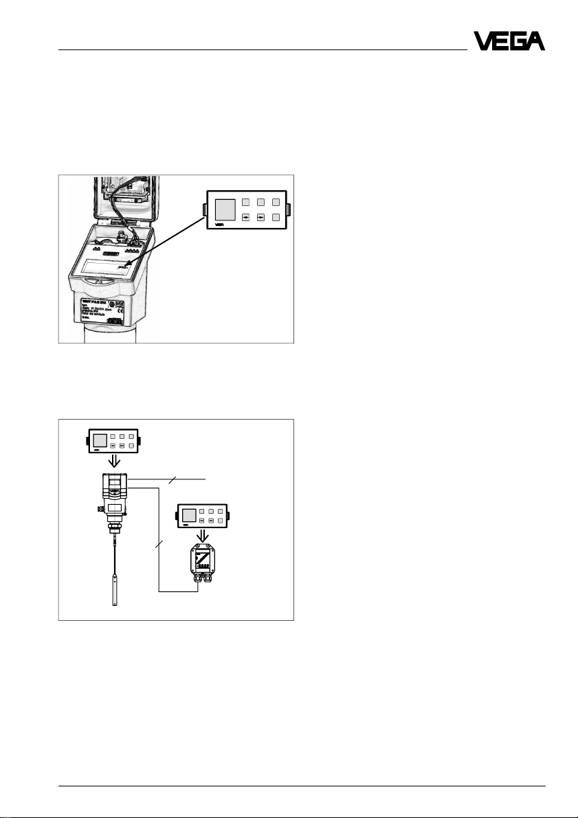
1.3 Adjustment media
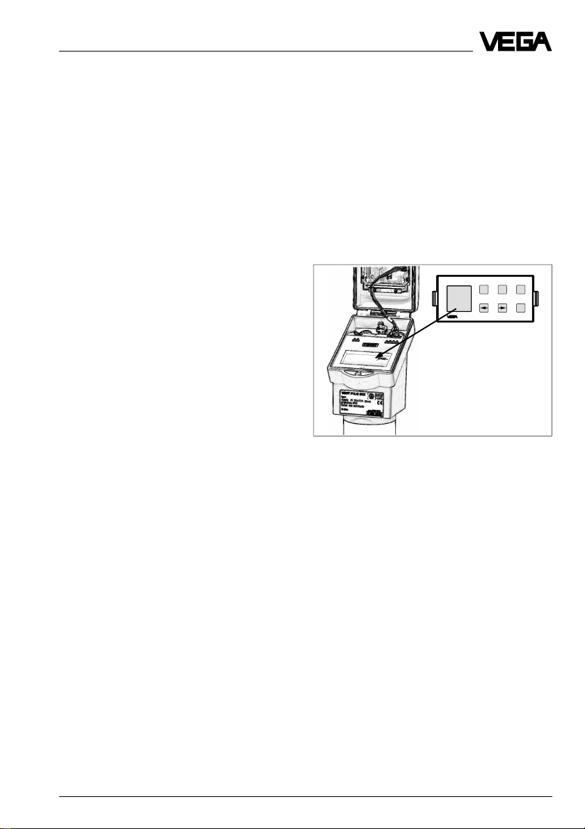
Adjustment with the adjustment module
MINICOM
With the 6-key adjustment module MINICOM
(3.2 cm x 6.7 cm) the adjustment can be
carried out in clear text dialogue. The adjustment module can be plugged into the VEGAFLEX or into the external indicating
instrument VEGADIS 50. It also possible to
adjust VEGAFLEX from the external indicating instrument VEGADIS 50.
Tank 1
m (d)
12.345
Pluggable adjustment module MINICOM
Adjustment with PC
The setup and adjustment of the VEGAFLEX
sensors can be done on the PC with the
adjustment program VVO (VEGA Visual Operating) under Windows®.
The software leads quickly through adjustment and parameter setting by means of
pictures, graphics and process
visualisations.
ESC
+
-
OK
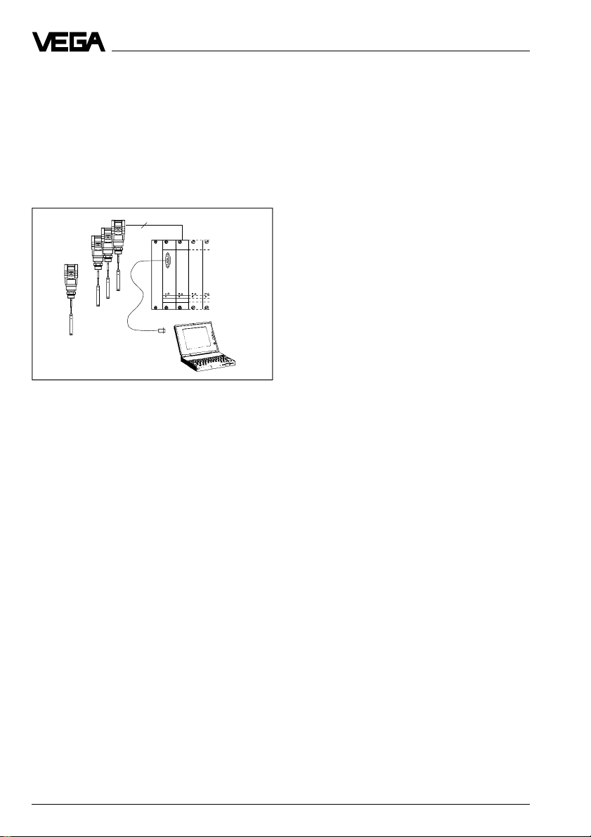
The adjustment program VVO from VEGA
makes the full range of functions of VEGA
sensors accessible and, if necessary, can
update the entire sensor software. For this
reason, the adjustment program must be
installed on a PC which is equipped with a
Profibus Master Class 2 interface card
(Softing) (see figure under "1.4 Profibus
output signal").
VEGAFLEX 51P and 52P 5
Page 6
Product description
The PC with the Profibus interface card can
be connected directly at any location to the
DP bus by means of the standard RS 485Profibus cable.
The adjustment and parameter data can be
saved with the adjustment software on the
PC. On request, the adjustment can be also
transferred to other sensors.
2
......
VEGALOG
VEGALOG
571 CPU
571 EA
1 ... 15
1 … 32
Adjustment with the PC and the standard cable
RS 232 on the VEGALOG processing system
1.4 Profibus output signal
As a process automation bus, Profibus PA
enables power supply over the bus. Up to 32
sensors can be operated on a shielded twowire cable that carries both power supply
and measuring signal. In Ex areas, up to ten
sensors can be connected from the PA level
to one two-wire cable (EEx ia).
Bus structure
The DP and PA bus consists of up to 126
master and slave participants. Data are always exchanged from point to point, with the
data traffic being exclusively controlled and
checked by master devices. Communication
is carried out according to the Token-Passing
procedure. This means that the master holding the token can contact the slaves, give
instructions, enquire data and cause the
slaves to receive and transmit data. After the
work is done or after a predetermined time
interval, the token is passed on by the master to the next master.
Master-Class 1
is the actual automation system, i.e. the process control computer or the PLC that enquires and processes all measured values.
Master-Class 2
One or several Master-Class 2 can operate in
a Profibus network. As a rule, Master-Class 2
devices are engineering, adjustment or visualisation stations. The VEGA adjustment software VVO (VEGA Visual Operating) operates
as Master-Class 2 participant on the DP bus
and can work on an engineering PC, on an
adjustment PC or on the process control
computer and can access any VEGA sensor
on the PA level.
6 VEGAFLEX 51P and 52P
Page 7

Product description
Profibus adjustment structure
In the Profibus environment, there are different adjustment concepts and adjustment
tools which often differ considerably from
manufacturer to manufacturer. From the user’s point of view, a manufacturer-independent adjustment program which could be
operated directly on the Profibus DP, but also
at a central point (e.g. the engineering station
or the process control), would be ideal.
In the past, only the program "SIMATIC PDM",
based on the HART® adjustment structure,
could fulfil this wish. However, this program
also has the limitations common to HART®. As
with HART®, the availability of an instrumentspecific database for a comprehensive adjustment with PDM (Process Device Managing) is a requirement. Otherwise, only the
basic instrument functions such as adjustment will be available. In the PDM environment, this instrument-specific database is
called EDD (Electronic Device Description),
in complete analogy to the HART® environment which, except for the VEGA-HART
instruments, also requires a DD (Device
Description) for each sensor.
®
VEGAFLEX 51P and 52P 7
Page 8
Product description
Adr. 21
SPS
Adr. 22
VVO
3
PA-
Adr. 23
Master-Class 1
Adr. 1
DP-Bus
Adr. 24
DP interface card as MasterClass 2 (e.g. Softing)
Adr. 10
3
Adr. 57
Segment coupler
Adr. 25 … 56
2
(max. 32 participants)
Adr. 58
Adr. 60
Adr. 59
Adjustment of the VEGAFLEX sensors from the process control via a Profibus interface card in the process
control computer or in an additional PC. The adjustment software VEGA Visual Operating (VVO) accesses via
the interface (interface card) the sensors bidirectionally.
8 VEGAFLEX 51P and 52P
Page 9
Product description
Adjustment with adjustment module
MINICOM
With the small (3.2 cm x 6.7 cm) 6-key adjustment module with display in the sensor,
the sensor-relevant adjustments can be carried out directly on the sensor.
Tank 1
m (d)
12.345
Detachable adjustment module MINICOM
The adjustment module can be plugged into
the sensor or into the optional, external indicating instrument.
ESC
+
-
Tank 1
m (d)
12.345
OK
2
PA-Bus
ESC
+
-
OK
Adjustment with the SIMA TIC PDM adjustment program
For adjustment of all essential functions of the
VEGA sensor with the adjustment station
SIMATIC PDM from Siemens, a so-called
EDD is required. Without this EDD, only the
basic functions such as min./max. adjustment
or the integration time can be adjusted with
the PDM adjustment program. Further important adjustment functions, such as input of
measuring environment data or false echo
storage, are not available without EDD. After
integration of the EDD files in the Simatic PDM
adjustment software, all important adjustment
functions are accessible. If it is not at hand,
the obligatory GSD (instrument master file)
as well as the EDD (Electronic Device Description) necessary for PDM can be
downloaded from the VEGA-Homepage
(http://www.vega.com).
ESC
+
-
Tank 1
m (d)
12.345
OK
4
max. 25 m
Adjustment with detachable adjustment module. The
adjustment module can be plugged into the sensor or
the external indicating instrument VEGADIS 50.
The sensor can be adjusted with the adjustment module MINICOM and basic functions
can be set. Beside the measuring conditions
and the simulation mode, the Profibus address can also be adjusted and a false echo
storage can be carried out, see "4.2 Adjustment with MINICOM".
VEGAFLEX 51P and 52P 9
Page 10
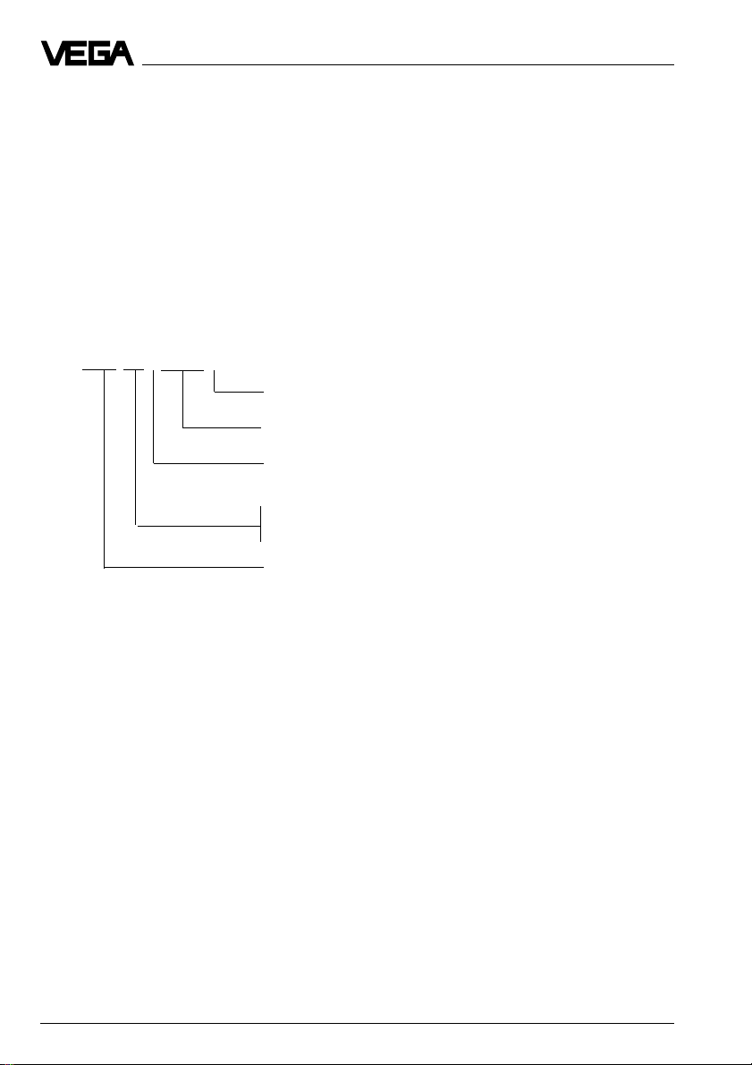
1.5 Type code
The second figure of the type name, e.g.
VEGAFLEX 5[1]… distinguishes the instruments acc. to the stability of the cable.
The letter, e.g. VEGAFLEX 51[P] indicates
the output signal:
K stands for an analogue 4 … 20 mA output
signal (compact instrument)
V stands for a digital output signal (VBUS).
P stands for a digital output signal with Profibus PA
VEGAFLEX XX P EXS.X G
G - Connection to segment coupler Profibus PA
Dust Ex approved
P - Digital output signal for connection to
Profibus PA
Type 51: Instrument series with 4 mm cable
Type 52: Instrument series with 8 mm cable
Measuring technology (FLEX for guided microwave)
Product description
10 VEGAFLEX 51P and 52P
Page 11

Product description
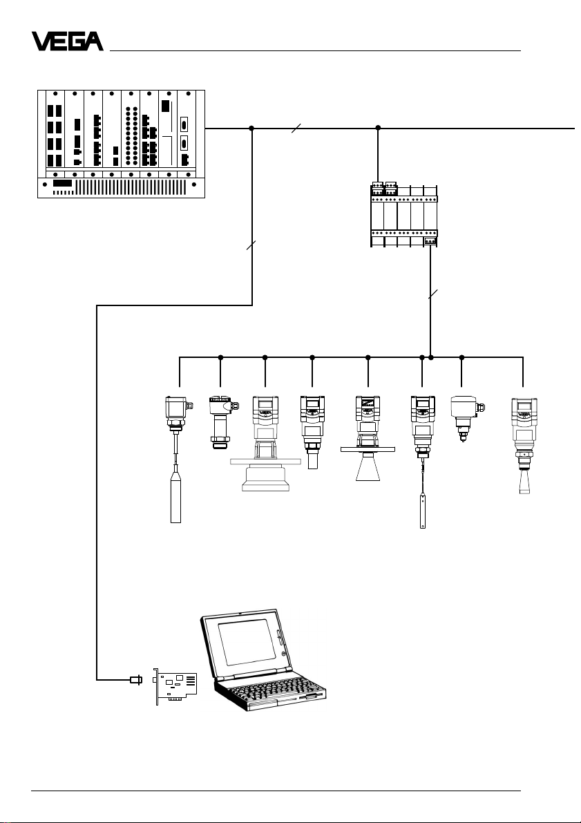
1.6 Bus configuration
The type of sensor you use depends on the
process requirements and mounting conditions, as well as on the requirements of your
control, regulative, or process control system.
VEGAFLEX 51P and 52P Profibus sensors
are sensors for use in Profibus PA environment. Profile 3 has been implemented in the
sensors. A measuring system consists of
one or several sensors, one or several segment couplers and one DP master computer,
such as e.g. a S7 PLC with Profibus interface
or a process control system with Profibus
DP-Master-Slot. The processing unit, e.g. the
PLC, evaluates the level-proportional, digital
measuring signals in a number of evaluation
routines and puts them to use process-specifically.
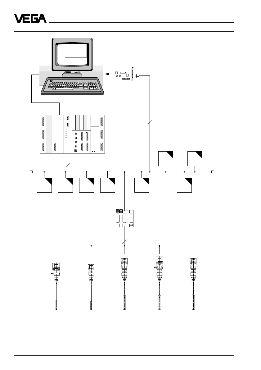
On the following two pages you will find a
schematic of the bus configuration.
The automation system as Master-Class 1
takes over the complete bus control. It reads
out all signals cyclically and, if necessary,
gives instructions to the participants (e.g.
sensors). In addition, further master systems
(e.g. visualisation systems or adjustment
tools) can be connected to the DP bus.
These systems operate as so-called MasterClass 2 participants. Like the Master-Class 1
system, they can read out signals, give instructions and operate in acyclical mode.
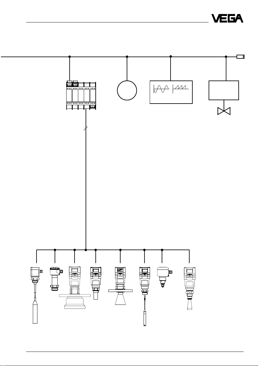
A DP bus does not allow power supply via
signal cable, whereas the PA bus does. Both,
DP and PA, require at least one screened
two-wire cable. The DP bus can additionally
have up to 8 cores (screened), some of
which can be supply cables.
Each participant on the bus must have an
address. The addressing covers both bus
levels. A Profibus DP system can have max.
126 participants, including all participants on
the PA level. In practice, each Master-Class 1
computer gets address 1 and the MasterClass 2 computers address 10 … 20. As a
rule, the slaves or participants get the addresses 21 … 126. On the Profibus PA level,
max. 32 sensors are possible on one PA
segment coupler.
Ex environment
In Ex environment, intrinsically safe (EEx ia)
PA sensors are used with Ex segment couplers. Generally, the number of PA sensors
on a segment coupler (Ex or non Ex) depends on the current requirement of the
sensors and on the current supplied by the
segment coupler. Segment couplers for
EEx ia environment provide 90 … 110 mA.
The number of sensors results from the sum
of:
- the basic current intake of all sensors
- plus 9 mA communication signal
- plus the leakage currents of all sensors
- plus a recommended current reserve
(approx. 10 mA)
The min. basic current has been set at 10 mA
according to the Profibus specification.
VEGA Profibus sensors constantly consume
a basic current of 10 mA and operate without
leakage current requirement, so that in Ex
environment, up to ten VEGA sensors can be
operated on one segment coupler.
VEGAFLEX 51P and 52P 11
Page 12
Address 1
Product description
2…8
Segment
coupler
PLC/DCS
Address
21...52
3
2
Profibus PA
21 22 52
1 … 32 sensors
(Ex: 1 … 10)
Master-Class 2
interface card
12 VEGAFLEX 51P and 52P
Address 10
Page 13
Product description
Profibus DP
Segment
coupler
Address
53...84
M
Address
85
3~M
Address
86
2
Profibus PA
53 54 84
Address
87
1 … 32 sensors
VEGAFLEX 51P and 52P 13
Page 14

Technical data
1.7 Technical data
Power supply
Supply voltage 9 … 32 V DC)
(output voltage UO of the segment dependent on the segment coupler used
coupler) see PA specification, e.g.
- non Ex e.g. 22 V DC (nominal voltage of the segment
- Ex 13.5 V DC nominal voltage of the segment
Current consumption constant 10 mA (no leakage current output)
Cable load dependent on the segment coupler, see
Measuring range
VEGAFLEX 51 0.3 … 10 m
VEGAFLEX 52 0.3 … 20 m
Output signal
digital (Profibus) two-wire technology:
Integration time 0 … 999 seconds (adjustable)
coupler) max. 32 sensors on one two-wire
cable
coupler max. 10 sensors on one two-wire
cable (typical 8 sensors)
technical data of the segment couplers and
Profibus specification
the digital output signal (meas. signal is
modulated onto the power supply and is further
processed in the PLC or in the process control
Adjustment
- adjustment software VEGA Visual Operating on Master-Class 2 PC
- adjustment module MINICOM in the sensor or in the external indicating instrument
(optional)
- process adjustment interface PACTwareTM (VVO as subprogram)
- SIMATIC PDM in conjunction with Electronic Device Description (EDD)
Accuracy
1)
(under reference conditions acc. to IEC 770 - relating to the max. measuring range)
Linearity error < 0.1 %
Temperature drift 0.015 %/10 K
Characteristics linear
Deviation in characteristics including
linearity, reproducibility and
hysteresis (determined acc. to the
limit point method) better than 0.05 %
Average temperature coefficient of the
zero signal 0.06 %/10 K
Resolution general max. 1 mm
Resolution of the output signal 0.005 % or 1 mm
1)
Similar to DIN 16 086, reference conditions according to IEC 770, e.g.
temperature 15°C … 35°C; moisture 45 % … 75 %; pressure 860 mbar … 1060 mbar
3)
The adjustment time (also actuating time, response time or adjustment period) is the time the sensor
requires to output the correct level (with max. 10% deviation) after a quick level change.
14 VEGAFLEX 51P and 52P
Page 15
Technical data
Characteristics
Min. span between full and empty adjustment
- digital output signal 10 mm
Adjustment time
2)
> 1 s (depending on the parameter setting)
Measuring range begin 300 mm below the seal surface
Measuring range end upper edge of the gravity weight or
the cable loop
Ambient conditions
Vessel pressure -1 … 16 bar
Ambient temperature on the housing -40°C … +60°C
Process temperature -40°C … +120°C
Storage and transport temperature -60°C … +80°C
Protection IP 66/IP 67 (meets both protections)
Protection class
- two-wire sensor II
Overvoltage category III
Max. tensile load
- cable ø 4 mm 5 KN
- cable ø 8 mm 20 KN
Ex technical data
StEx Zone 10
Ex Zone 0
The permissible operating data of VEGAFLEX sensors for StEx areas are stated in the
certificate.
Process connections
VEGAFLEX 51 and 52 G 11/2 A, 11/2" NPT
chromized steel or 1.4301 (stainless steel)
Connection cables
Two-wire sensors power supply and signal via one
Wire cross-section generally 2.5 mm
two-wire cable
Ground connection max. 4 mm
2
2
Cable entry 2 x M20 x 1.5 (cable entry 5 … 9 mm)
Materials
Housing PBT (Valox) or Aluminium (powder-coated)
Cable 1.4401 (stainless steel, 316) or
galvanized steel/PA coated
VEGAFLEX 51P and 52P 15
Page 16

Product description
CE conformity
VEGAFLEX sensors meet the protective regulations of EMC (89/336/EWG) and NSR (73/
23/EWG). Conformity has been judged acc. to the following standards:
EMC Emission EN 50 081 - 1: 1992
Susceptibility EN 50 082 - 2: 1995
NSR EN 61 010 - 1: 1993
Display indication
Display scalable analogue and digital
display of measured values (option)
An external measured value display powered by the sensor can be mounted at a distance
of up to 25 m from the sensors.
Signal output
Signal output digital output signal in two-wire technology
(Profibus)
Two-wire technology:
The digital Profibus output signal (measuring signal) is superimposed on the power supply
and further processed in the signal conditioning instrument or in the processing system.
16 VEGAFLEX 51P and 52P
Page 17
Product description
1.8 Approvals
VEGAFLEX sensors are approved for StEx Zone 10.
Please note the attached approval documents if you want to use a sensor in Ex environment.
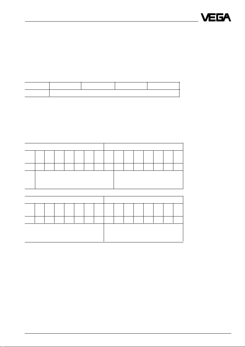
1.9 Data format of the output signal
Byte4 Byte3 Byte2 Byte1 Byte0
Status Meas. value (IEEE-754 format, see below)
Status byte:
The status byte corresponds to the profile 3.0 "Profibus PA Profile for Process Control Devices" coded. The status "Meas. value OK" is coded as 80 (hex) (Bit7 = 1, Bit 6 … 0 = 0).
Measured value:
The meas. value is transferred as 32 Bit floating point number in the IEEE-754 format.
Byte n Byte n+1
Bit Bit Bit Bit Bit Bit Bit Bit Bit Bit Bit Bit Bit Bit Bit Bit
7654321076543210
VZ 27262524232221202-12-22-32-42-52-62
Sign
Exponent Mantissa
-7
Byte n+2 Byte n+3
Bit Bit Bit Bit Bit Bit Bit Bit Bit Bit Bit Bit Bit Bit Bit Bit
7654321076543210
2-82-92
-102-112-122-132-142-152-162-172-182-192-202-212-222-23
Mantissa Mantissa
Formula: Meas. value = (-1)VZ • 2
Examples: 41 70 00 00 (hex) = 0100 0001 0111 0000 0000 0000 0000 0000 (bin)
Meas. value = (-1)0 • 2
(Exponent - 127)
(130 - 127)
• (1 + 2-1 + 2-2 + 2-3)
• (1 + Mantissa)
= 1 • 23 • (1 + 0.5 + 0.25 + 0.125)
= 1 • 8 • 1.875
= 15.0
VEGAFLEX 51P and 52P 17
Page 18

1.10 Dimensions
VEGAFLEX 51
Plastic housing Aluminium housing
201
10˚
101
215
185
Product description
25 116
322
182
165
Cable ø 4 mm uncoated 125 mm
Cable ø 4 mm coated 250 mm
SW 55
G 1½ A
244
90
25
70
ø 4
L
155
ø 8
8
ø 20
370
205
EXD connection housing
268
SW 55
G 1½ A
L
ø 8
Adjustment module MINICOM Cable loops
Tank 1
m (d)
12.345
-
ESC
+
OK
32,5
25
70
ø 4
155
8
ø 20
67,5
74
Adjustment module to be plugged into the
series 50 sensors or into the external indicating instrument VEGADIS 50
Cable - steel
18 VEGAFLEX 51P and 52P
Cable - plastic
coated
Page 19

Product description
VEGAFLEX 52
Plastic housing Aluminium housing
201
215
185
10˚
322
182
165
345
L
SW 64
G 1½ A
101
370
90
25
80
ø 8
205
EXD
connection
housing
25 116
368
SW 64
G 1½ A
L
25
80
ø 8
250
Cable ø 8 mm uncoated 200 mm
Cable ø 8 mm coated 400 mm
ø 12
ø 40
15
ø 12
15
ø 40
VEGAFLEX 51P and 52P 19
250
Page 20

2 Mounting
Mounting
2.1 Installation instructions
Lateral load
Make sure that the measuring cable is not
subjected to strong lateral forces. Mount
VEGAFLEX to a position in the vessel where
no interfering influences from e.g. stirrers,
filling openings etc., can occur.
Lateral load
Extraction forces
In case of strong extraction forces, e.g. during quick emptying or settling of solids, high
tensile loads can occur.
When such an installation position is necessary, the cable should not be anchored but
only equipped with a gravity weight, so that
the cable can more easily follow the product
movements.
Shortening the measuring cable
The cable can be shortened later as required. Loosen the three set screws on the
gravity weight (hexagon) and remove them.
Pull the cable out of the gravity weight.
To avoid fraying the steel cable during cutting, you have to tin the cable around the
cutting position with a soldering iron or torch,
or wrap the cable tightly with wire or insulating tape. Shorten the cable with a metal cutting saw or a cutting wheel to the desired
length.
In case of insulated cables with gravity
weight, a certain length of insulation should
be removed (VEGAFLEX 51: 45 mm; VEGAFLEX 52: 60 mm). In cable loops, the
insulation must remain on the cable.
After shortening, reinsert the cable (see "4.2
Adjustment with adjustment module MINICOM").
L
Make sure that the vessel top can support
the max. tensile load.
Pressure
In case of gauge or low pressure in the vessel, the mounting boss should be sealed on
the thread. Use the attached seal ring. Check
if the seal ring is resistant against the contained medium.
20 VEGAFLEX 51P and 52P
Shortening the measuring cable
Page 21

Mounting
Cable entries
When mounting outdoors, on cooled vessels
or in humid areas where cleaning is done e.g.
with steam or high pressure, the seal of the
cable entry is very important.
Use cable with a round conducting crosssection and tighten the cable entry. The cable
entry is suitable for cable diameters of 5 mm
to 9 mm.
Moisture from outside
To avoid moisture ingress, the electrical connection cable should be looped downward
behind the cable entry so that rain and condensation water can drain off.
This is mainly valid for mounting outdoors, in
areas where humidity is expected (e.g. by
cleaning processes) or on cooled or heated
vessels.
If this happens, anchor the cable. When
straining the cable, avoid high cable tension.
In our price list, you will find a spring (as
accessory) which prevents overloading of
the cable.
Please note that in solids, strained cables
must be able to resist strong forces. In case
of strong extracting forces, the cable should
not be anchored. Please note the paragraph
"Extracting forces".
Cable electrode in solids
Buildup
Generally, buildup on the cable will cause
only slight changes of the measured value. If
strong buildup on the cable is expected, the
use of insulated cable is recommended. The
higher surface quality prevents buildup.
Abrasion
In very abrasive products, e.g. in loose
Moisture
Anchoring
In general, the measuring result will be noticeably influenced if the gravity weight
comes into contact with the vessel wall. Depending on the kind of solid, the installation or
the kind of filling, the cable can "float" in spite
of the gravity weight. The solid can push the
chippings, use a measuring cable without
insulation.
Socket
Sockets cause strong interfering reflections.
Therefore avoid socket mounting. If this is not
possible, choose the flattest socket possible
and use a socket with a diameter of at least
600 mm.
cable to the vessel wall or to the top, causing
incorrect measured values.
VEGAFLEX 51P and 52P 21
Page 22

Mounting
Material cone
When selecting a mounting location for
VEGAFLEX in the vessel, please remember
that material cones can form in solids, causing inaccurate measuring results. We recommend selecting a mounting location where the
cable detects an average value of the material cone.
d
6
d
d
6
VEGAFLEX should be installed at a spot that
takes the filling and emptying apertures of
the vessel into consideration. To compensate
measuring errors caused by the material
cone, you should install the cable at a distance of d/6 from the vessel wall or vessel
installation. In any case keep, a min. distance
of 300 mm.
d
3
10
d
d
1 Emptying
2 Filling opening
3 VEGAFLEX
22 VEGAFLEX 51P and 52P
1
2
Page 23

Electrical connection
3 Electrical connection
3.1 Connection – Connection cable
– Screening
Safety information – Qualified personnel
Instruments which are not operated with
protective low voltage or DC voltage must be
connected only by qualified personnel. This
also applies to the configuration of measuring
systems planned for Ex environment.
As a rule, do all connecting work in the complete absence of line voltage. Always switch
off the power supply before you carry out
connecting work on the sensors. Protect
yourself and the instruments.
Connection cables and bus configuration
Very often "Electromagnetic pollution" by
electronic actuators, energy lines and emitting systems is so considerable that the twowire cable should be screened.
We recommend the use of screened cable.
This screening also guards against future
sources of interference. The screening
should be applied only to one sensor end
(fig. 3.1 a).
It is better if the screens are earthed on both
ends. However, it must be certain that no
earth compensation currents flow via the
sensor cable screens (fig. 3.1 b). Earth compensation currents can be avoided by connecting the cable screen (in case of earthing
on both sides) on one earthed side (e.g. in
the switching cabinet) via a capacitor (e.g.
0.1 µF; 250 V AC) to earth potential. Use a
very low impedance earth connection (foundation, plate or mains earth). In dust-Ex applications the screen should be on one end.
Potential losses can be caused by earthing
on both ends.
Note the Profibus specification. The connection cables must be specified for the expected operating temperatures in the plant
and must have an outer diameter of
6 … 12 mm, to ensure the seal effect of the
cable entry on the sensor.
For power supply and bus communication, a
two-wire cable acc. to the Profibus specification (up to max. 2.5 mm2 cross-section area
of conductor) is used. The electrical connection on the sensor is made by spring-loaded
terminals.
In a laboratory setup, a Profibus system will
also work with standard, unshielded two-wire
cable. In practice however, an automation
network and bus system can only be protected reliably against electromagnetic interference with screened cable. Acc. to the
Profibus specification (IEC 1158-2),
screened and twisted cables are prescribed.
All participants are connected in one line
(serially). At the beginning and end of the
bus segment, the bus is terminated by an
active bus termination. On the DP bus level,
most participants already have a bus termination implemented. With more than 32 participants on the DP level, a so-called repeater
must be used to open and combine another
DP level with a max. of 32 additional participants. On the PA bus branch of the segment
coupler, the PA radar sensors work also with
max. 32 participants (Ex max. 10 participants).
A PA sensor can work only in conjunction with
a Profibus DP system, to which a Profibus PA
subsystem is connected. A PA Profibus participant must consume min. 10 mA supply
current.
VEGAFLEX 51P and 52P 23
Page 24

Electrical connection
Earthing on one sensor end
Processing
Earthing on both ends (on the processing unit via potential separating capacitor)
Fig. 3.1 a
³ 0.1 µF
250 V AC
Processing
In dust-Ex applications the screening should
only be made on one side. Due to potential
difference earthing on both sides is not al-
Fig. 3.1 b
lowed.
24 VEGAFLEX 51P and 52P
Page 25

Electrical connection
Connection cable and cable length
Connection cables must correspond to the
Profibus specification and the FISCO model.
The sensor cable must be in conformity with
the values of the reference cable acc. to
IEC 1158-2:
0.8 mm2; R
Z
= 80 … 120 W; damping = 3 dB/km;
31.25kHz
C
asymmetric
The max. cable length first of all depends on
the transmission speed:
up to 32 kbit/s: 1900 m Profibus PA
up to
94 kbit/s: 1200 m Profibus DP
up to
188 kbit/s: 1000 m Profibus DP
up to
500 kbit/s: 500 m Profibus DP
up to
1500 kbit/s: 200 m Profibus DP
up to
12000 kbit/s: 100 m Profibus DP
The distributed resistance of the cable, in
conjunction with the output voltage of the
segment coupler and the current requirement
(VEGAFLEX 10 mA) or the voltage requirement (VEGAFLEX 9 V) of the sensors, determines the max. length of the cable.
In a practical application of a PA bus branch,
the max. length of the cable is also determined (beside the required supply voltage
and max. current consumption of all participants on the PA bus branch) by the bus
structure and the type of segment coupler
used.
= 44 W/km;
DCmax.
= 2 nF/km.
Ground terminal
The electronics housings of the sensors have
a protective insulation. The ground terminal in
the electronics is galvanically connected with
the metallic process connection. For sensors
with a plastic thread as process fitting, the
sensor grounding must be made by a
ground connection to the outer ground terminal.
Screening
According to the Profibus specification
screening should be applied to both ends. To
avoid potential equalisation currents, a potential equalisation system must be available
in addition to the screening.
According to specification, we recommend
the use of twisted and screened two-wire
cable, e.g.: SINEC 6XV1 830-5AH10 (Siemens), SINEC L26XV1 830-35H10 (Siemens),
3079A (Belden).
Alternatively, when grounding at both ends in
non-Ex areas, the cable shielding can be
connected on one ground side (in the switching cabinet) via a capacitor (e.g. 0.1 µF;
250 V) to the ground potential. Make sure
that the ground connection has the lowest
possible resistance (foundation, plate or
mains earth).
The cable length results from the sum of all
cable sections and the length of all stubs.
Profibus P A in Ex environment
The length of the individual stubs must not
exceed the following lengths:
1 … 12 stubs 120 m (Ex: 30 m)
13 … 18 stubs 60 m (Ex: 30 m)
19 … 24 stubs 30 m (Ex: 30 m)
When used in Ex area, a PA bus with all connected instruments must be carried out in
intrinsically safe protection class "i". Four-wire
instruments requiring separate supply must
at least have an intrinsically safe PA connec-
More than 24 stubs are not permitted,
whereby each branch longer than 1.2 m is
tion. VEGA sensors for PA-Ex environment
are generally "ia” two-wire instruments.
counted as a stub. The total length of the
cable must not exceed 1900 m (in Ex version
1000 m).
VEGAFLEX 51P and 52P 25
Page 26

Electrical connection
In the so-called Fieldbus Intrinsically Safe
Concept (FISCO), the general conditions for
an Ex safe bus configuration have been laid
down. Therein the participants and the bus
cables with their electrical data have been
determined, so that the linking of these components always meets the Ex requirements.
A more time-consuming Ex calculation is
therefore not necessary. You can build your
Ex bus according to the IEC standard 1158-
2.
The Ex segment coupler delivers a controlled
power supply to the PA bus. All other components (field instruments and bus terminators)
are only consumers. A field instrument must
consume at least 10 mA. Ideally, an individual
sensor should not consume more than
10 mA, so that the number of instruments can
be as large as possible.
VEGA PA sensors, whether Ex or non Ex,
consume a constant current of 10 mA. According to the Profibus specification, this is
the minimum participant current. With VEGA
sensors it is therefore possible to connect 10
sensors (also in Ex environment) even with a
limited energy supply from the Ex segment
couplers.
Watch out for potential losses
Due to potential losses, earthing on both
sides without a potential equalisation system
is not allowed in Ex applications. If an instrument is used in hazardous areas, the required regulations, conformity and type
approval certificates for systems in Ex areas
must be noted (e.g. DIN 0165). Please also
note the approval documents with the safety
data sheet attached to the Ex sensors.
Ex protection
If an instrument is used in hazardous areas,
the required regulations as well as the dustEx certificates of VEGAFLEX for systems in
dust-Ex areas must be noted.
Electrical data of the cables
R
DC
No. of A in Z
cores mm
2
31.25kHz
C in Damping Screen
nF/km
SINEC 6XV1 44 W/km 2 0.75 100 W < 90 < 3 dB/km Cu braiding
830-5AH10 +/- 20 W 39 kHz
(Siemens)
SINEC L26XV1 44 W/km 2 0.75 100 W < 90 < 3 dB/km Cu braiding
830-35H10 +/- 20 W 39 kHz
(Siemens)
3079A 105 W/km 2 0.32 150 W 29.5 < 3 dB/km Foil
(Belden) 39 kHz
26 VEGAFLEX 51P and 52P
Page 27
Electrical connection
1
2
4
8
16
32
64
128
8765 4
3
2
1
3.2 Sensor address
In a Profibus system composed of Profibus
DP and Profibus PA subsystem, each participant must have a unique address. Each
participant, whether master or slave, is
accessed by means of its own address in
the bus system. The address of a participant, whether on DP or PA level, should be
assigned before connecting to the bus, because an address can be used only once. If
an address is used twice, interference in the
bus will be caused.
The address of a VEGAFLEX sensor can be
set in three ways:
- with the adjustment software VVO (soft-
ware addressing),
- with the DIP switch block in the sensor
(hardware addressing) or
- with the adjustment module MINICOM.
VEGA Profibus sensors are dispatched with
the address set at 126 (all DIP switches to
"ON").
Remember, in a Profibus system there are
max. 126 participants possible. When the
DIP switch is set to address 126 (or higher),
the address can be adjusted with the adjustment software VVO, the adjustment module
MINICOM or another configuration tool (e.g.
PDM). However, there can be only one sensor on the bus with address 126 (delivery
status) during address assignment via software. For that reason, hardware addressing
(DIP switch) before connection to the bus is
recommended.
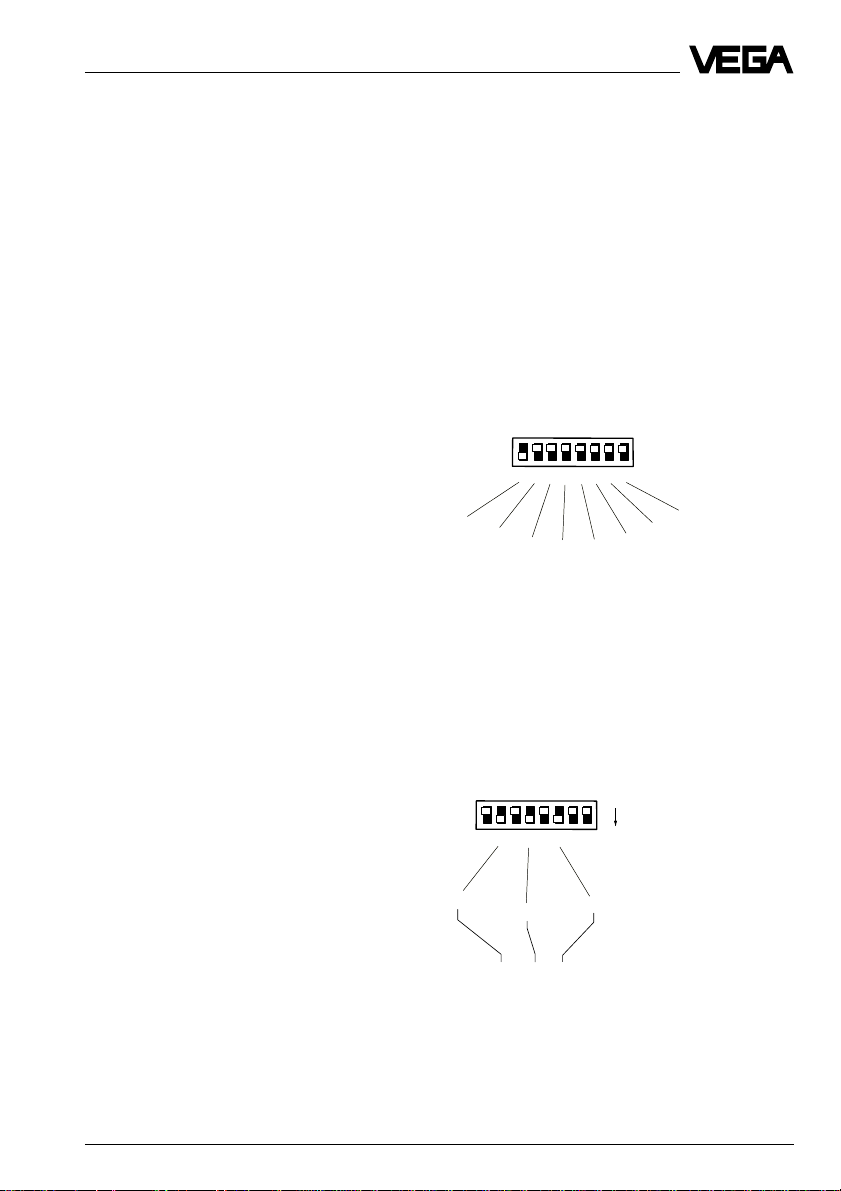
Hardware addressing
The DIP switches generate an address
number in the binary system. This means
that, from right to left (ascending), any switch
represents a number twice as high as the
previous switch on the right. The corresponding number in the decimal system
results from the sum of all switches set to
"ON". In the illustration, you see the decimal
number that corresponds to each individual
DIP switch.
DIP switch 8 corresponds to the number 128,
switch 1 corresponds to the number 1 and
switch 3 corresponds to the decimal number
4.
Example 1
The switches 3, 5 and 7 are set to "ON". The
address is then:
DIP switch 3 to "ON" means 4
DIP switch 5 to "ON" means 16
DIP switch 7 to "ON" means 64
4 + 16 + 64 = Address 84
ON
1
2
8765 4
3
64
VEGAFLEX 51P and 52P 27
16
64 + 16 + 4 = 84
4
Page 28
Electrical connection
Example 2
You want to set address 27.
16 + 8 + 2 + 1 = 27
You must set the DIP switches
5 = 16
4 = 8
2 = 2
1 = 1
to "ON".
Example 3
You want to set address 99
64 + 32 + 2 + 1 = 99
You must set the DIP switches
7 = 64
6 = 32
2 = 2
1 = 1
to "ON".
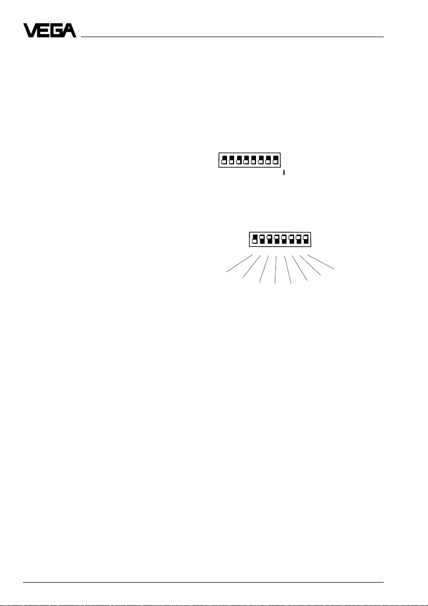
Software addressing
The DIP switches must be set to an address
of 126 … 255, i.e.
- either all DIP switches are set to "ON",
corresponding to address 255 (delivery
status)
OFF
1
2
64
3
ON
8765 4
32
16
1
2
3
1
2
4
8
8765 4
Addr.
- or only DIP switch 8 is set to "ON", corresponding to address 128.
128
Of course, software addressing is also possible if the switches 7 … 2 are set to "ON"
(address 126).
The adjustment of the address with software
VVO is described in the operating instructions of the adjustment software VVO.
It is also possible to set the address with the
adjustment module MINICOM. Please check
the menu schematic of MINICOM.
28 VEGAFLEX 51P and 52P
Page 29

Electrical connection
3.3 Connection of the sensor
• Loosen the closing screw on the upper
side of the sensor.
• Open the sensor cover.
• Remove the compression nut from the
cable entry and slide the nut a small distance over the connection cable.
• Remove the rubber seal from the cable
entry and slide it over the connection cable.
• Strip off the insulation of the connection
cable over a length of approx. 10 cm.
Version with Aluminium housing
Power supply and Profibus signal
+
To the indicating instrument in the
sensor lid or to the external
indicating instrument VEGADIS 50
–
M20x1.5 (diameter of the
connection cable
6…9 mm)
• Insert the cable through the cable entry
into the sensor.
• Connect the cables.
Push back the white tabs of the spring
terminals with a small screwdriver and
insert the copper core of the connection
line into the terminal opening.
Check the hold of the cables in the terminal
by slightly pulling on them.
• Screw the compression nut back on to the
cable entry and fasten it tightly.
Version with plastic housing
Power supply and
Profibus signal
M20x1.5 (diameter of the
connection cable
6…9 mm)
+
To the indicating instrument in the sensor lid or to
the external indicating
–
instrument
Spring-loaded terminals
(max. 2.5 mm2 wire
cross-section)
1
2
3
87654
1
2
3
8 765 4
+1 2- 5678
Addr.
Bus
Display
ON
ESC
-
+
OK
Opening tabs
Pluggable
adjustment
module
MINICOM
+1 2- 5678
Addr.
Bus
Tank 1
m (d)
12.345
Display
ON
ESC
+
-
OK
VEGAFLEX 51P and 52P 29
Page 30

3.4 Connection of the external indicating instrument
Loosen the four screws of the housing lid on
VEGADIS 50.
The connection procedure can be facilitated
by fixing the housing cover during connection work with one or two screws on the right
of the housing.
Adjustment
module
OUTPUT
(to the sensor)
3
2
1
4
5
8
6
7
VEGADIS 50
+
-
Tank 1
m (d)
12.345
Electrical connection
ESC
OK
Voltage supply and
digital meas. signal
-
+
8 7654
+1 2- 5678
Addr.
Bus
Tank 1
m (d)
12.345
DISPLAY
(in the lid of the
indicating
instrument)
1
2
3
Display
ON
ESC
+
-
OK
Screws
30 VEGAFLEX 51P and 52P
Page 31

Setup
4 Setup
4.1 Adjustment media
All VEGA Profibus sensors operate in profile
3 and can be adjusted with:
- the adjustment program VVO on a PC with
Profibus card
- the adjustment program PACTwareTM, under
which VVO runs as a subprogram
- the Siemens software PDM in conjunction
with an EDD (Electronic-Device-Description)
- the adjustment module MINICOM in the
sensor.
Adjustment with VVO on the PC
The adjustment program VVO enables userfriendly adjustment of VEGA Profibus PA
sensors. All functions and options of sensor
adjustment are accessible. The program
runs under Windows® on a PC with a Profibus-Master-Class 2 interface card on Profibus DP level as Master-Class 2 tool. The
VVO program accesses the VEGA PA sensors via the DP bus, the segment coupler
and the PA bus.
The adjustment program VVO from VEGA
makes full range of functions of VEGA sensors available and can update the entire
sensor software if necessary. For this reason,
the adjustment program must be installed on
a PC which is equipped with a ProfibusMaster-Class 2 interface card (Softing) (see
figure on the next page).
The adjustment and parameter data can be
saved with the adjustment software on the
PC and protected by passwords. On request, the adjustment can be also transferred to other sensors.
In practice, the adjustment program VVO is
often installed as a tool on an engineering
station or an adjustment station. VVO then
accesses over the bus each VEGA sensor
via the Profibus interface card (e.g. from
Softing) as Master-Class 2, from the DP level,
through the segment coupler on the PA level
right down to the individual sensor
Device description (DD)
Beside the instrument master file (GSD), by
which a sensor is logged on the Profibus
system, the majority of all Profibus sensors
requires for adjustment, beside the specific
adjustment software, also a so-called EDD
(Electronic Device Description) for each
sensor, to access and adjust the sensor from
the bus levels. This is not the case with VVO.
The adjustment software VVO can communicate at any time with all VEGA sensors without requiring a special database. Of course,
all other VEGA sensors can be adjusted with
the adjustment software as well (4 … 20 mA
sensors or VBUS sensors). With VEGA sensors, it is not necessary to go looking for the
latest EDD. This is the essential requirement
of a manufacturer-independent adjustment
program anticipated by many users.
The PC with the Profibus interface card can
be connected directly at any location on the
DP bus by means of the standard RS 485Profibus cable.
VEGAFLEX 51P and 52P 31
Page 32

Setup
Adjustment with P ACT ware
TM 1)
The adjustment with PACTwareTM corresponds to VVO adjustment, in this case, VVO
runs as a subprogram of PACTwareTM. The
adjustment instructions can be found in the
documentation of PACTwareTM.
Adjustment with PDM
The sensors can be adjusted completely with
PDM. However, some user-friendly functions
and many special features, like e.g. display
of an echo curve, are not available. In addition to the PDM software, an EDD (upon
request available from VEGA) is required for
each sensor type. The adjustment instructions for PDM are described in the PDM
documentation.
Adjustment with the adjustment module
MINICOM
With the adjustment module MINICOM, you
adjust the individual sensor directly on the
sensor or in the external indicating instrument
VEGADIS 50. The adjustment module MINICOM enables (with the 6 key adjustment field
with text display) all essential functions of
parameter setting and adjustment.
4.2 Adjustment with the adjustment
module MINICOM
As with the PC, the sensor can also be adjusted with the small detachable adjustment
module MINICOM. The adjustment module is
inserted into the sensor or into the external
indicating instrument (optional).
ESC
+
Tank 1
-
m (d)
12.345
OK
2
4 ... 20 mA
ESC
+
Tank 1
-
m (d)
12.345
OK
4
The adjustment module also provides all the
adjustment options available on the PC with
adjustment program VVO. All adjustment
steps can be carried out with 6 keys of the
adjustment module. A small display gives
you, beside the measured value, a short
information on the menu item or the value of a
menu adjustment.
Not possible, however, are parts of the adjustment relating to the configuration and
signal processing (e.g. linearisation curve).
This is only possible with the PC.
32 VEGAFLEX 51P and 52P
Page 33

Setup
Adjustment elements
The adjustment module MINICOM is menu
orientated. The clear text indications on the
display lead through the menu. The functions
of the keys are described in the following.
2
1
Tank 1
-
m (d)
12.345
5
OK key (4)
With the OK key adjustments can be confirmed.
When the symbol ▼ or is displayed, you can
move with the OK key to the next lower menu
level.
With the symbol there is no branch below
▼
▼
the menu item but only another menu item of
respective function.
ESC key (3)
With the Escape key (ESC) you can, depending on the menu item, interrupt an adjustment or a function or change to the next
higher menu level.
3
ESC
+
OK
4
▼
▼
Arrow keys (5)
With the keys > and < you can move within
the menu level from one menu item to the
other.
Digital indication (1)
On the digital indication the actual measured
value is displayed during operation. When
you adjust the instrument, the clear text indication displays the appropriate function.
▼
Branching point from which you can
change to a lower menu.
▼
This symbol informs you about an ensu-
▼
ing safety enquiry.
E.g. to reach the top menu level, push the
ESC key several times.
+ and - key (2)
With the keys + and - you can modify the
values of the parameters or choose from
several possibilities.
After pushing the first time, the value to be
adjusted flashes. The value will be modified
by further pushing the key.
VEGAFLEX 51P and 52P 33
Page 34

Setup
Address
First choose a free bus address (see chapter 3.2 Sensor address").
Adjustment steps
On the following pages you see the menu
schematic of the adjustment module MINICOM.
Set up the sensor in the following sequence.
The numbers are stated near the appropriate
menu items in the menu schematic on the
following pages.
1. Adjustment
2. Conditioning
3. Outputs
4. Operating range
5. Meas. conditions
6. Indication of the useful and noise level
1. Adjustment
Under the menu item "
the sensor with which span it should work.
Max.
Min.
Adjustment
100 % (distance to the medium
0.300 m) corresponds to
1200 l
0 % (distance to the medium
5.850 m) corresponds to 456 l
" you inform
Span
Adjustment without medium
• Enter with the "+" and "–" key the distance
to the medium your sensor has at 0 %
filling (example: 5.850 m)
If you do not know the distance, you have
to do a sounding.
• Enter the distance to the medium which
your sensor has at 100 % filling.
Key Display
Sensor
m(d)
4.700
Para-
OK
OK
OK
OK
meter
adjustment
Adjustment
without
medium
Adjustment
in
(min. adjustment)
m(d)
0.0 %
at
m (d)
XX.XXX
1)
Adjustment with medium
Fill the vessel e.g. to 10 %, enter in the menu
"
Min. adjustment
" with the "+" and "–" keys 10
% and confirm with the "OK" key. Then fill the
vessel e.g. 80 % or 100 %, enter in the menu
"
Max. adjustment
" with the "+" and "–" keys 80
% or 100 % and confirm with the "OK" key.
with
medium
You can carry out the adjustment without
medium. Generally, you will carry out the
adjustment without medium, since you can
adjust without filling the vessel.
1)
In case of two values which can be modified, you
can move with the "OK" key to the second value.
34 VEGAFLEX 51P and 52P
Min.
adjust
at %
XXX.X
Max.
adjust
at %
XXX.X
Page 35

Setup
2. Conditioning
Under the menu item "
choose the distance at 0 % and at 100 %
filling. Then you enter the parameter and the
appropriate unit as well as the decimal point.
• Enter in the menu window "
sponds
" the value of the 0 % filling. This will
be e.g. "80" for 80 l.
• Confirm with "OK".
• With the arrow key you change to the
100 % menu. Enter here the value of your
parameter corresponding to a 100 % filling.
E.g. "1200" for 1200 l.
• Confirm with "OK".
• If necessary, choose a decimal point. Note
that max. 4 digits can be shown.
• In the menu "
rameter (mass, volume, distance…)
• In the menu "
unit (kg, l, ft3, gal, m3 …).
• With the ESC key you change to the next
higher menu level. With the arrow key you
choose the next menu item.
• In the menu
between three standard linearisation
curves.
Preadjusted is a linear dependence between percentage value of the product
distance and the percentage value of the
filling volume.
You can choose between linear, spherical
tank and cylindrical tank. The adjustment of
a user-programmable curve is only possible with the PC and the adjustment program VVO.
• In the menu item
adjust a delay for the signal output.
Conditioning
0 % corre-
prop. to
" you choose the pa-
Unit
" you choose the physical
"Lin. curve"
you can choose
"Integration time"
" you
you can
3. Outputs
4. Operating range
Without special adjustment, the operating
range corresponds to the measuring range.
The measuring range was already adjusted
with the min./max. adjustment. It is usually
better to choose a slightly bigger operating
range (approx. 5 %) than the measuring
range (span).
Example:
Set min./max. adjustment: 0.300 … 5.850 m;
operating range to approx. 0.250 … real
cable length.
If you shorten the cable, you have to redefine
the cable length.
5. Meas. conditions
With these functions you can enter the ambient conditions in the vessel.
(see menu schematic)
6. Useful level and noise level
In the menu
tion on the signal quality of the product echo.
The higher the "
the measurement.
Ampl.: means amplitude of the product echo
S-N: means Signal-Noise (useful level
The higher the S-N value (useful level minus
noise level), the higher the reliability:
> 50 dB Measurement very good
40 … 50 dB Measurement good
20 … 40 dB Measurement satisfactory
15 … 20 dB Measurement sufficient
< 15 dB Measurement bad
"Info"
you get important informa-
S-N
" value, the more reliable
in dB (useful echo)
minus noise level)
Under the menu "
display and determine which parameter the
sensor display should show.
VEGAFLEX 51P and 52P 35
Outputs
" you can scale the
Page 36

Menu schematic of the adjustment module MINICOM
Setup
Sensor
m(d)
4.700
Parameter
Sensor
optimise
Sensor
Tag
Sensor
Meas.
enviro
nment
Operating
range
Begin
m (d)
FLEX51
P
0.50
0.50
When switching on, the sensor type and the
software version are displayed for a few seconds.
Configuration
4.
Cable
length
m (d)
6.00
Meas.
condit
ions
Condit
ion
solid
Sensor
Tag
Sensor
5.
Foaming
prod.
No
Sensor
addr.
(••••/ • •••)
Low DK
product
No
126
Meas.
unit
m (d)
False
echo
memory
Update
Meas.
dist.
m (d)
X.XX
Echo
learn
Now !
OK ?
Learning!
Update
Meas.
dist.
m (d)
X.XX
Update
Now !
OK ?
Learning!
Delete
Delate
Now !
OK ?
Delating!
Adjustment
w.out
medium
Adjustment
in
m(d)
1.
0.0 %
at
m (d)
XX.XXX
100.0%
at
m (d)
XX.XXX
with
medium
Minadjust
at %
XXX.X
Maxadjust
at %
XXX.X
Note:
Set up the sensor in the sequence of the
numbers.
Signal
conditioning
Scaling
0 %
correspond
XXXX
2.
Lin.
curve
Linear
100 %
correspond
XXXX
Integr
ation
time
Decimalpoint
888.8
0 s
Prop.
Unit
to
Masse
kg
36 VEGAFLEX 51P and 52P
Page 37

Setup
With these keys you move in
the menu field to the left, the
right, top and bottom.
ESC
False
echo
memory
Reset
Now !
OK ?
Reset
ing!
Distance
m (d)
4.700
Ampl.:
XXdB
S-N:
XX
weitere
Funkt.
Info
False
echo
dB
memory
Reset
Now !
OK ?
Reset
ing!
Language
English
OK
6.
Ampl.:
Sensor
Tag
Sensor
Sensor
type
FLEX51
P
Serial
number
1094
0213
Softw.
vers.
1.00
Softw.
date
15.09.
1997
Sensor
addr.
(••••/ • •••)
126
Distance
m (d)
4.700
S-N:
XXdB
XX
dB
3.
Outputs
PAoutput
Prop.
to
Distance
Error
mode
last
value
Sensor
displ.
Prop.
to
Distance
VEGAFLEX 51P and 52P 37
Simulation
Simulation
Now!
Simulation
XXX.X
OK?
act.
dist.
%
m
X,XX
Fast
change
Yes
Bolt print figures are sensor or
measured value information and
cannot be modified in this position.
The menu items in white letters
stand for figures which can be
modified with the "+" or "–" key
and saved with the "OK" key.
Page 38

Setup
4.3 Adjustment with the PC
Before you can adjust the sensors with the
adjustment program VVO (VEGA Visual
Operating), they must be integrated into the
Profibus system. First of all address the
sensors and connect them to your PA segment. With the attached GSD file you integrate the sensors into your system.
To adjust VEGA sensors with the adjustment
software VVO, the PC or the adjustment
station on which VVO is installed must be
equipped with a Profibus DP interface card
(e.g. of Messrs. Softing). The PC or the adjustment station communicates then as Master-Class 2 participant on the DP bus with the
VEGA sensors on the PA bus segment.
To connect the PC to the DP bus, a standard
RS 485-DTE interface cable (Data Terminal
Equipment) is required. With the cable you
connect the DP interface card on the bus or
to the segment coupler.
PC BUS
Screen 1 1 Screen
– – 2 2 M24
RxD/TxD-P 3 3 RxD/TxD-P
– – 4 4 CNTR-P
GND 5 5 GND
– – 66VP
– – 7 7 P24
RxD/TxD-N 8 8 RxD/TxD-N
– – 9 9 CNTR-P
Profibus-DP DP bus (in brackets the
interface card PIN number of the P+F
segment couplers)
(40)
(55)
(41)
Segment
coupler
Profibus PA
cable
VVO
DP cable
Profibus DP
interface card
(Messrs. Softing)
Sensor Sensor Sensor Sensor
If the computer is connected to the Profibus
DP cable, you can start VVO.
• Switch on the power supply of the connected sensor.
• Start the adjustment software VVO (VEGA
Visual Operating) on your PC.
• In the entrance window you choose with
the arrow keys or the mouse the item
ning
and click to OK.
You should only choose
Planning
Plan-
if you are
authorised to modify instrument parameters. Otherwise choose
tenance
In the window
.
User identification
Operator
or
Main-
you are
asked for the name and the password.
• For setup (
planning
) enter under name:
VEGA and under password also: VEGA. It
does not matter if you use capital or small
letters.
VVO determines automatically the type of the
connected sensor and shows shortly with
which sensor a connection exists.
Further information on the adjustment with
PC and the adjustment software VVO is
stated in the operating instructions of the
adjustment software VEGA Visual Operating
(VVO).
38 VEGAFLEX 51P and 52P
Page 39
Setup
Configuration
The term "Configuration" means the basic
adjustments of the meas. system. You inform
the meas. system about the application (level
measurement, gauge, distance …), the
measurement loop name and the DCS output
address of the sensors. The configuration
corresponds to an electronic wiring and
labelling of your sensor or, in other words,
telling the system which sensor for what
application and where.
Parameter adjustment
After the configuration, you carry out the
parameter adjustment for each individual
sensor. This means adjusting the sensors to
the respective operating range and adjusting
to the actual application. You inform the sensor which product distance (which level) is
"empty" and which "full". This is called adjustment. Here you choose in which physical unit
(volume, mass) and unit of measurement (m3,
gal, liters …) the adjusted measured value
should be outputted. In the submenu "Sensor
optimisation" you inform the sensor electronics about the actual environment, such as
e.g. quick changes of the measured value,
foam generation, gas stratification, solid or
liquid.
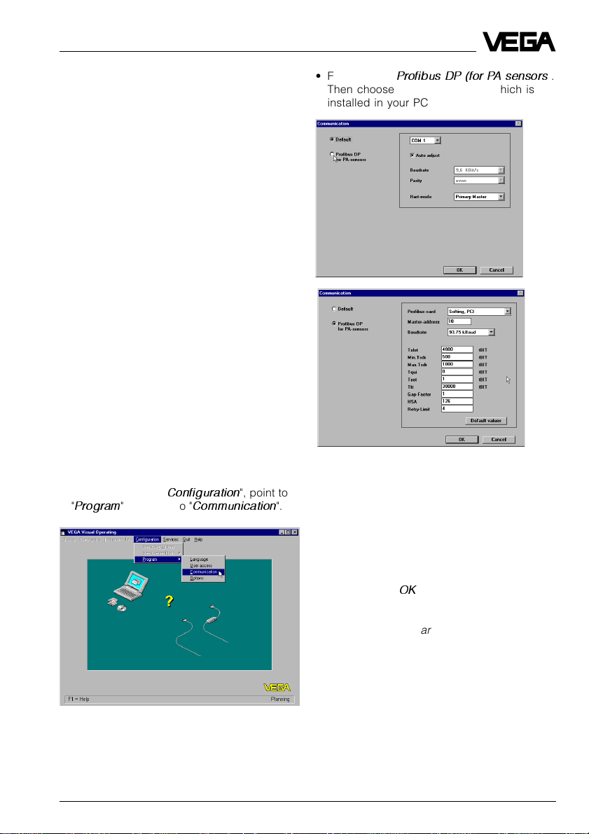
• To do this click to "
"
Program
" and click to "
Configuration
Communication
", point to
".
• First click to "
Profibus DP (for PA sensors
Then choose the Profibus card which is
installed in your PC.
The window for the bus communication adjustments opens. Ten is preadjusted as address for the Master-Class 2 interface card. If
participant number ten is free on your bus,
you can accept the setting. Typical values for
bus parameters have been preset. At this
point, you should adjust the communication
parameters that apply to your system.
).
• Now click to "OK".
The message "
dows® must be restarted
VEGAFLEX 51P and 52P 39
VVO will shut down and Win-
" appears.
Page 40

Note: As a rule, a Windows® restart is not
necessary.
• Now start VVO (restart).
Special functions
As soon as a VEGAFLEX sensor has been
identified, you can choose with the adjustment software VVO some special functions of
VEGAFLEX.
Under the menu item Instrument data/Parameter adjustment you can choose the sensor
optimisation.
Here you find all special functions of VEGAFLEX:
- meas. environment
- echo curve
Measuring environment
Setup
Operating range
With this command you can limit the operating range of the sensor or enter the cable
length again after shortening the cable. Carry
out the adjustment before modifying the operating range, since a later adjustment can
overwrite the values of the operating range.
The right side of the graphics shows the
operating range, the left side the adjustment.
If you, for example, do not want to fill your
vessel completely, you can limit the operating
range.
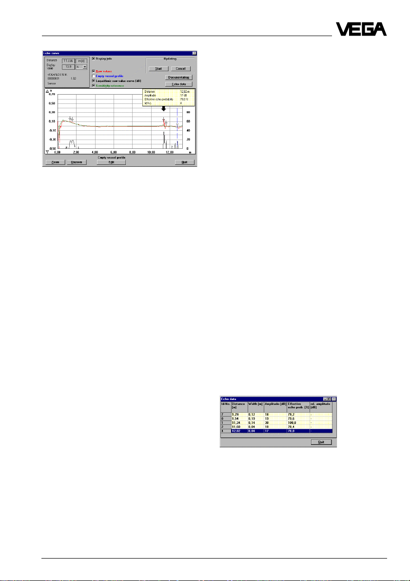
Echo curve
The echo curve shows all reflections of the
guided microwave signal. This means not
only the product signal is shown but also
false signals caused, e.g. by vessel installations.
Measuring conditions
Choose in this menu if you want to measure in
solids or liquids.
If you want to measure a product the DK
value of which is below 2, you can increase
the sensitivity of the sensor.
40 VEGAFLEX 51P and 52P
Generally, the sensor identifies the biggest
amplitude as the useful echo. You see a
black arrow above the highest amplitude.
When you click to "Display info", a small window is displayed, listing the detailed values
of the selected echo.
Page 41
Setup
Empty vessel profile (blue)
This curve shows in normal condition the
actual empty vessel profile.
To gate out of false echoes, you can modify
the blue curve of the vessel profile with the
function "Empty vessel profile".
Reference line (green)
All amplitudes of the red curve which are
below the green reference line are suppressed (ringing, noise, false echoes etc.).
Zoom/Unzoom
After activation of these two functions, you
can either zoom or unzoom the curve with the
left mouse key.
When you activate "Zoom", you can choose
the requested part of the figure by pushing
the left mouse key and drawing a frame.
The following curves can be displayed:
Raw value curve (red)
The red curve means the absolute signal
which the receiver of VEGAFLEX detects.
Beside the useful echo, this curve also contains false signals.
The highest amplitude is detected as useful
echo. Check by sounding to determine if the
value of the useful echo corresponds to the
actual distance to the level.
If the two values do not correspond, you
have to gate out the dominant false echoes
with the function "Empty vessel profile".
All amplitudes above this line are possible
echoes which are processed by the software.
Logarithmic raw value curve (black)
The curve shows the difference between raw
value curve (red) and reference line (green).
The scale on the right side (dB) applies to
this curve.
Documentation
If you click on the button "Documentation", the
actual echo curve will be saved.
Echo data
If you click on the button "Echo data", a window is displayed in which all echoes detected by the sensor are listed with dB
information and a probability evaluation.
VEGAFLEX 51P and 52P 41
Page 42

Start
If you click to "Start", the echo curve will be
updated continuously. With "Stop" you can
terminate the update.
Empty vessel profile
With the functions in this window you can
gate out false echoes. The blue empty vessel
profile curve in the echo curve window shows
the actual empty vessel profile.
Determine the level by sounding. If the sensor has identified a false echo as most probable echo instead of the actual filling level,
you can gate the echo out.
Choose the function "Create new". Enter the
measured distance to the medium. All false
echoes in the range up to the adjusted distance are automatically gated out.
With "Update" you can extend the empty
vessel profile if new false echoes occur as
the level falls. If you want to delete the existing empty vessel profile, click to "Cancel".
Setup
42 VEGAFLEX 51P and 52P
Page 43

Diagnostics
5 Diagnostics
5.1 Simulation
To simulate a certain filling, you can call up
the function "Simulation" on the adjustment
module MINICOM or in the software VVO
program.
You simulate a certain measured value and
thereby a certain sensor current. Please note
that connected instruments, such as e.g. a
PLC, react according to their adjustments
and will probably activate alarms or system
functions.
Simulation with VVO
If you start the simulation mode with the adjustment program VVO on the PC, the simulated level is outputted until you quit the
simulation mode.
Simulation with MINICOM
If you start the simulation mode on the adjustment module MINICOM, the sensor returns
to standard operating mode after one hour.
5.2 Function diagram
The following function diagram is used for
setup with the automation system, if there is
no adjustment software available. Make sure
that all VEGA sensors are profile 3 sensors.
In general, the setup of the sensors can be
carried out very conveniently with the VEGA
adjustment software VVO or with the adjustment module MINICOM in the sensor.
The function diagram is generally not necessary for setup and is used only to deepen
the knowledge of the interested user who is
able to read in the sensor measured values
into the processing system (also without
adjustment tool).
VEGAFLEX 51P and 52P 43
Page 44

Raw-Distance
(value, status)
[in m]
Sensor value (Float)
[sensor unit (m,ft ...)]
Sensor offset (Float)
[sensor unit (m,ft ...)]
Zero adjust
Zero offset
Function diagram and PA parameters
F Time (Float)
(sec)
(not available over
PA Parameter)
Filter
Cal point hi, cal point lo (Float)
[sensor unit (m,ft ...)]
Level hi, level lo (Float)
[level unit (%,m,ft ...)] (*1)
Cal type (Unsigned8)
Live adjustment (min-max) and
dry adjustment possible
Cal
Level hi
Level lo
Cal point hi Cal point lo
Simulate procent value (DS_50)
[level unit (%,m,ft...)] (*1)
(manuf. spec. parameter)
Simulation
off
on
Simulate value
Level (Float)
[level unit (%,m,ft...)] (*1)
Level offset (Float)
[level unit (%,m,ft...)] (*1)
Offset
Offset
44 VEGAFLEX 51P and 52P
Page 45

Function diagram and PA parameters
Simulation distance value (DS_50)
[sensor unit (m,ft ...)]
(manuf. spec. parameter)
Simulation
off
on
Simulate value
Secondary value 2 (DS_33)
[secondary value 2 unit, (m,ft ...)]
distance
Max min memory
max
min
Secondary value 1 (DS_33)
[secondary value 1 unit
(%,m,ft...)] (*1)
Max sensor value,
min sensor value (Float)
[sensor unit (m,ft ...)]
Lin type (Unsigned8),
Tab index (Unsigned8),
Tab X Y value (2 x Float)
[level unit (%,m,ft ...). (*1)
primary value unit (%,m,ft ...)]. (*1)
Tab min number (Unsigned8),
Tab max number (Unsigned8),
Tab op code (Unsigned8),
Tab status (Unsigned8),
Tab actual number (Unsigned8)
Linearization
level %
Transducer
Block
Primary value (DS_33)
[primary value unit (%,m,ft...)] (*1)
lin %
A
B
distance
C
VEGAFLEX 51P and 52P 45
Page 46

lin %
level %
distance
Display source select
(Unsigned8)
Source selector
scale
PV FTime (Float)
[sec]
Function diagram and PA parameters
Sensordisplay
VEGA
Hi hi limit, hi limit,
lo limit, lo lo limit,
alarm hys
(Float) [out scale unit]
Alarm checkFilter
Hi hi limit
Hi limit
Lo limit
Lo lo limit
Alarm hyst
Hi hi alarm, hi alarm,
lo alarm, lo lo alarm
(DS_39)
Alarm sum (DS_42)
lin %
A
B
C
level %
Channel (Unsigned16)
Channel
distance
Simulate Linearization value (DS_50)
[primary value unit (%,m,ft ...).(*1)
secondary value 1 unit, (%,m,ft ...).(*1)
secondary value 2 unit, (m,ft ...)
(dep. on channel)]
Simulation
off
on
Simulate value
46 VEGAFLEX 51P and 52P
Page 47

Function diagram and PA parameters
Fail safe value (Float)
[out scale unit]
Fail safe type (Unsigned8)
Target mode (Unsigned8)
Out (DS_33)
[out scale unit]
Fail safe
Fail safe value
Divice status
PV scale (2 x Float)
[primary value unit (%,m,ft ...).(*1)
secondary value 1 unit, (%,m,ft ...).(*1)
secondary value 2 unit, (m,ft ...)
(dep. on channel)]
PV Scale
1
0
EU 0% EU 100%
Mode
Auto
Man
Mode & Status calc.
Out scale (DS_36)
[out scale unit (included)]
Out Scale
EU 100%
EU 0%
Data value (DS_33)
[out scale unit]
Actual mode
(DS_37)
Function
Block
10
VEGAFLEX 51P and 52P 47
Page 48

5.3 Error rectification
Error Error rectification
Diagnostics
E 013 Sensor cannot find - Message is displayed during the warm-up
E 017 Adjustment span too small Carry out a new adjustment.
E 036 Software update incorrect Return the instrument for repair.
E 040 Hardware failure / Check all connection cables.
level echo phase.
- If the message remains, the DK-value
of the medium could be too low.
Check the useful level and noise level.
See 4.2 Adjustment with adjustment module
MINICOM / Useful and noise level (6).
If the message still remains, carry out a
new adjustment.
Make sure that the difference between min.
and max. adjustment is at least 10 mm.
- Sensor requires programming (service).
- Failure message remains also during a
current programming.
electronics defect Contact our service department.
48 VEGAFLEX 51P and 52P
Page 49

Parameters
5.4 PA parameters
The following parameter listing and the function diagram are used for setup with the
automation system, if no adjustment software
is available. The listing represents the parameters of the function block and transducer block and is only meant for very
experienced Profibus users. Make sure that
all VEGA sensors are profile 3 sensors. Normally, you will carry out the setup of the sensors with greater ease using the VEGA
adjustment software VVO or the adjustment
module MINICOM in the sensor.
The PA parameters and the function diagram
are generally not necessary for setup.
VEGAFLEX 51P and 52P 49
Page 50

Index P arameter Object Read Write T ype Size Store Unit
0 Directory object header DM Ja Nein Array of
1 Composite list directory
entries
16 Block object FB_Primary_Value Ja Nein DS-32 20 C m
17 St rev FB_Primary_Valu e Ja Nein Unsigned16 2 N m
18 Tag desc FB_Primary _Value Ja Ja OctetString 32 S m
19 Strategy FB_P rimary_Value Ja Ja Unsigned16 2 S m
20 Alert key FB_Primary_Valu e Ja Ja Unsigned8 1 S m
21 Target mode FB _Primary_Value Ja Ja Unsigned8 1 S m
22 M ode blk FB_Primary_Valu e Ja Nein DS-37 3 D m
23 Alarm sum FB_Primary_Value Ja Nein DS-42 8 D m
24 Batch FB_Primary_Value Ja J a DS-67 10 S m
26 Out FB_Primary_Value Ja Ja (*1) DS-33 5 D [out scale unit] m
27 PV scale FB_Prima r y_V a l ue Ja Ja 2 * Fl oa t 8 S [pri m, sec1, sec2 v a l ue
28 Out scale FB_Primary_Va lue Ja Ja DS-36 1 1S includes out scale unit m
29 Lin type FB_Primary_Value Ja Ja (*1) Unsigned8 1 S m
30 C hannel FB_Primary_Value Ja Ja Unsigned16 2 S m
32 PV FTime FB_Primary_Value Ja Ja Float 4 N sec m
33 Fsafe type FB _Primary_V alue Ja Ja Unsigned8 1 S o
34 Fsafe value FB_Primary_Value Ja Ja Float 4 S [out scale unit] o
35 Alarm hys FB_Primary_Value Ja Ja Float 4 S [out scale unit] m
37 HI HI Lim FB_Primary_Value Ja Ja Float 4 S [out scale unit] m
39 HI Li m FB_Primary_Value Ja Ja Float 4 S [out scale unit] m
41 LO Lim FB _Primary_Value Ja Ja Float 4 S [out scale unit] m
43 LO LO Lim FB_Primary_Value Ja Ja Float 4 S [o ut scale unit] m
46 HI HI Alm FB_Primary_Value Ja Nein DS-39 1 6 D o
47 HI Alm FB_Primary _Value Ja Nein DS-39 16 D o
48 LO Alm FB _Primary_Va lue Ja Nein DS-39 16 D o
49 LO LO Alm FB_Primary_Value Ja Nein DS-39 16 D o
50 Simulate FB_Prima r y_V a l ue Ja Ja DS-5 0 6 N [pr im, sec1, se c2 valu e
61 View object
FB_Primary_Value
DM Ja Nein Array of
FB_Primary_Value Ja Nein OctetString 18 D m
Unsigned16
Unsigned16
12 C m
24 C m
unit (dep. on channel)
unit (dep. on channel)
PA parameters
Optio nal
manda t ory
m
m
50 VEGAFLEX 51P and 52P
Page 51

PA parameters
Index P arameter Object Read Write T ype Size Store Unit
66 Block obj e ct PB Ja Nei n DS- 3 2 20 C m
67 St rev PB Ja Nein Unsigned16 2 N m
68 Tag desc PB Ja Ja OctetString 32 S m
69 St rategy PB Ja Ja Unsigned16 2 S m
70 Alert key PB Ja Ja Unsigned8 1 S m
71 Target mode PB Ja Ja (* 1) Unsigned8 1 S m
72 M ode blk PB Ja Nein DS-37 3 (D) m
73 Alarm sum PB Ja Nein DS-42 8 D m
74 Softw a r e revis i on PB Ja Nein Octe tS tr i ng 16 C m
75 Hardwar e revisi on PB Ja Ne i n Oc te tStrin g 16 C m
76 Device man ID PB Ja Nein Unsigned16 2 C m
77 Devi ce ID PB Ja Nein OctetS tr i n g 16 C m
78 Device ser num PB Ja Nein OctetString 16 C m
79 Diagno sis PB Ja Nein OctetString 4 D m
81 Diagnosis mask P B Ja Nein OctetString 4 C m
83 Device certification PB Ja Nein OctetString 32 C o
84 Write locking PB Ja Ja Unsigned16 2 N o
85Factory reset PB JaJaUnsigned162S o
86 D ecriptor PB Ja Ja Octet String 32 S o
87 Device me ssa g e PB Ja Ja Octe tS tr i n g 32 S o
88 Devi ce i n sta l l d a te PB Ja Ja OctetS tr i n g 1 6 S o
90 Ident number select PB Ja Ja Unsigned8 1 S m
91 HW write protection PB Ja Nein Unsigned8 1 D o
99 VVO PB Ja Ja OctetString 32 o
100 View object PB PB Ja Nein Octe tS tr i n g 1 7 D m
180 Display source select TB Ja Ja Unsigned8 1 N o
120 Block object TB_Level Ja Nein DS-32 20 C m
Optio nal
manda t ory
VEGAFLEX 51P and 52P 51
Page 52

PA-Parameter
Index P arameter Object Read Write T ype Size Store Unit
121 St rev TB_Level Ja Nein Unsigned16 2 N m
122 Tag desc TB_Level Ja Ja OctetString 32 S m
123 St rategy TB_Level Ja Ja Unsigned16 2 S m
124Alert key TB_Level JaJaUnsigned8 1S m
125 Target mode TB _Level Ja Ja (*1) Unsigned8 1 S m
126 M ode blk TB_Level Ja Nein DS-37 3 (D) m
127 Alarm su m T B_L e ve l Ja Nein DS - 42 8 D m
128 Primary value TB_Level Ja Nein DS-33 5 D [primary value unit] m
129 Primary value unit TB _Level Ja Ja Unsigned16 2 S m
130 Level TB_Level Ja Nein Flo at 4 D [level unit] m
131 Level unit TB_Level Ja Ja Unsigned16 2 S m
132 Senso r value TB_Level Ja Nein Float 4 D [sensor unit] m
133 Senso r unit TB_Level Ja Ja Unsigned16 2 S m
134 Seco ndary value 1 TB_Level Ja Nein DS-33 5 D [secondary value 1
135 Seco ndary value 1 unit TB_Level Ja Ja Unsigned16 2 S o
136 Seco ndary value 2 TB_Level Ja Nein DS-33 5 D [secondary value 2
137 Seco ndary value 2 unit TB_Level Ja Ja Unsigned1 6 2 S o
138 Senso r offset TB_Level Ja Ja Float 4 S [sensor unit] m
139 Cal type TB_Level Ja Ja Unsigned8 1 S m
140 Cal po int lo TB_Level Ja Ja Float 4 S [sensor unit] m
141 Cal point hi TB_Level Ja Ja Float 4 S [sensor unit] m
142 Level lo TB _Level Ja Ja Float 4 S [level unit] m
143 Level hi TB _Level Ja Ja Float 4 S [level unit] m
144 Level offset TB _Level Ja Ja Float 4 S [level unit] m
145 Lin type TB _Level Ja Ja Unsigned8 1 S m
148 Senso r high limit TB_Level Ja Nein Flo at 4 C [sensor unit] o
149 Senso r low limit TB_Level Ja Nein Float 4 C [sensor unit] o
150 Max sensor value TB_Level Ja Ja Float 4 N [sensor unit] o
15 1Mi n sensor va l u e TB_Level Ja Ja Float 4 N [se n sor unit] o
156 Tab index TB _Level Ja Ja Unsigned8 1 D o
unit]
unit]
Optio nal
manda t ory
o
o
52 VEGAFLEX 51P and 52P
Page 53

PA-Parameter
Index P arameter Object Read Write T ype Size Store Unit
157 Tab X Y value TB_Level Ja Ja 2 * Float 8 N [secondary value 1 unit,
158 Tab min number TB_Level Ja Nein Unsigned8 1 C o
159 Tab max number TB_Level Ja Nein Unsigned8 1 C o
160 Tab op code TB_Level Ja Ja Unsigned8 1 D o
161 Tab status TB_Level Ja Nein Unsigned8 1 D o
162 Tab actual number TB_Level Ja Nein Unsigned8 1 D o
190 Simulate sensor value TB_Level Ja Ja DS-50 6 N [sensor unit] o
191 Simulate level TB_Level Ja Ja DS-50 6 N [level unit] o
19 2 F üllguttyp TB_Level Ja J a Unsigned8 1 N o
193 Echo quality TB_Level Ja Nein Unsigned8 1 D dB o
194 First echo factor TB _Level Ja Ja Unsigned8 1 N o
196 Lerndistanz TB _Level Ja Ja Float 4 D [sensor unit] o
19 7 S t ö rech o speicher-
Aktion
198 Arbeitsbereich
Ende
199 Arbeitsbereich
Anfang
200 schnelle
Meßwertänderung
201 unruhige
Füllgutoberfläche
202 Schaum bildung TB_Level J a J a Unsigned8 1 N o
203 st ark e
Staubentwicklung
204 Bodenreflexion / großer
Schüttwinkel
205 kleiner DK-Wert TB_Level Ja Ja Unsigned8 1 N o
210 Korrektur-
faktor Au sbr-.geschw.
211 Berechn. Korr.fak.
Ausbr.
212 Rohrdurchmesser TB_Level Ja Ja Float 4 N [sensor unit] o
250 View object TB_Level TB _Level Ja Nein OctetString 22 D m
TB_Level Ja J a Unsigned8 1 D o
TB_Level Ja Ja Float 4 N [sensor unit] o
TB_Level Ja Ja Float 4 N [sensor unit] o
TB_Level Ja J a Unsigned8 1 N o
TB_Level Ja J a Unsigned8 1 N o
TB_Level Ja J a Unsigned8 1 N o
TB_Level Ja J a Unsigned8 1 N o
TB_Level Ja J a Float 4 N % o
TB_Level Nein Ja Float 4 N [sensor unit] o
primary value unit]
Optional
manda to ry
o
VEGAFLEX 51P and 52P 53
Page 54

Notes
54 VEGAFLEX 51P and 52P
Page 55

Notes
VEGAFLEX 51P and 52P 55
Page 56

VEGA Grieshaber KG
Am Hohenstein 113
D-77761 Schiltach
Phone (0 78 36) 50 - 0
Fax (0 78 36) 50 - 201
E-Mail info@de.vega.com
www.vega.com
ISO 9001
All statements concerning scope of delivery, application, practical
use and operating conditions of the sensors and processing systems correspond to the latest information at the time of printing.
Technical data subject to alterations
2.25 321 / October 2000
 Loading...