

Page 1
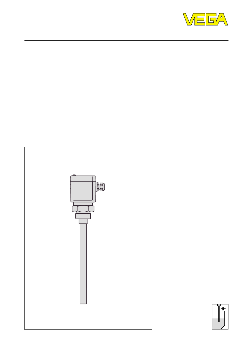
Operating Instructions
VEGACAP
Level and Pressure
Page 2

Safety information
Safety information
Please read this manual carefully, and also take
note of country-specific installation standards
(e.g. the VDE regulations in Germany) as well
as prevailing safety regulations and accident
prevention rules.
For safety and warranty reasons, any internal
work on the instruments, apart from that involved in normal installation and electrical connection, must be carried out only by qualified
VEGA personnel.
2 VEGACAP
Note Ex area
Please note the approval documents (yellow
binder), and especially the included safety
data sheet.
Page 3

Contents
Contents
Safety information ........................................................................ 2
Note Ex area ................................................................................ 2
1 Product description
1.1 Function and configuration .................................................. 4
1.2 Types and versions ............................................................. 6
1.3 Technical data ....................................................................... 7
1.4 Dimensions ......................................................................... 10
1.5 Product temperature and operating pressure ............... 14
1.6 Approvals ........................................................................... 16
2 Mounting
2.1 Mounting instructions ......................................................... 17
3 Electrical connection
3.1 Connection instructions ..................................................... 21
3.2 Connection plan ................................................................. 21
4 Setup
4.1 Adjustment elements ......................................................... 24
4.2 Switching point adjustment ............................................... 25
4.3 Functions chart ................................................................... 29
5 Diagnostics
5.1 Simulation ............................................................................ 30
5.2 Maintenance ....................................................................... 30
5.3 Repair .................................................................................. 30
5.4 Exchange of electronics .................................................... 31
5.5 Shortening of the electrodes ............................................. 31
5.6 Failure rectification ............................................................. 33
VEGACAP 3
Page 4
1 Product description
Product description
1.1 Function and configuration
The compact capacitive level switches VEGACAP detect the level of virtually any medium regardless of whether in liquid, powder,
paste or granule form. This applies also to
adhesive products.
Depending on the chosen adjustment,
VEGACAP can detect if the medium exceeds
or fails to reach a defined level.
Sensor, processing electronics and power
supply form one unit in VEGACAP. The
modular construction ensures adaption to
virtually any application. Beside rod, cable,
high temperature and plate electrodes, there
are also three electronics versions available
(non-contact switch, relay or transistor output
NPN/PNP).
VEGACAP 27, 35 and 98 combine all these
positive features with the advantage that an
adjustment with medium is no longer necessary. This is made possible by the oscillator
CAP E31 R and the patented mechanical
configuration of the electrode.
Application
The area of application for VEGACAP is
mainly in the detection of max. and min. levels
in vessels. A switching command can be
triggered either when the electrode is immersed or exposed. VEGACAP can be
mounted laterally, from the top or from the
bottom.
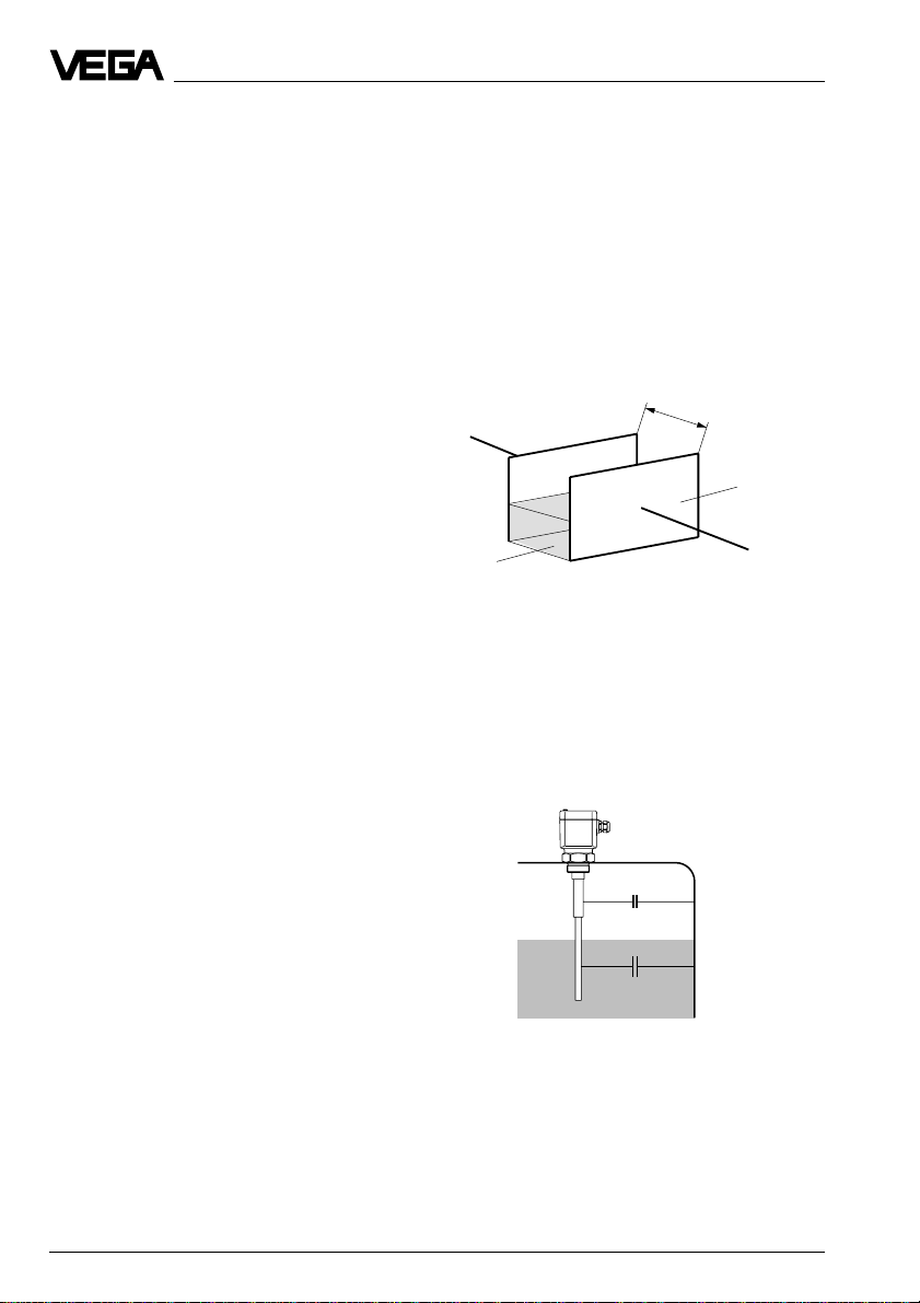
Measuring principle
Electrode, medium and vessel wall form an
electrical capacitor.
The capacitance of the capacitor is generally
influenced by three factors:
- distance of the electrode plates (a)
- size of the electrode plates (b)
- type of dielectric between the electrodes
(c)
a
b
c
The electrode and the vessel wall are the
capacitor plates. The medium is the dielectric. Due to the higher dielectric constant (DKvalue) of the medium compared with air, the
capacitance of the capacitor increases as the
electrode is gradually immersed.
Partly insulated
The electrode is insulated over a defined
length. The measurement is made only in the
uninsulated zone.
Fully insulated
The electrode is insulated along the entire
The capacitance change is converted by the
oscillator into a switching command.
length; on cable electrodes also the gravity
weight can be fully insulated.
4 VEGACAP
Page 5

Product description
Buildup resistant
(VEGACAP 26, 27, 35 and 98)
The special mechanical construction compensates conductive buildup. Leakage currents caused by build-up are drained off via
the screen segment.
Even strong condensation or buildup do not
influence the switching condition of VEGACAP.
The compensation of buildup is supported
by the patented processing technology
(phase selective admittance processing) in
the oscillator CAP E31 R.
VEGACAP 35 can be shortened locally to the
requested length. Planning and stocking is
thereby facilitated.
Adjustment-free
(VEGACAP 27, 35 and 98)
Set-up is very easy because the switching
point must no longer be adjusted.
Adjustment-free means that changing mediums with different dielectric constant figures
(er), e.g. water and oil or conductive and nonconductive mediums, do not influence the
adjustments on VEGACAP and the switching
accuracy.
With horizontally installed electrodes, the
installation position is also the position of the
switching point.
Note
Check for correct functioning of the sensor.
When filling for the first time, make sure that
VEGACAP responds and switches correctly
so that in case of failure, the filling or emptying process can be manually stopped.
With vertical installation, the switching point is
only determined by the length of the electrode.
All products with a dielectric constant ³ 1.5
can be detected. With a DK value < 2 a fresh
adjustment must be carried out on VEGACAP
27 and 98.
VEGACAP 5
Page 6
Product description
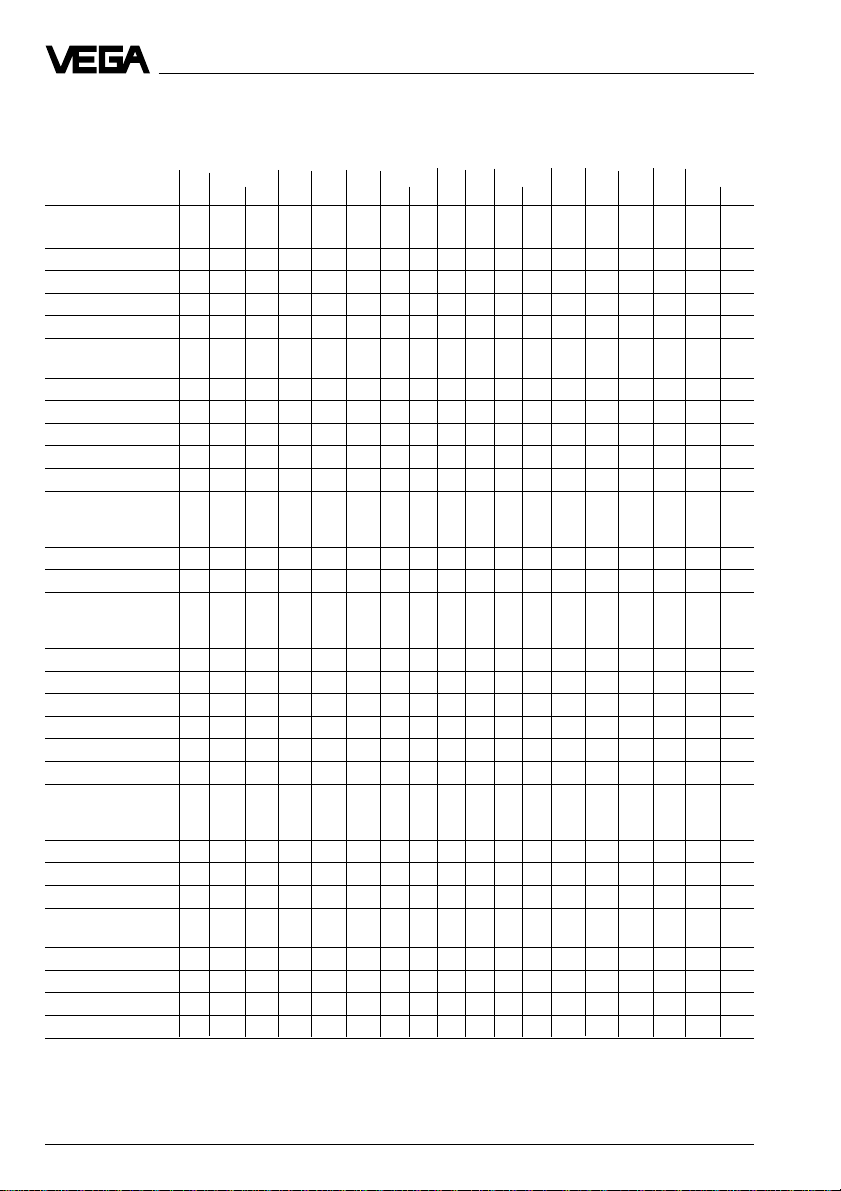
1.2 Types and versions
Type survey
VEGACAP 111)21 26 27 311)33 34 35 42 52 53 60 61 821)84 92 97 98
Series
Rod electrode • • • • • • •
Cable electrode • • ••••• •
Plate electrode ••
Pipe clamp electr. •
Version
Partly insulated • • • • • • • •
Fully insulated • • • • • • • • •
Thread
NPT 11/2" • • • • • • •••••
G 11/2 A • • • • • • ••••••• •
Electrode
material
Steel • • • • • • ••••••• •
StSt • • • • • • • • • • •
Insulating
material
PTFE • • • • • • • • • •
PP • • • •
PE/PA 12 • • •
PFA • • •
PE •
Ceramic • •
Temperature
adapter
Steel • • • • • • •
StSt • • • • • • •
PA •• •• •• • •
Others
Test switch • • • • • • ••••• • • • •
Adhesive prod. • • • • •
Adjustment-free • • •
High temp. version • •
1)
VEGACAP 11 R ExS, 31 R ExS and 82 R ExS with integrated oscillator E30 R ExS are approved for StEx
applications.
6 VEGACAP
Page 7

Product description
1.3 Technical data
General
Housing
Housing material plastic PBT (Polyester)
Protection class plastic IP 66 (StEx IP 65)
Cable entry 1 x Pg 13.5
Terminals for max. 1.5 mm2 wire cross-section
Thread
Material
- VEGACAP all except VEGACAP 97, 98 steel (St 37), 1.4571 (stst), Aluminium
- VEGACAP 97, 98 PP
Thread G 11/2 A or NPT 11/2“
Rod electrode (VEGACAP 11, 21, 26, 27, 60, 97, 98)
Rod material
- VEGACAP 11, 21, 26, 27, 60 steel (St 37) or 1.4571 (StSt)
- VEGACAP 97, 98 PP (insulation)
Length
- VEGACAP 11, 21, 26, 27 max. 4 m
- VEGACAP 97, 98 max. 1.5 m
VEGACAP 27, 35, 98 also Aluminium
Aluminium IP 66/67
(with oscillator R = 2 x Pg 13.5)
also flange or hygienic versions
Cable electrode (VEGACAP 31, 33, 34, 35, 42, 52, 53, 61)
Cable material
- VEGACAP 31, 33, 42, 61 steel (St 37) or 1.4571 (stst)
- VEGACAP 34, 35, 52, 53 steel (St 37)
Length max. 25 m (VEGACAP 35 max. 20 m)
Weight
Basic weight
- VEGACAP 11, 21, 26, 27 approx. 1.2 kg
- 31, 33, 34, 35, 42, 52, 53, 60, 61 approx. 3.3 kg
- VEGACAP 82, 84, 92 approx. 2.1 kg
- VEGACAP 97, 98 approx. 0.6 kg
Rod weight approx. 1.4 kg/m
Cable weight
- all except VEGACAP 42 approx. 0.3 kg/m
- VEGACAP 42 approx. 0.1 kg/m
Ambient conditions
Ambient temperature on the housing -40°C … +70°C
- StEx version -20°C … +60°C
Storage and transport temperature -40°C … +80°C
Medium temperature and operating see "1.5 Medium temperature and operating
pressure pressure“
Dielectric constant er medium ³ 1.5
VEGACAP 7
Page 8

Product description
Function
Modes A/B mode
Integration time approx. 0.5 sec
Signal lamp LED for indication of the switching mode
Test switch (option) switching point simulation
CE conformity
VEGACAP compact level switches meet the protective regulations of EMC (89/336/EWG)
and NSR (73/23/EWG). The conformity has been judged acc. to the following standards:
EMC Emission EN 50 081 - 1: 1992
Susceptibility EN 50 082 - 1: 1992
NSR EN 61 010 - 1: 1993
CE conformity (VEGACAP 27, 35, 98)
VEGACAP 27, 35 and 98 compact level switches meet the protective regulations of EMC
(89/336/EWG) and NSR (73/23/EWG). The conformity has been judged acc. to the following
standards:
EMC Emission EN 50 081 - 1: 1992
Susceptibility EN 50 082 - 2: 1995
NSR EN 61 010 - 1: 1993
A - max. detection or overfill protection
B - min. detection or dry run protection
(not VEGACAP 27, 35, 98)
Oscillators
General (CAP E30 R, C, T)
Frequency 400 kHz
Capacitance range
- range 1 0 … 20 pF sensitive
- range 2 0 … 85 pF …
- range 3 0 … 450 pF insensitive
Switching hysteresis approx. 2 % relating to the adjusted
Terminals max. 1.5 mm2 wire cross-section
capacitance value
C - Non-contact switch (CAP E30 C)
Supply voltage 20 … 250 V AC, 50/60 Hz
Output non-contact switch
Domestic current requirement < 5 mA (via the load circuit)
Load current min. 10 mA, max. 400 mA (4 A for 40 ms)
Protection class I
Overvoltage category III
8 VEGACAP
20 … 250 V DC
for reliable switching off of contactors with very
low holding current, the domestic current is
briefly lowered below 1 mA.
at a load current of more than 300 mA the
max. permissible ambient temperature is 60°C.
Page 9

Product description
R - Relay output (CAP E30 R)
Supply voltage 20 … 250 V AC, 50/60 Hz
20 … 72 V DC
Power consumption 1 … 9 VA, max. 1.5 W
Output relay output (SPDT)
Relay data
- potential separation min. 500 V DC
- contact floating spdt
- contact material AgNi, Au plated
- turn-on voltage min. 10 mV
max. 250 V AC, 250 V DC
- switching current min. 10 µA
max. 3 A AC, 1 A DC
- breaking capacity max. 500 VA, 54 W
Protection class I
Overvoltage category III
T - Transistor output (CAP E30 T)
Supply voltage 10 … 55 V DC
Power consumption max. 0.5 W
Output floating transistor output
NPN/PNP, individually selectable through differ
ent terminal assignments
Load current max. 400 mA (the output is overload resistant
and permanently shortcircuit proof))
Blocking current max. 10 µA
Voltage loss max. 1 V (if output conductive)
Protection class II
Overvoltage category III
R - Relay output (CAP E31 R)
Supply voltage 20 … 250 V AC, 50/60 Hz
20 … 72 V DC
Power consumption 1 … 9 VA, max. 1.5 W
Output relay output (DPDT)
Relay data
- potential separation min. 500 V DC
- contact 2 floating spdt
- contact material AgNi, Au plated
- turn-on voltage min. 10 mV
max. 250 V AC, 250 V DC
- switching current min. 10 µA
max. 5 A AC, 1 A DC
- breaking capacity max. 750 VA, 54 W
Protection class I
Overvoltage category III
Note:
The oscillator is independent of the electrode and can be replaced locally. Set the changeover
switch of the new oscillator to the same position and repeat the switching point adjustment
(CAP E30 R, C, T). For CAP E31 R a fresh adjustment is also necessary.
VEGACAP 9
Page 10
Product description
Survey
VEGACAP 11 21 26 27 31 33 34 35 42 52 53 60 61 82 84 92 97 98 11 31 82
Non-contact
switch
CAP E30 C ••• ••• •••••••••
Floating
relay output
CAP E30 R,
E30 R ExS ••• ••• ••••••••• • • •
Floating
relay output
CAP E31 R •• •
Floating
transistor
output
CAP E30 T ••• ••• •••••••••
StEx StEx StEx
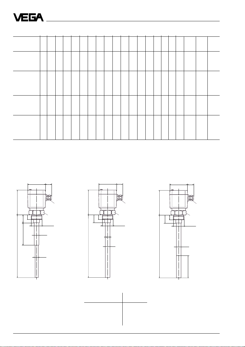
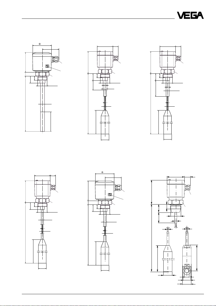
1.4 Dimensions
VEGACAP 11 (partly insulated)
80 x 110
~30
111
20
35
L1
L (max. 4000 mm)
Isolation length L1:
(VEGACAP 11 and VEGACAP 31)
PP: 100 mm
PTFE: 50 mm
StEx: max. 100 mm
Pg 13,5
SW 60
G 1½ A
Ø 20
Ø 15
VEGACAP 21 (fully insulated)
80 x 110A~30
111
20
35
L (max. 4000 mm)
Isolation A
PE 2.0 mm 20 mm
PTFE 2.0 mm 20 mm
PTFE 3.2 mm 16 mm
PFA 2.0 mm 20 mm
Pg 13,5
SW 60
G 1½ A
Outer-ø
VEGACAP 26 (fully insulated, for adhesive products)
LA = active length (standard
100 mm)
80 x 110 ~30
111
20
35
L (min.300, max. 4000 mm)
SW 60
G 1½ A
Ø 20
LA
Pg 13,5
10 VEGACAP
Page 11
Product description
VEGACAP 27 (fully insulated, for adhesive products, adjustment-free)
85
~76
90
20
20
35
L
Ø 20
M20x1,5
PA connection
SW 60
G 1½ A
LA
VEGACAP 34 (partly insulated)
80 x 110 ~30
VEGACAP 31 (partly insulated)
80 x 110 ~30
111
20
35
L1
L (max. 25.000 mm)
200
Ø 40
Pg 13,5
SW 60
G 1½ A
Ø 20
Ø 8
VEGACAP 35 (partly insulated, for adhesive products, adjustment-free)
85
~76
VEGACAP 33 (partly insulated)
80 x 110 ~30
111
20
35
L1
L (max. 25.000 mm)
200
Ø 40
Pg 13,5
SW 60
G 1½ A
Ø 15,5
Ø 8
VEGACAP 42 (fully insulated)
~30
80 x 110
111
20
35
L (max. 25.000 mm)
200
Ø 40
G 1½ A
Ø 11
Ø 6
SW 60
Pg 13,5
90
20
20
35
Ø 13,5
L
Ø 6
200
Ø 40
SW 60
G 1½ A
M20x1,5
PA
connection
111
20
35
100
∅3
L
200
∅40
Gravity weight
∅5
SW 60
PG 13.5
∅3
120
∅20
36
∅40
Fixing weight
VEGACAP 11
Page 12

Product description
VEGACAP 52 (fully insulated)
111
L
200
∅40
Gravity weight
∅8
20
35
80 x 110
Fixing weight
~30
Pg 13.5
SW 60
∅16
VEGACAP 84
80 x 110
~30
∅8
VEGACAP 53 (fully insulated)
111
20
35
∅6
L
125
∅20
36
∅40
200
∅40
Gravity weight
VEGACAP 97 (fully insulated, for adhesive products)
80 x 110
80 x 110
Fixing weight
~30
∅11
~30
Pg 13.5
SW 60
∅6
VEGACAP 82/
VEGACAP 92
(partly / fully insulated)
91
18,5
60
125
∅20
36
∅40
VEGACAP 98 (fully insulated, for adhesive products, adjustment-free)
80 x 110 ~30
Pg 13,5
6
Ø 90
Ø 125/4xØ18
Ø 165
85
~ 76
91
Pg 13.5
SW 60
65
D
111
L
LA = active length (90 mm)
SW 60
G 1½ A
ø33
LA
Pg13,5
9020
21
28
L (200 mm
standard)
LA = active length (90 mm)
G 1½ A
ø 33
LA
M20x1,5
PA
connection
SW 60
12 VEGACAP
Page 13

Product description
Temperature adapter
St / StSt
SW 60
20090
SW 60
Temperature adapter PA
for temperatures
up to 150°C, from
100°C only
Ø 60
7020
unpressurized
VEGACAP 60 (partly insulated, high-temperature
electrode)
L
111
200180
L1 Stützrohr (300)
80 x 110
~30
Pg 13,5
SW 60
23
G 1½ A
Ø 38
VEGACAP 61 (partly insulated, high-temperature
electrode)
L
111
200
180
L1 Stützrohr (300)
100
80 x 110
~30
Pg 13,5
SW 60
23
G 1½ A
Ø 38
Ø 8
Screening tube
SW 60
of St or 1.4571 with
closing cone of PP or
PTFE
L
Ø 38
Closing cone
10
Ø 15
VEGACAP 13
200
Ø 40
Page 14

Product description
1.5 Product temperature and operating pressure
The numbers in the tables relate to the numbers of the opposite illustrations. The pressure stated are valid for thread connections
G 11/2 A, NPT 11/2“ and R 11/2. Boltings DN 50
acc. to DIN 11 851 only up to max. 25 bar.
When using flange versions, give attention to
their respective nominal pressures. All electrodes are also suitable for vacuum (–1 bar).
Mechanical connection, 1.4571 (StSt)
Isolation
VEGACAP
11 - 1 3 - -
21 1-3-3
2)
21
26 - - 3 - 3
2)
26
27 - - 3 - 3
31 - 1 3 - -
33 - - 3 - -
34 unpressurized - - - 1 -
35 - - - 1 -
42 - - 2 - -
52 - - 3 - -
53 - - - 1 -
PE
PP
PTFE
PE/PA 12
PFA
--2--
--2--
bar
40
16
0
-30
bar
63
-50
-50
0
bar
63
25
0
bar
40
16
0
-10
60 80
60 80
˚C
˚C
VEGACAP 21, 35, 53:
PE and PE/PA 12
up to 16 bar
VEGACAP 34:
unpressurized
VEGACAP 42:
up to 16 bar
°C
100
100
Temperature
1)
adapter
VEGACAP 21, 35, 53:
PE and PE/PA 12
up to 16 bar
VEGACAP 34:
unpressurized
1
2
3
200
˚C
4
Mechanical connection, steel (St 37)
Isolation
VEGACAP
PE
PP
PTFE
PE/PA 12
PFA
11 - 4 6 - -
21 4-6-6
2)
21
--5--
26 - - 6 - 6
2)
26
--5--
27 - - 6 - 6
31 - 4 6 - -
33 - - 6 - -
34 unpressurized - - - 4 -
35 - - - 4 -
42 - - 5 - -
52 - - 6 - -
53 - - - 4 -
1)
2)
14 VEGACAP
bar
63
VEGACAP 42:
up to 16 bar
0
-10
bar
63
25
0
-10
100
˚C
100
Temperature
adapter
1)
Temperature adapter of PA up to 150°C, from
100°C unpressurized
Flange plated
5
6
200
˚C
Page 15

Product description
Mechanical connection, Aluminium
(VEGACAP 97, 98: PP)
Isolation
VEGACAP
11 - 7 8 - -
21 7-8-8
26 - - 8 - 8
27 - - 8 - 8
31 - 7 8 - -
33 - - 8 - -
34 unpressurized - - - 7 -
35 - - - 7 -
42 - - 8 - -
52 - - 8 - -
53 - - - 7 -
82 unpressurized - - 9 - -
84 unpressurized
92 - - 9 - -
97 - 7 - - -
98 - 7 - - -
PE
PP
PTFE
PE/PA 12
PFA
bar
16
0
-30
60 80
VEGACAP 34, 97, 98
unpressurized
˚C
7
8
bar
16
0
-30
VEGACAP 82, 82 R ExS: unpressurized
VEGACAP 92: up to 6 bar
bar
6
-20
0
100
˚C
100 150
˚C
Temperature
adapter
9
1)
0
StSt: up to -50°C
Steel: up to -10°C
100
200
with separate
housing
10
300
400
°C
High-temperature electrode
Isolation
VEGACAP
60 11
Ceramic
bar
10
-10
-50
61 11
Instruments with StEx approval
Mechanical connection, steel (St 37) or
1.4571 (StSt)
Isolation
VEGACAP
PP
PTFE
bar
40
0
-20
1)
Temperature adapter of PA up to 150°C, from
80
˚C
60
100°C unpressurized
11
11 R ExS 10 9
31 R ExS 10 9
82 R ExS unpressurized - 9
VEGACAP 15
Page 16

Mounting
1.6 Approvals
StEx (Zone 10)
Level detection
Instrument Oscillator Level switch Certificate
Capacitive VEGACAP E30 R ExS Signal conditioning in- BVS no. 95.Y.8001
11 R ExS.- strument not required,
31 R ExS.- compact instrument
82 R ExS.-
16 VEGACAP
Page 17

Mounting
;
;
;
;
;
;
;
;
;
;
;
;
;
;
;
;
;
;
;
;
;
;
;
;
;
;
;
;
;
;
;
;
;
;
;
;
;
;
;
;
;
;
;
;
;
;
;
;
;
;
;
;
;
;
;
;
;
;
;
;
;
;
;
;
;
;
;
;
;
;
;
;
;
;
;
;
;
;
;
;
;
;
;
;
;
;
;
;
;
;
;
;
;
;
;
;
;
;
;
;
;
;
;
;
;
;
;
;
;
;
;
;
;
;
;
;
;
;
;
;
;
;
;
;
;
;
;
;
;
;;
;;
;;
;;
;;
;;
;;
;;
;;
;;
;;
;;
;;
;;
;;
;;
;;
;;
;;
;;
;;
;;
;;
;;
;;
;;
;;
;;
;;
;;
;;
;;
;;
;;
;;
;;
;;
;;
;;
;;
;;
;;
;;
;;
;;
;;
;;
;;
;;
;;
;;
;;
;;
;;
;;
;;
;;
;;
;;
;;
;;
;;
;;
;;
;;
2 Mounting
2.1 Mounting instructions
Plate electrode
Install the plate electrode (VEGACAP 82, 92)
General
Generally, the instrument can be mounted in
any desired orientation. The instrument must
simply be mounted such that the electrode is
such that the electrode is flush to the vessel
wall. The wall thickness of the vessel should
not exceed 20 mm. Chamfer the inner edge
of the hole so that build-up can be avoided.
at the height of the requested switching point.
Various mediums and measurement specifications require different types of installation.
Shortening of the electrode
Hence, some instructions should be noted.
Rod electrodes
Fully insulated electrodes have fixed dimen-
Length of the electrode
Note at the time of ordering electrodes for
vertical installation, that the electrode must be
sions and thus must not be modified in their
dimensions. Any modification will destroy the
instrument.
immersed to the requested level according to
the electrical properties of the medium.
All partly insulated electrodes can be short-
ened, see 5.5 Shortening of the electrode.
Note that the switching point of vertically
installed, adjustment-free electrodes (VEGACAP 27, 35, 98) can vary in the range of
the active part.
The measuring probes are compensated to
the respective electrode length with the fac-
tory setting. If the electrode is to be short-
ened by more than 30 %, you should
recompensate the electrode. Call our service
department.
Lateral load
Make sure that the electrode is not subjected
to strong lateral forces. Mount VEGACAP at a
position in the vessel where no interferences
such as from e.g. stirrers, filling openings
etc. can occur (see fig. 2.1).
1
0
Fig. 2.1
VEGACAP 17
1
0
Cable electrodes
The cable electrodes VEGACAP 31, 33, 34
and 35 can be shortened afterwards (see fig.
2.2). See 5.5 Shortening of the electrode.
;;;
;;;
;;;
;;;
;;;
;;;
;;;
;;;
;;;
;;;
;;;
;;;
;;;
;;;
;;;
;;;
;;;
;;;
;;;
;;;
;;;
;;;
;;;
;;;
;;;
;;;
;;;
;;;
;;;
;;;
;;;
;;;
;;;
;;;
;;;
;;;
;;;
;;;
;;;
;;;
;;;
;;;
;;;
;;;
;;;
;;;
;;;
;;;
;;;
;;;
;;;
;;;
;;;
;;;
;;;
;;;
;;;
;;;
;;;
;;;
;;;
;;;
;;;
;;;
;;;
;;;
;;;
Fig. 2.2
Page 18

Mounting
Extracting forces
In case of strong extracting forces e.g. due
to material inflow, high tensile loads can be
caused.
In this case use for short meas. distances a
rod electrode, as generally a rod is more
stable. If due to the length or the installation
position a cable electrode should be necessary, the electrode should not be fixed but
just provided with a gravity weight, as the
cable can more easily follow the product
movements. Make sure that the electrode
cable does not touch the vessel wall.
Fasten the gravity weight of VEGACAP 35
with a plastic cable.
Pressure
In case of excess or low pressure in the
vessel, the mounting boss must be sealed on
the housing. Use the attached seal ring.
Check whether the seal ring is resistant
against the medium.
Isolating measures such as e.g., the covering of the thread with Teflon tape, can interrupt the necessary electrical connection in
metal vessels. In such case earth the electrode with an additional cable connection to
the vessel.
Aluminium vessel
In case of Aluminium vessels, an electrode
with steel thread should be used. The combination Aluminium on Aluminium should be
avoided, as the thread "seizes“ and cannot
be removed after some time without damage.
Horizontal mounting
The electrode can be mounted horizontally to
achieve an exact switching point for level
detection. We recommend mounting the
electrode approx. 20° inclined to the bottom
so that build-up is avoided (see fig. 2.4).
a.
Fig. 2.4
b.
20˚
Sheet
0
1
Moisture
When mounting outside, on cooled vessels or
in humid areas where the cleaning is done,
e.g. with steam or high pressure, the sealing
of the cable entry is very important. Use
cable with sufficient conductor cross-section
and tighten the cable entry very securely. For
cables with insufficient conductor crosssection, an appropriate reduction insert must
be used to ensure tightness.
Two different seal rings are attached to the
instrument to also enable reliable sealing of
cables with smaller diameter in the cable
entry. Use the smallest possible seal ring.
Turn the cable entries of the instrument downwards to avoid moisture ingress. For this
purpose the housing can be rotated by
approx. 330°. For vertically installed electrodes loop the connection line to the instrument housing downwards so that rain and
condensation water can drain off (see fig.
2.5).
18 VEGACAP
Page 19

Mounting
Fig. 2.5
Metal vessels
Make sure that the mechanical connection of
the instrument to the vessel is electrically
conductive, in order to ensure sufficient
grounding.
Use conductive seals such as e.g. copper,
lead etc. Isolating measures such as covering the thread with Teflon tape can interrupt
the necessary electrical connection. In this
case use the earth terminal on the housing to
connect the instrument to the vessel wall.
Non-conductive vessels
In non-conductive vessels, e.g. plastic tanks,
the second pole of the capacitor must be
provided separately, e.g. by a concentric
tube or earth rod.
Under ideal ground conditions (e.g. short
electrodes) the earth plates or concentric
tube can be omitted.
If the filling medium has not been grounded
separately (VEGACAP 27 and 35) and the
electrode is covered with a conductive. adhe-
sive medium (up to the mounting boss), the
full signal is triggered only when the medium
touches the threaded mounting boss and
gets grounded. With vertically installed sen-
sors therefore, a provision for grounding the
filling medium should be made.
Filling opening
Install the electrode such that it does not
protrude directly into a strong filling stream.
Should such a mounting location be neces-
sary, mount a suitable sheet metal cover
above or in front of the electrode e.g. L 80 x 8
DIN 1028, etc. (see fig. 2.4 a).
In abrasive solids, mounting acc. to fig. 2.4 b
has proven to be a good solution. A material
cornice forms on the concave protective
sheet, thus preventing unnecessary wear of
the sheet.
Mounting boss
Install the rod electrode (VEGACAP 11, 21,
26, 97) such that the electrode protrudes into
the vessel. When installed in a tube or a
socket, build-up can be caused which can
influence the measurement. This is particu-
larly true for viscous or adhesive products
(see fig. 2.6).
In case of longer sockets, use an electrode
for adhesive products (VEGACAP 26, 27, 35,
97, 98) or a screening tube.
When using a standard electrode, a suitable
earth plate is necessary. For this purpose
provide the largest possible earth plate, e.g.
wire braiding laminated into the vessel wall or
a metal foil glued to the vessel. Connect the
max. 80 mm
0
1
earth plates with the earth terminal on the
instrument housing (or on the hexagon).
Fig. 2.6
VEGACAP 19
Page 20

;;;;;;;;;;;
;;;;;;;;;;;;;;;;;;;;;;;;;;;;;;;;;;;;;;;;;;;;
;;;;;;;;;;;;;;;;;;;;;;;;;;;;;;;;;;;;;;;;;;;;
;;;;;;;;;;;;;;;;;;;;;;;;;;;;;;;;;;;;;;;;;;;;
;;;;;;;;;;;;;;;;;;;;;;;;;;;;;;;;;;;;;;;;;;;;
;;;;;;;;;;;;;;;;;;;;;;;;;;;;;;;;;;;;;;;;;;;;
;;;;;;;;;;;;;;;;;;;;;;;;;;;;;;;;;;;;;;;;;;;;
;;;;;;;;;;;;;;;;;;;;;;;;;;;;;;;;;;;;;;;;;;;;
;;;;;;;;;;;;;;;;;;;;;;;;;;;;;;;;;;;;;;;;;;;;
;;;;;;;;;;;;;;;;;;;;;;;;;;;;;;;;;;;;;;;;;;;;
;;;;;;;;;;;;;;;;;;;;;;;;;;;;;;;;;;;;;;;;;;;;
;;;;;;;;;;;;;;;;;;;;;;;;;;;;;;;;;;;;;;;;;;;;
;;;;;;;;;;;;;;;;;;;;;;;;;;;;;;;;;;;;;;;;;;;;
;;;;;;;;;;;;;;;;;;;;;;;;;;;;;;;;;;;;;;;;;;;;
;;;;;;;;;;;;;;;;;;;;;;;;;;;;;;;;;;;;;;;;;;;;
;;;;;;;;;;;;;;;;;;;;;;;;;;;;;;;;;;;;;;;;;;;;
;;;;;;;;;;;;;;;;;;;;;;;;;;;;;;;;;;;;;;;;;;;;
;;;;;;;;;;;;;;;;;;;;;;;;;;;;;;;;;;;;;;;;;;;;
;;;;;;;;;;;;;;;;;;;;;;;;;;;;;;;;;;;;;;;;;;;;
;;;;;;;;;;;;;;;;;;;;;;;;;;;;;;;;;;;;;;;;;;;;
;;;;;;;;;;;;;;;;;;;;;;;;;;;;;;;;;;;;;;;;;;;;
;;;;;;;;;;;;;;;;;;;;;;;;;;;;;;;;;;;;;;;;;;;;
;;;;;;;;;;;;;;;;;;;;;;;;;;;;;;;;;;;;;;;;;;;;
;;;;;;;;;;;;;;;;;;;;;;;;;;;;;;;;;;;;;;;;;;;;
;;;;;;;;;;;;;;;;;;;;;;;;;;;;;;;;;;;;;;;;;;;;
;;;;;;;;;;;;;;;;;;;;;;;;;;;;;;;;;;;;;;;;;;;;
;;;;;;;;;;;;;;;;;;;;;;;;;;;;;;;;;;;;;;;;;;;;
;;;;;;;;;;;;;;;;;;;;;;;;;;;;;;;;;;;;;;;;;;;;
;;;;;;;;;;;;;;;;;;;;;;;;;;;;;;;;;;;;;;;;;;;;
;;;;;;;;;;;;;;;;;;;;;;;;;;;;;;;;;;;;;;;;;;;;
;;;;;;;;;;;;;;;;;;;;;;;;;;;;;;;;;;;;;;;;;;;;
;;;;;;;
;;;;;;;;;;;;;;;;;;;;;;;;;;;;;;
;;;;;
;;;;;;;;;;;;;;;;;;;;;;;;;;;;;;
;;;;;
;;;;;;;;;;;;;;;;;;;;;;;;;;;;;;;;;;;;;;;;;;;;
;;;;;;;;;;;;;;;;;;;;;;;;;;;;;;;;;;;;;;;;;;;;
;;;;;;;;;;;;;;;;;;;;;;;;;;;;;;;;;;;;;;;;;;;;
;;;;;;;;;;;;;;;;;;;;;;;;;;;;;;;;;;;;;;;;;;;;
;;;;;;;;;;;;;;;;;;;;;;;;;;;;;;;;;;;;;;;;;;;;
;;;;;;;;;;;;;;;;;;;;;;;;;;;;;;;;;;;;;;;;;;;;
;;;;;;;;;;;;;;;;;;;;;;;;;;;;;;;;;;;;;;;;;;;;
;;;;;;;;;;;;;;;;;;;;;;;;;;;;;;;;;;;;;;;;;;;;
;;;;;;;;;;;;;;;;;;;;;;;;;;;;;;;;;;;;;;;;;;;;
;;;;;;;;;;;;;;;;;;;;;;;;;;;;;;;;;;;;;;;;;;;;
;;;;;;;;;;;;;;;;;;;;;;;;;;;;;;;;;;;;;;;;;;;;
;;;;;;;;;;;;;;;;;;;;;;;;;;;;;;;;;;;;;;;;;;;;
;;;;;;;;;;;;;;;;;;;;;;;;;;;;;;;;;;;;;;;;;;;;
;;;;;;;;;;;;;;;;;;;;;;;;;;;;;;;;;;;;;;;;;;;;
;;;;;;;;;;;;;;;;;;;;;;;;;;;;;;;;;;;;;;;;;;;;
;;;;;;;;;;;;;;;;;;;;;;;;;;;;;;;;;;;;;;;;;;;;
;;;;;;;;;;;;;;;;;;;;;;;;;;;;;;;;;;;;;;;;;;;;
;;;;;;;;;;;;;;;;;;;;;;;;;;;;;;;;;;;;;;;;;;;;
;;;;;;;;;;;;;;;;;;;;;;;;;;;;;;;;;;;;;;;;;;;;
;;;;;;;;;;;;;;;;;;;;;;;;;;;;;;;;;;;;;;;;;;;;
;;;;;;;;;;;;;;;;;;;;;;;;;;;;;;;;;;;;;;;;;;;;
;;;;;;;;;;;;;;;;;;;;;;;;;;;;;;;;;;;;;;;;;;;;
;;;;;;;;;;;;;;;;;;;;;;;;;;;;;;;;;;;;;;;;;;;;
;;;;;;;;;;;;;;;;;;;;;;;;;;;;;;;;;;;;;;;;;;;;
;;;;;;;;;;;;;;;;;;;;;;;;;;;;;;;;;;;;;;;;;;;;
;;;;;;;;;;;;;;;;;;;;;;;;;;;;;;;;;;;;;;;;;;;;
;;;;;;;;;;;;;;;;;;;;;;;;;;;;;;;;;;;;;;;;;;;;
;;;;;;;;;;;;;;;;;;;;;;;;;;;;;;;;;;;;;;;;;;;;
;;;;;;;;;;;;;;;;;;;;;;;;;;;;;;;;;;;;;;;;;;;;
;;;;;;;;;;;;;;
;;;;;;;;;;;;;;;;;;;;;;;;;;;;;;
;;;;;
;;;;;;;;;;;;;;;;;;;;;;;;;;
;;
;;;;;
;;;;;;;;;;;
Mounting
Material cone
Note when installing the electrodes in the
vessel that material cones can form in solids,
thus changing the switching point. We recommend selecting a mounting location where
the electrode detects an average value of the
material cone.
The measuring probe must be installed at a
location which takes the filling and emptying
apertures of the vessel into account. To compensate meas. errors caused by the material
cone, you should install the electrode at a
distance of approx. d/10 from the vessel wall.
You should keep a min. distance of approx.
20 cm (see fig. 2.7 and 2.8).
Filling
Emptying
Fig. 2.7 Material cone, filling and emptying centered
Filling Emptying
3
10
d
d
1
2
1 Emptying
2 Filling opening
3 Capacitive
electrode
Fig. 2.8 Material cone, filling centered, emptying
lateral
20 VEGACAP
Page 21

Electrical connection
3 Electrical connection
3.1 Connection instructions
Danger
Switch off the power supply before starting
connection work.
The electrical connection must be carried out
in accordance with the integrated oscillator
version. Connect mains voltage acc. to the
following connection plans.
Note
Give attention when replacing the housing
cover that the inspection glass is above the
control lamp (LED).
Note
If strong electromagnetic interference is expected, we recommend the use of screened
cable. The screening of the cable should only
be earthed only on the sensor end (electrode).
As a rule, connect VEGACAP with vessel
ground (PA). To do this, use the ground terminal on the housing (VEGACAP 27, 35 and
98) or the thread on the hexagon surfaces of
the mounting boss (screw
M4 x 5). On VEGACAP 97 terminal 3 must be
connected. This connection is used to draw
the ground potential as well as to drain off
electrostatic discharge.
1
2
3
1 Housing cover
2 Oscillator, e.g. CAP E30
3 Housing
3.2 Connection plan
Non-contact switch (CAP E30 C)
123
AC L1 N Earth
DC + –
or
DC – +
Voltage supply: 20 … 250 V AC,
50/60 Hz; 20 … 250 V DC (for further infor-
mation see technical data)
VEGACAP 21
Page 22

Electrical connection
For direct control of relays, contactors, magnetic valves, signallers, horns etc. It must not
be operated without connected load (connected in series) as the oscillator would be
destroyed if directly connected to mains. Not
suitable for connection to low voltage PLCinputs. The domestic current is briefly lowered below 1 mA when switching off the load,
so that contactors, the holding current of
which is lower than the permanently flowing
domestic current of the electronics, nevertheless can be switched off reliably.
Floating transistor output (CAP E30 T)
-
2
1
3 4+5
Voltage supply: 10 … 55 V DC
(for further information see the following
switching examples as well as the technical
data)
Switching examples
+- +
-
- +- +
2
1
3 4 5
+
NPN action PNP action
-
+
2
1
3 4 5
+
-
+
The transistor switches a second voltage
source with the same reference potential to
the binary input of a PLC or to an electrical
load. Through different connection of the
consumer (load), PNP or NPN action can be
preset.
+- +
1
2
-
3 4 5
2
1
3 4 5
2
1
3 4 5 123 4 5
-
--
+
+
NPN action PNP action
+
-
+
The transistor switches a second, galvanically separated voltage source to the binary
+
NPN action PNP action
-
+
-
input of a PLC or to an electrical load.
Through different connection of the consumer
(load), PNP or NPN action can be preset.
The transistor switches the supply voltage of
the oscillator to the binary input of a PLC or to
an electrical load. Through different connection of the consumer (load), PNP or NPN
action can be preset.
22 VEGACAP
Page 23

Electrical connection
Control of alternating current loads
- +
2
1
3 4 5
~
+
-
~
The transistor switches a galvanically separated alternating voltage 10 … 42 V AC to a
load.
- +
123 4 5
~
~
Floating relay output (CAP E30 R)
Relay output
Power supply
Voltage supply: 20 … 250 V AC,
50/60 Hz; 20 … 72 V DC (for further informa-
tion see technical data)
Is used to switch external voltage sources to
relays, contactors, magnet valves, signallers,
horns etc.
Floating relay output (CAP E31 R)
+
-
L1
N
123456
78
Relay output
Relay output
Power supply
The transistor switches an alternating voltage
10 … 42 V AC, which is also supply voltage,
to a load.
Voltage supply: 20 … 250 V AC,
50/60 Hz; 20 … 72 V DC (for further informa-
tion see technical data)
Note
The transistor outputs of several VEGACAP
can be switched in series or in parallel to
connect the signals logically. The wiring must
be done so that terminal 2 has a higher volt-
In conjunction with oscillator CAP E31 R, the
measuring probes VEGACAP 27, 35 and 98
are adjustment-free and suitable for adhesive
products.
age than terminal 3.
With double relay (DPDT), i.e. both relays
carry out the same switching function, e.g.
simultaneous control of a horn and a magnet
valve.
VEGACAP 23
Page 24

4 Setup
Setup
4.1 Adjustment elements
Oscillator CAP E30
1
1
6
1 - Type plate (oscillator)
2 - Control lamp (LED)
3 - Terminals
4 - A/B-switch
5 - Potentiometer
6 - Changeover switch
Fig. 4.1
The switching mode of the electronics can be
checked with closed housing (2) (only plastic
housing) see "4.3 Functions chart“. To adjust
VEGACAP, loosen the four screws on the
instrument top with a screwdriver and remove the housing cover.
2
3
5
4
With the potentiometer (5) and the changeover switch (6) you can modify the switching
point of the electrode or adapt the sensitivity
of the electrode to the electrical properties of
the medium and the conditions in the vessel.
This is necessary so that the level switch can
reliably detect e.g. products with very low or
very high dielectric constant (DK = dielectric
constant).
On the oscillator CAP E31 R, this adjustment
is not necessary.
Capacitance range
(oscillators CAP E30 C, R, T)
- range 1 0 … 20 pF sensitive
- range 2 0 … 85 PF …
- range 3 0 … 450 pF insensitive
Examples of DK values:
Air = 1, Oil = 2, Acetone = 20, Water = 81 etc.
Turn the potentiometer anticlockwise to increase the sensitivity of the electrode.
Note
When positioning the housing cover, make
sure that the inspection glass is above the
control lamp (LED).
The following adjustments are possible on
oscillator CAP E30:
- A/B-mode
- switching point adjustment
- range selection.
With the A/B-switch (4) you can change the
switching mode of the non-contact switch
(C), the relay (R) or the transistors (T). You
can thus adjust the requested mode acc. to
"4.3 Functions chart“.
A - Max. detection or overfill protection,
B - min. detection or detection against dry
running of pumps.
24 VEGACAP
Page 25

Setup
4.2 Switching point adjustment
With the A/B-switch (4) you can choose the
mode of VEGACAP - whether the level switch
should be used as max. detection A (overfill
protection) or min. detection B (protection
against dry running of pumps). As a rule, the
switching point adjustment is only possible in
assembled condition. The numbers in
parantheses relate to figure "4.1 Adjustment
elements“.
Horizontally mounted electrodes,
electrodes for adhesive products, plate
electrodes, angled electrodes
(with oscillator CAP E30…, fig.
(VEGACAP 11, 21, 26, 60, 61, 82, 84, 92, 97)
Mode A /
• Make sure that the test switch (outside on
the housing - option) is set to position 0.
• Set the A/B-switch (4) to mode A
• Set the changeover switch (6) to position 1.
• Make sure that the electrode is uncovered.
• Turn the potentiometer (5) to 0; the control
lamp (2) lights
• Turn the potentiometer (5) very slowly
clockwise until the control lamp extinguishes
switching point. If the lamp does not extinguish
the next higher stage and repeat the adjustment with the potentiometer until the
control lamp extinguishes
• Note the position of the potentiometer (5).
In some cases the lowest range (range 1 =
highest sensitivity) is not sufficient to adjust
the full switching point. This would require
another filling procedure.
For this reason, we recommend adjusting
and noting the empty switching point in all
three ranges.
[mode B]
[extinguishes]
[lights]
, to determine the empty
[light]
, set the changeover switch to
4.1
.
[lights]
)
[B]
.
.
- Set the changeover switch (6) to the next
higher position and repeat the adjustment. Note the value for the next higher
range.
Empty Full
adjustment adjustment
Range 1
Range 2
Range 3
- Set the changeover switch (6) to the
lowest range where the control lamp
extinguishes
• Fill the vessel until the electrode is completely covered.
• Turn the potentiometer (5) very slowly
clockwise until the control lamp extinguishes
potentiometer (5). We recommend documenting the value of the empty and full
switching point as well as the range.
• If the lamp does not extinguish
the changeover switch (6) to the next
higher stage and repeat the adjustment
with the potentiometer until the control lamp
extinguishes
• Set the potentiometer (5) to the average
value of the two noted values.
The measuring system is now ready for
operation.
• If you cannot find the full switching point in
one of the ranges, we recommend setting
the changeover switch (6) to the lowest
range in which you have found the empty
switching point. Set the potentiometer (5) to
the average value between empty switching point and 10.
[lights]
.
[lights]
. Note the position of the
[lights]
.
[light]
, set
VEGACAP 25
Page 26

Setup
Vertically mounted electrodes
(with oscillator CAP E30…, fig. 4.1
(VEGACAP 11, 21, 31, 33, 34, 42, 52, 53, 60,
61)
Mode A
(Max. detection)
• Make sure that the test switch (outside on
the housing - option) is set to position 0.
• Set the A/B-switch (4) to mode A.
• Set the changeover switch (6) to position 1.
• Fill the vessel to the requested level.
• Turn the potentiometer (5) to 10; the control
lamp (2) extinguishes.
• Turn the potentiometer (5) very slowly
anticlockwise until the control lamp (2)
lights. If the control lamp does not light, set
the changeover switch (6) to the next
higher stage and repeat the adjustment
with the potentiometer until the control lamp
lights. The measuring system is ready for
operation.
Mode B
(Min. detection)
• Make sure that the test switch (outside on
the housing - option) is set to position 0.
• Set the A/B-switch (4) to mode B.
• Set the changeover switch (6) to position 1.
• Lower the product down to the requested
min. level.
• Turn the potentiometer (5) to 0; the control
lamp (2) extinguishes.
• Turn the potentiometer very slowly clockwise until the control lamp (2) lights. If the
control lamp does not light, set the
changeover switch (6) to the next higher
stage and repeat the adjustment with the
potentiometer until the control lamp lights.
The measuring system is ready for operation.
)
Adjustment-free electrodes for adhesive products
(with oscillator CAP E31 R, fig. 4.2)
3
6
2
1
4
5
1 - Type plate (oscillator)
2 - Control lamp (LED)
3 - Terminals
4 - A/B-switch
5 - Potentiometer
6 - Strap
Fig. 4.2
In general, the measuring probes VEGACAP
27, 35 and 98 (up to max. 3 m) in conjunction
with oscillator CAP E31 R no longer require
adjustment (see exceptions on the following
pages). The vessel must not be filled for the
adjustment.
With the A/B-switch (4) you can choose the
mode of VEGACAP, whether the level switch
should be used as max. detection A (overfill
protection) or as min. detection B (protection
against dry running of pumps).
These measuring probes have an active
length and a screening segment. Due to this
screening segment, the standing capacitance caused by the vessel after the installation of the electrode is almost completely
compensated.
26 VEGACAP
Page 27

Setup
The oscillator is factory-adjusted to the basic
capacitance of the electrode. The relay output switches when the active part of the electrode is covered. Varying dielectric constants
of products, such as e.g. in mixing vessels
have no effect on the switching accuracy
within the active length. The selection of the
electrode length is thus very important since
the length determines the switching point
which cannot be shifted on the electrode
(exception: the electrode of VEGACAP 35
can be shortened).
The electrodes can be fabricated with different high-resistance insulating materials and
are thus suitable for corrosive products (see
also "1.2 Types and versions“).
The electrodes VEGACAP 27, 35 and 98 are
also unaffected by buildup.
Exceptions
In rare cases, e.g. in pipelines or when the
electrode is mounted very close to the vessel
wall or where high standing capacitances
exceed the preadjustment of VEGACAP, it
can happen that the electrode signals overfilling (covered) even if the electrode is uncovered. The oscillator of VEGACAP must be
readjusted.
In the following cases, a new adjustment is
necessary:
- in case of electrodes with a length of more
than 3 m
- in case of cramped installation conditions
with high standing capacitance (pipes
etc.),
- in products with a very low dielectric constant
- after shortening of the cable electrode
VEGACAP 35 by more than 0.5 m,
- after exchange of the oscillator.
New adjustment
• Make sure that the electrode is uncovered.
• Push through the adhesive cover, as on
figure 4.3, with a screwdriver.
• Turn the potentiometer first anticlockwise
until the control lamp signals the condition
„covered“ (max. 20 turns).
- mode A (overfill protection) control lamp lights
- mode B (dry run protection) control lamp extinguishes
If this condition has already been reached,
continue with the following item.
• Turn the potentiometer very slowly (due to
the integration time) clockwise until the
control lamp signals the condition „uncovered“:
- mode A (overfill protection) control lamp extinguishes
- mode B (dry run protection) control lamp lights
• Then turn the potentiometer clockwise acc.
to the following table. The instrument is
ready for operation
Sensitivity
Standard very
sensitive
VEGACAP DK ³ 2 DK ³ 1.5
27, 98 2.0 turns 1 turn
VEGACAP DK ³ 1.5
35 2.5 turns
Fig. 4.3
VEGACAP 27
Page 28

Note
For the measurement of products with very
low dielectric constant, the number of turns
can be reduced to 1. Note, however, that this
adjustment is too sensitive for conductive,
adhesive products.
Note
Make sure when positioning the housing
cover that the inspection glass is above the
control lamp (LED).
Setup
28 VEGACAP
Page 29

Setup
5
(8)
3
(6)4(7)
4.3 Functions chart
The following chart gives a survey on the switching conditions dependent on the adjusted
mode and level.
Level Switching condition Control
CAP E30 C CAP E30 R CAP E31 R CAP E30 T lamp
Mode A Transistor
6
4
(7)5(8)
21
3
(9)
(6)4(7)
Switch Relay Relay
closed energized energized
6
4
(9)
(7)5(8)
21
Relay Relay
Switch open deenergized deenergized
Mode B Transistor
4
21
(7)5(8)
3
6
(6)4(7)
(9)
Switch Relay Relay
closed energized energized
4
(7)5(8)
21
Relay Relay
(6)4(7)
(9)
3
6
Switch open deenergized deenergized
Failure of the individual Transistor
supply blocks
voltage
4
(7)5(8)
21
Relay Relay
3
6
(6)4(7)
(9)
Switch open deenergized deenergized
5
(8)
5
(8)
5
(8)
(8)
conductive
Transistor
blocks
conductive
Transistor
blocks
5
VEGACAP
VEGACAP 29
Page 30

5 Diagnostics
Diagnostics
5.1 Simulation
Test switch (option with E30 R, C, T)
As an option, a test switch can be integrated
in the housing to simulate a switching condition.
By turning on the test switch, an additional
capacitance is provided. Through this, the
function of the oscillator and the connected
instruments can be tested.
The numbers in parantheses relate to the
illustration "Adjustment elements“.
Note
When the changeover switch (6) is set to
position 3, it is possible that the additional
capacitance is not sufficient to carry out a
test.
The test switch can only be used for simulation of a max. level (overfill protection).
Test
• Make sure that the A/B-switch (4) is set to
position A. In normal operation, the test
switch is set to position 0.
• Set the test switch to position 1. Turning the
test switch to position 1 increases the capacitance of the uncovered electrode,
causing the oscillator to respond and trigger an alarm signal; the control lamp (2)
lights and the connected instruments are
activated.
Note
It is absolutely necessary to set the test
switch to its initial position (position 0) after
the test.
5.2 Maintenance
The instrument is maintenance free.
5.3 Repair
Repair work usually involves opening the
instrument to diagnose and correct defects.
For safety and warranty reasons, any internal
work on the instrument, apart from installation
and wiring, must be carried out only by
VEGA personnel.
In case of a defect, please return the respective instrument with a short description of the
error to our repair department.
1
0
Fig. 5.1
30 VEGACAP
Page 31

Diagnostics
5.4 Exchange of electronics
• Loosen the four screws with a screwdriver
and open the housing cover.
• Loosen the two screws and remove the old
electronics.
• Insert the new oscillator.
• Carry out an adjustment. The instruction is
given under "4.2 Switching point adjustment“.
5.5 Shortening of the electrodes
Shortening of the electrode
Rod electrodes
Fully insulated electrodes have fixed dimensions and must therefore not be modified in
their dimensions. Any modification will destroy the instrument.
All partly insulated electrodes can be shortened. The measuring probes are compensated to the appropriate electrode length with
the factory setting. If the probe is shortened
by more than 30 %, it should be recompensated. Call our service department.
Cable electrodes
The cable electrodes VEGACAP 31, 33, 34
and 35 can be shortened afterwards.
• Shorten the electrode cable with a metal
cutting saw or a cutting-off wheel. Insulated
cable must not be tinned since it cannot
come unravelled.
• Insert the cable into the hole of the gravity
weight (insulated cables: with the insulation) and clamp the cable with the two set
screws. With insulated electrode cable, the
tips of the two set screws must penetrate
the cable insulation to ensure contact of the
gravity weight with the metal cable.
• Carry out an adjustment. The instructions
can be found under "4.1 Adjustment“.
If the cable is shortened considerably, it may
not be possible to carry out an adjustment
with the measuring probe. In this case, the
measuring probe must be recompensated.
Note the serial number of the measuring
probe and call one of our technicians.
Instructions for shortening VEGACAP 31,
33 and 34
• Loosen the two set screws on the gravity
weight (hexagon socket) and remove
them.
• Pull the cable out of the gravity weight.
• To avoid fraying the steel cable during
cutting, you must tin the cable approx.
5 cm around the cutting position with a
soldering iron or blowtorch, or tightly bind
the cable together with a wire.
VEGACAP 31
Page 32

Instructions for shortening VEGACAP 35
VEGACAP 35 can be shortened by any
amount. Recompensation is not necessary
(see fig. 5.2)
If the measuring probes are shortened by
more than 0.5 m, an empty adjustment must
be carried out. The instructions can be found
under „4.2 Switching point adjustments/New
adjustment“.
• Loosen the outer set screw (8).
• Unscrew the lower part of the weight (7).
• Shift the upper part of the weight (1), the
four O-rings (2) and the isolating socket
(3) on the cable upward above the planned
cutting point.
• Remove the isolating sleeve (6) from the
terminal bush (4).
• Loosen the two set screws (5) on the terminal bush (4) and pull out the cable.
• Shorten the electrode cable with a metal
cutting saw or a cutting-off wheel to the
requested length.
• Shorten the cable insulation by 60 mm with
a sharp knife.
• Push the terminal bush (4) onto the cable
(with the chamfered side first) with a rotating movement.
Make sure that the cable is flush with the
lower side of the terminal bush (4).
• Fasten the cable with the two set screws
(5).
Make sure that the screen of the electrode
cable has no contact to the inner steel
cable.
• Push the isolating sleeve (6) onto the terminal bush (4).
• Slide the upper part of weight (1) back
against the lower part of weight (7) and
screw the two parts together.
• Secure the upper part of weight (1) with
the outer set screw (8).
• Carry out an adjustment. The instructions
can be found under "4.2 Switching point
adjustment“.
1 Upper part of weight
2 O-rings
3 Isolating socket
4 Terminal bush
5 Set screws
6 Isolating bushing
7 Lower part of weight
8 Set screw
Fig. 5.2
Diagnostics
1
8
2
3
4
5
6
7
32 VEGACAP
Page 33

Diagnostics
5.6 Failure rectification
Failure Measure, failure rectification
No function or Make sure with Ex-systems that the Ex-protection is not influenced by
defective switching the meas. instruments.
function Check the following possible causes of failure:
- shortcircuit
- sensor not correctly connected
- sensor line interrupted
- supply voltage too low
Push the A/B-switch on the oscillator. The relay output of VEGACAP
switches and the control lamp (LED) changes condition. If the relay
output does not switch, the sensor, or rather the oscillator, is defective.
Reed
contact
C
K
Screen
3
4
7
1
6
C
C
M
1MΩ
T
CAP E30 R
CT - Test capacitor
CM - Meas. capacitor
CK - Compensation capacitor
VEGACAP 33
Page 34

Diagnostics
C
PH
7
3
1 MΩ
4
1M
6
C
M
CAP E31 R
CM - Meas. capacitor
CPH- Phase shifting capacitor
Check the internal connections:
• Remove the housing cover.
• Loosen the three screws with a screwdriver and remove the oscillator
from the housing.
• Measure with an ohmmeter (range MW) the resistance values be-
tween the following contacts:
Contact 4 to middle pin (1)
The resistance must be 1 MW.
If the resistance is less, it means there is moisture in the housing or a
failure of the electrode insulation. A possible reason could be a
noninsulated electrode which is used in conductive (moist) product.
If the resistance is higher or if the connection is interrupted, the reason
is usually a bonding failure in the adapter plate or a resistor defective
due to strong electrostatic discharge.
In both cases, the measuring probe must be repaired by VEGA.
34 VEGACAP
Page 35

Diagnostics
Contact 4 to vessel
The electrical connection between contact 4 and the metal vessel (not
mounting boss or electrode flange) should be as good as possible.
Measure with an ohmmeter (range very low) the resistance value between contact 4 and the vessel.
• Shortcircuit (0 … 3 W), optimum connection
• Resistance > 3 W
- corrosion on the mounting boss or flange
- possibly the mounting boss was covered with Teflon tape or
something similar
Check the connection to the vessel. If there is no connection, you can
connect a line from the external grounding terminal to the vessel.
Make sure that coated flanges are always connected via the earth
terminal to the vessel.
Contact 7 to middle pin (1)
The resistance must be infinite (>10 MW).
If the resistance is less, moisture has entered, or the compensation
capacitor or the phase shifting capacitor (CAP E31R) are defective.
Contact 3 to 4
On electrodes without screen the resistance is infinite (>10 MW). On
VEGACAP 26, 27, 35 and 98 the resistance must be 1 MW. In case of
lower values, the electrode insulation is defective or moisture entered
the instrument housing.
In case of higher values, a bonding failure in the adapter plate or a
defective resistor is likely the cause.
If you cannot detect a failure in the measuring probe, exchange the
oscillator with one of the same type (if available) or return the probe for
repair to VEGA.
If the failure does not disappear after inserting the new oscillator, you
have to carry out a new adjustment (because of production tolerances
of the oscillators).
Note:
Make sure when positioning the housing cover that the inspection glass
is above the control lamp (LED).
VEGACAP 35
Page 36

VEGA Grieshaber KG
Am Hohenstein 113
D-77761 Schiltach
Phone (0 78 36) 50 - 0
Fax (0 78 36) 50 - 201
E-Mail info@de.vega.com
www.vega.com
ISO 9001
All statements concerning scope of delivery, application, practical
use and operating conditions of the sensors and processing systems correspond to the latest information at the time of printing.
Technical data subject to alterations
2.17 610 / September 2000
 Loading...