

Page 1
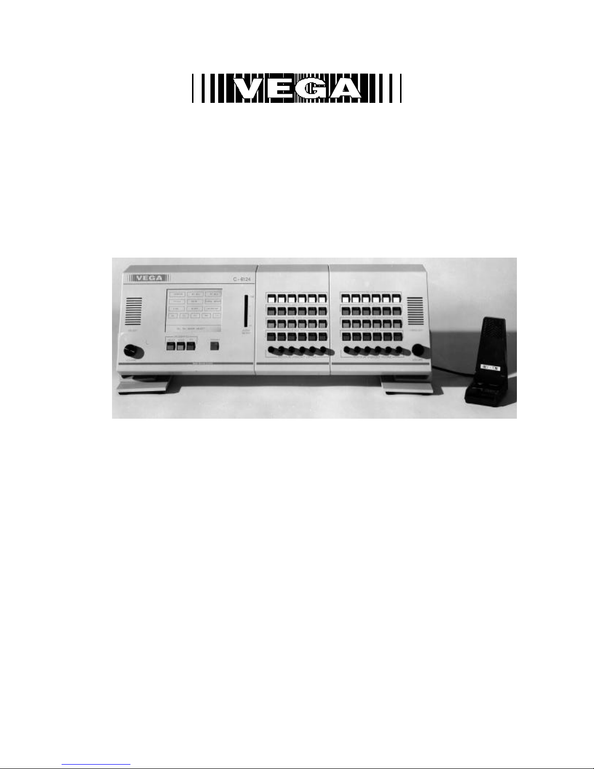
Model C-6124
Radio Control Console
12/10/01
Technical Manual
098-0371J
Page 2

Remote Control Console ii
Overview
1. Introduction 1
2. Hardware Overview 2
3. Controls and Indicators 4
4. Functional Description 14
5. Programming the C-6124 system 22
6. TLM Description 46
7. PLM Description 55
8. UIM (User Interface Module) Description 62
9. Sample setup procedure 67
10. Warranty, Service, Repair, and Comments 72
11. Specifications 73
The C-6124 uses microphone processor firmware that is fully year 2000 compliant
NOTE:
Page 3

iii Vega’s C6124
Contents in Detail
1. Introduction 1
2. Hardware Overview 2
2.1 User Interface Module (UIM) 2
2.2 Switch/Bus Module (SBM) 2
2.3 End Bus Module (EBM) 3
2.4 Tone Line Module (TLM) 3
2.5 Dial -Up Line & Phone Line Modules (PLM/DLM) 3
3. Controls and Indicators 4
3.1 Front Panel 4
3.2 Common Controls and Indicators 5
3.3 Touchscreen Examples 6
3.4 Tone Line Module (TLM) 9
3.5 Phone Line Module (PLM) 11
3.6 Dial -up line Module (DLM) 12
4. Functional Description 14
4.1 Touchscreen 14
4.2 Tone Lines (TLM) 19
4.3 Dial -up and Phone Lines (DLM/PLM) 20
4.4 Crosspatch Operation 21
5. Programming the C-6124 system 22
5.1 Programming at the System Level - Parameter Explanation 23
5.1.1 Memory Dial Name Editing 25
5.1.2 Memory Dial Number Editing 26
5.1.3 Simulcast Group Name Editing 27
5.1.4 Crosspatch Group Name Editing 28
5.1.5 Simulcast Group Assignments 29
5.1.6 Crosspatch Group Assignment 30
5.1.7 Parallel Crosspatch Notification and Mute Duration 31
5.1.8 Function Tone Parameters 32
5.1.9 RX Block 33
5.1.10 TX Block 34
5.2 Programming the Tone Line Module – Parameter Explanation 35
5.2.1 Accessing the Programming Screens 37
5.2.2 Card ID Number 38
5.2.3 Edit Line Names 38
5.2.4 Select Call Programming 39
5.2.5 LAM Flash Period Programming 40
5.2.6 Function Tone Block Programming 41
5.2.7 Crossmute Programming 42
5.3 Programming the Phone Line Module – Parameter Explanation 43
5.3.1 Accessing the Programming Screens 44
5.3.2 Card ID Number 45
6. TLM (Tone Line Module) Description 46
6.1 Introduction/Default Settings 46
6.2 Input/Output Pins 46
6.2.1 Line Jack 46
6.2.2 Recorder output 46
6.2.3 Multiple Consoles / Parallel OPERATION 46
6.3 Feature Description 47
6.3.1 Crossmute 47
6.3.1.1 Logic Crossmute 47
6.3.1.2 Tone Based Crossmute 47
6.3.2 E&M/ Local Control (PTT dry relay closure) 47
6.3.3 Four Wire Mode 48
6.3.3.1 RX Side Settings 48
Page 4

Remote Control Console iv
6.3.3.2 TX Side Settings 48
6.3.3.3 Transmit Monitor 48
6.3.4 Two Wire Mode 49
6.3.5 Recorder Output 49
6.3.6 Squelch Control 49
6.4 Level Adjustments 50
6.4.1 Transmit Side Adjustments 50
6.4.1.1 Microphone Audio 50
6.4.1.2 Crosspatch Transmit Audio 51
6.4.1.3 Transmit Output Drive 51
6.4.1.4 Tone Level 51
6.4.1.5 TX Notch Filter 51
6.4.1.6 DTMF Output Level 51
6.4.2 Receive Side Adjustments 51
6.4.2.1 Receive Input 51
6.4.2.2 Automatic Level Control 52
6.4.2.3 Line Activity Monitor 52
6.4.2.4 TX Monitor 52
6.4.2.5 Internal Bus Level 52
6.4.2.6 Recorder Output 52
6.4.2.7 RX Notch Filter 52
6.5 Jumper Setting Diagram and Table 53-54
7. PLM (Phone Line Module) Description 55
7.1 Introduction/Default Settings 55
7.2 Input/Output Pins 55
7.2.1 Line Jack 55
7.2.2 Recorder Output 55
7.3 Standard Operation 55
7.3.1 Phone Module (PLM) 55
7.3.2 Dial -up Module (DLM) 55
7.3.3 Recorder Output 55
7.3.4 Squelch Control 55
7.3.5 Parallel Line Off-Hook 56
7.4 Level Adjustments 56
7.4.1 Transmit Side Adjustments 56
7.4.1.1 Microphone Audio 57
7.4.1.2 Crosspatch Transmit Audio 57
7.4.1.3 Transmit Output Driver 57
7.4.1.4 TX Notch Filter 57
7.4.2 Receive Side Adjustments 57
7.4.2.1 Receive Input 58
7.4.2.2 Line Activity Monitor 58
7.4.2.3 Bus Output Level 58
7.4.2.4 Recorder Output 58
7.4.2.5 RX Notch Filter 58
7.5 Jumper Settings 59
7.6 FCC Notice 60
7.7 Industry Canada Notice 61
8. UIM (User Interface Module) Description 62
8.1 Introduction 62
8.1.1 UIM Digital 62
8.1.2 UIM Analog 62
8.2 Input, Outputs, and their Adjustments 62
Note: Unless otherwise specified, all connectors are on the UIM Analog board and accessible from the
outside of the back panel and all adjustments are on the UIM Analog board.
8.2.1 Internal DC Power 62
8.2.2 External DC Power 62
8.2.3 Footswitch 62
Page 5

v Vega’s C6124
8.2.4 Auxiliary Inputs 62
8.2.4.1 Auxiliary Voice Path 62
8.2.4.2 Auxiliary Audio Path 62
8.2.5 Recorder Outputs 63
8.2.5.1 Select Recorder 63
8.2.5.2 Unselect Recorder 63
8.2.5.3 Crosspatch Recorder 63
8.2.6 Auxiliary Speaker Output 63
8.2.7 Handset/Headset connector 63
8.2.8 Desk microphone/Gooseneck connector 63
8.3 Other Adjustments 64
8.3.1 VU Meter 64
8.3.2 LCD Contrast 64
8.3.3 Unselect Mute Level 64
8.4 List of Adjustments 65
8.5 List of Jumpers 66
9. Sample Setup Procedure 67
9.1.1 Microphone Adjustments 67
9.1.2 Determining the knee of compression 67
9.1.3 Adjusting handset/headset levels 67
9.1.4 Adjusting desk microphone/gooseneck microphone levels 67
9.1.5 Setting the knee of compression 67
9.2 Alert Tone Adjustment 67
9.2.1 Alert tone frequency 67
9.2.2 Alert tone level 67
9.3 Switch Bus Module (SBM) 68
9.4 Tone Line Module (TLM) Transmit path adjustment 68
9.4.1 External settings 68
9.4.2 Internal settings 68
9.4.2.1 Tone generator output 68
9.4.2.2 Microphone relative output level 68
9.4.2.3 Crosspatch output level 68
9.4.2.4 Notch filter adjustment 68
9.4.2.5 Output driver 69
9.4.2.6 Transmit monitor 69
9.5 TLM Receive Path 69
9.5.1 4-wire or 2-wire? 69
9.5.2 External Adjustments 69
9.5.2.1 Input amplifier adjustment 69
9.5.2.2 Line activity monitor (LAM) / squelch control 69
9.5.2.3 Recorder output 69
9.5.2.4 RX automatic level control 70
9.5.3 Internal adjustments 70
9.5.3.1 RX automatic level control 70
9.5.3.2 2175 Hz notch filter 70
9.5.3.3 Bus driver 70
9.6 Switch Bus Module (SBM) 70
9.7 UIM Analog 70
9.8 Phone Line Module (PLM) 70
9.8.1 DLM Transmit path 71
9.8.2 DLM Receiver path 71
10. Warranty, Service, Repair, and Comments 72
11. Specifications 73
Page 6

Page 7
1 Vega’s C-
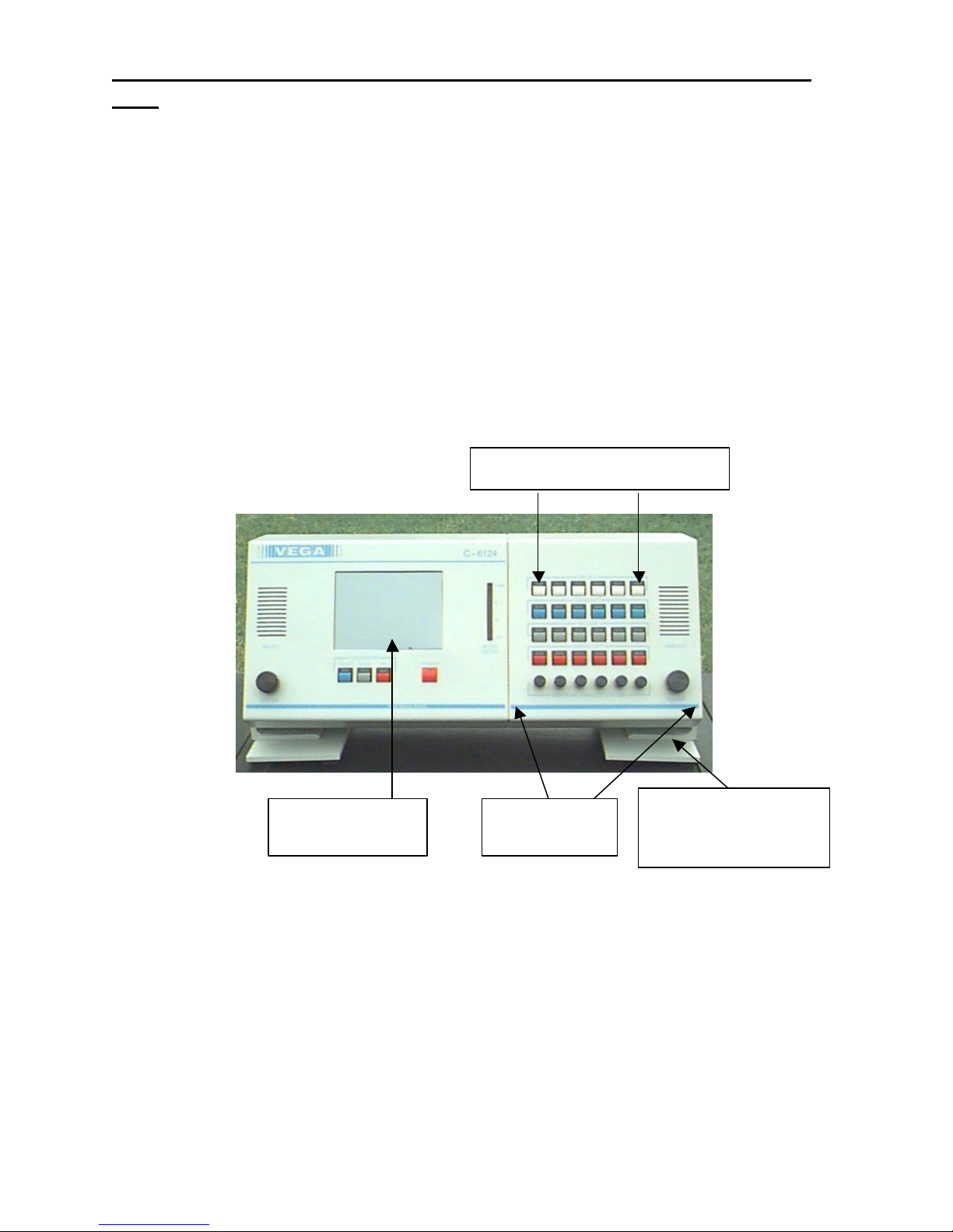
Display
viewing angle
6124
1. Introduction
The model C-6124 is a unique multi -channel, multi-format, and self-contained desktop radio control console.
Choosing one of the following may configure a channel:
TLM - a dedicated two or four wire sequential -tone or E&M relay closure radio control line module.
PLM - a full duplex conventional PSTN telephone or a jumper selectable dial -up access radio control line module.
NOTES: 1- Upon Power-up, no lines are Selected or Unselected. 2 - A module will not function if it has not been
preprogrammed. (Refer to the programming instructions on page 22).
A desk microphone (or gooseneck microphone) may be installed for operation along with a handset (or headset) as
indicated on the back of the UIM module. When a PTT occurs from either of the two microphones, the other will mute
so as not to pick -up unnecessary ambient noise during transmission.
When the handset is taken off hook and a line is Selected, the receive audio from that line is transferred to the
earpiece.
Any combination of line cards may be obtained by simply installing the appropriate card into the desired slot. One to
twenty-four cards may be installed, six for every additional switch panel. All pushbuttons and indicators on the
touchscreen display are under software control and may be customized to look exactly as the user specifies
(customized at factory for additional charge). This flexible approach provides the user full remote contr ol of the
required functions of a two-way radio system while allowing for future expansion or system changes.
Back lit
TLM’s or PLM’S/DLM’S
End Bus Module
(EBM)
Swivel base allows
operator to adjust
The C-6124 sports a backlit LCD touchscreen and a unique enclosure that allows the operator to tilt the console to
the operator's desired viewing angle. This feature allows a more flexible dispatch environment in which the console
may be installed. The dispatcher can easily operate the console while sitting or standing as well as watching the
status of the console from across the room.
Page 8

Remote Control Console 2
2. Hardware Overview
The C-6124 is a multi -line, multi-mode console designed specifically for growth in system requirements. The console
is based on a modular design utilizing multi -processor architecture for maximum flexibility. The system allows for
customization through software and expandability through common hardware.
The console consists of three assemblies.
The User Interface Module (UIM) is the central processor handling the user interface, common controls, touch screen
display, Selected speaker and VU meter, as well as keeping track of the activities of the Selected line.
The Switch Bus Module (SBM) accepts up to six plug-in individual line cards via common audio and data busses. Up
to three SBM’s can be added to the C-6124.
The End Bus Module (EBM) houses the Unselect audio amp and the last six line card slots.
User Interface
Module (UIM)
Switch/Bus
Module (SBM)
End Bus Module
(EBM)
2.1 User Interface Module (UIM)
The UIM consists of the following eight sub-assemblies: power supply, VU meter PCB, crosspatch switch PCB, voice
delay PCB, UIM digital and analog PCB’s, LCD display and touch screen. The central processor is mounted on the
UIM digital PCB. It monitors and controls the activities of the console with respect to the console operator. The
touch screen display is constantly being monitored for activity from the operator while providing instructional
information and feedback. The UIM digital PCB monitors the data bus for line Select while providing PTT, telephone
dialing, and handset hook data to the line cards. All programming functions are accessed through the data bus from
information entered on the touch screen display when in programming mode. All audio is processed on the UIM
analog PCB, this includes TX (microphone), Select and Unselect Speaker and Crosspatch busses. TX audio is
processed and routed to the audio bus while the receive audio is routed to the appropriate speaker power amplifier or
the handset/headset earpiece. The earpiece level is internally adjusted to a comfortable listening level and is not
affected by the speaker volume control. The microphone sensitivity as well as the display contrast may also be
adjusted internally.
2.2 Switch Bus Module (SBM)
The SBM is mounted between the UIM and EBM and is interfaced to the UIM analog PCB through a ribbon cable
connecting the microphone audio, Select audio, Unselect audio, cr osspatch and the data busses together. This entire
bus interface is then branched out to the connectors to which the individual line cards are installed. When a line card
is installed onto the SBM, the four switches, associated indicators and the Unselect volume control for that line
position electrically become part of the line card and are under full control of the card's software. The Unselect
Page 9

3 Vega’s C6124
volume controls can be independently adjusted for a minimum level if desired. Up to six line cards can be instal led on
each SBM.
2.3 End Bus Module (EBM)
The EBM is the last module of the console and houses both the Unselect speaker amplifier and the last six line card
slots.
2.4 Tone Line Module (TLM)
The TLM is a radio control card using either the standard tone control format compatible with Motorola and
Ericsson/GE or E&M relay closure. The line card may be hardware configured for either two-wire or four -wire
operation and may be factory modified to accommodate non-industry standard tone control formats if desired. The
TLM contains a tunable notch filter at the switched transmit audio input, so as not to talk-off the PTT tone when the
microphone is active. This audio is followed by a summing amplifier, where the PTT tone sequence and the DTMF
encoder are added. This combined audio is fed into the line driver amplifier, which drives a balanced interface to the
tone line at the appropriate levels. The receive audio is taken off the balanced tone line, amplified and processed,
then fed into the notch filter, and the DTMF decoder. The line activity detection circuit is branched off at the first
amplifier providing both status signals to the processor as well as a control signal for the line inactivity squelch. The
filtered audio is then switched into either the Selected or monitored audio busses. (Refer to 3.4 page 9 for
functionality).
2.5 Phone Line/Dial-up Modules (PLM/DLM)
The PLM is physically identical to the DLM. The only difference is a jumper position.
The telephone card has identical audio filtering and switching circuits as the TLM except for the interface to the
telephone line. A self-contained hybrid module houses the necessary circuitry to provide TX/RX audio isolation, off
hook enable and ring detect.
The DLM is the dial -up remote card intended to control a remote radio using Vega's Dial-up tone control format
(compatible with Vega Models C-550/RP-250 or RP-251).
The telephone interface is fully FCC and DOC approved. (Refer to 3.5 and 3.6 page 11 & 12 for functionality)
Page 10

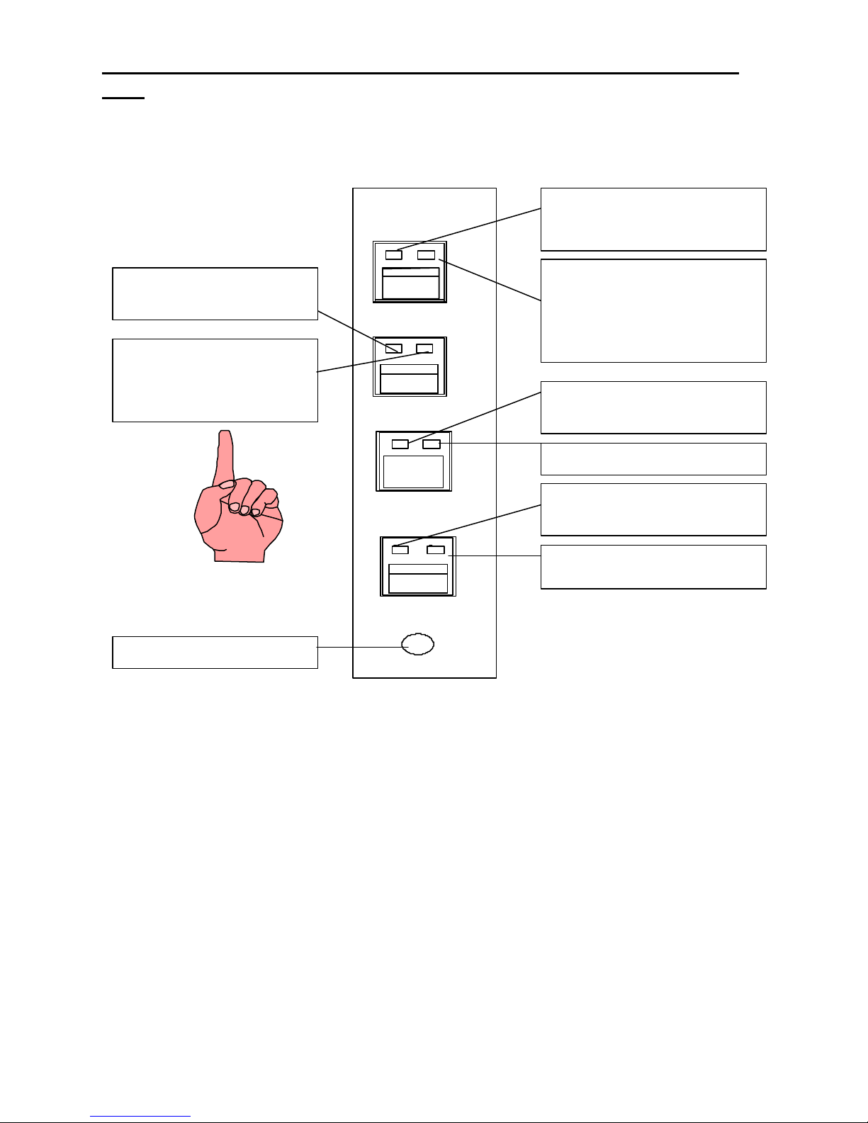
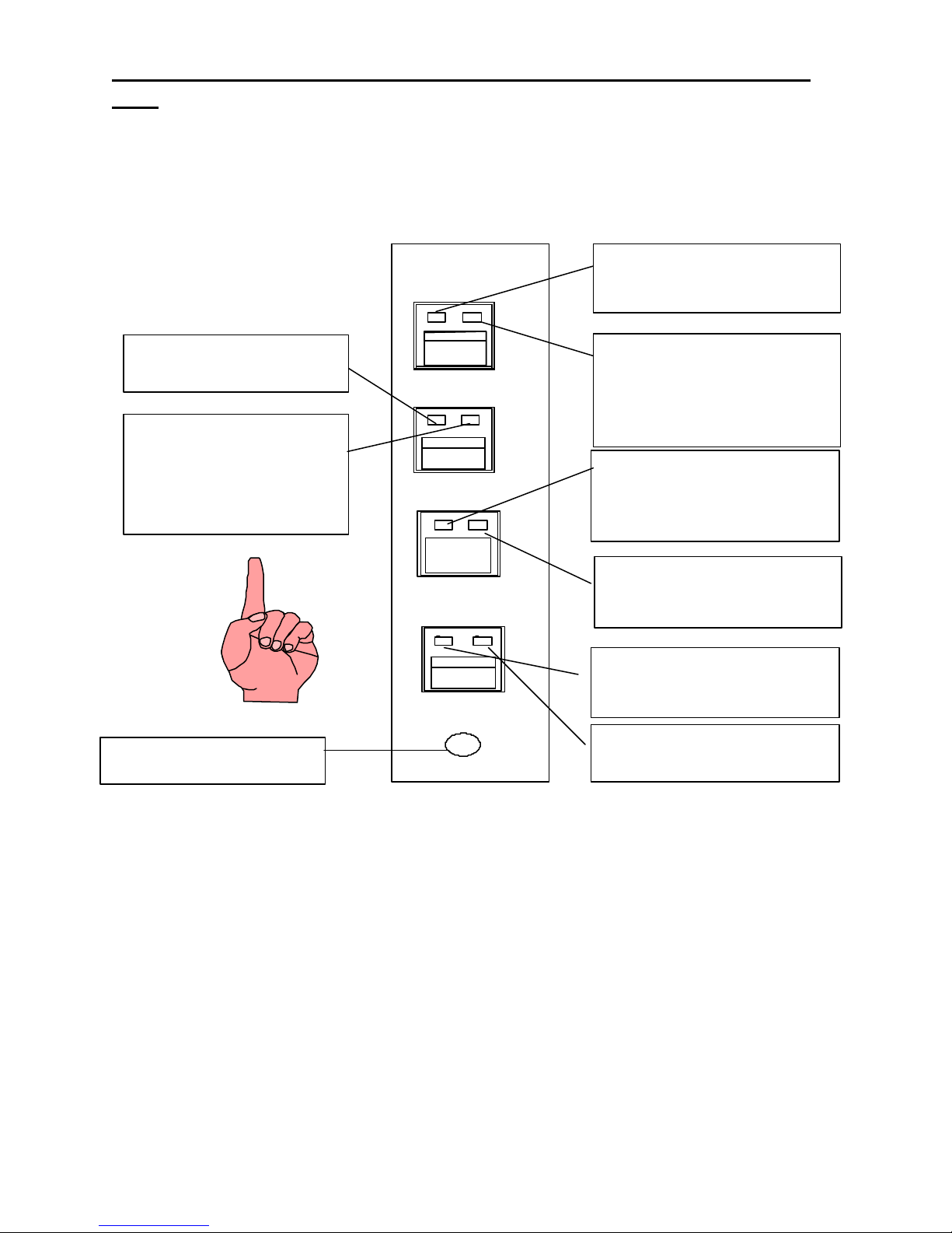
Remote Control Console 4
Screen
Speaker
Meter
Volume Control
Switches
Switch
Swi tches & Indicators
goes here
L1 L2 L3 L4 L5 L6
3. Controls and Indicators
3.1 Fron t Panel
For a description of these controls and indicators please see the following pages.
A self-adhesive label is supplied with each SBM. You can place it above the Select switch pushbuttons. Trim to fit
and print the appropriate information on the strip of paper that slides into the clear plastic holder.
Select
Touch
Audio
Individual Line card
Label holder
Unselect
Speaker
Select
A desk microphone (or gooseneck microphone) may be installed for operation along with a handset (or headset) as
indicated on the back of the UIM module. When a PTT occur s from either of the two microphones, the other will mute
so as not to pick -up unnecessary ambient noise during transmission. Note that, in dual microphone configurations,
the desk microphone is the default microphone. The dedicated PTT button on the handset or headset must be
pressed to use the handset/headset. This is true in all cases except during telephone operation in which the
handset/headset becomes dedicated to the telephone call. In the case of a telephone call, pressing the PTT
bar/button on the handset/headset will place the phone call on hold and transmit microphone audio over the radio.
NOTE: A PLM/DLM (telephone line module/Dial up line module) requires using a telephone headset or a handset for
operation. You cannot operate them if you ar e only using a desk microphone or gooseneck microphone; audio feed
back would occur making conversation unintelligible. They will go off hook, but the RX audio will go nowhere.
Xpatch
PTT
Unselect
Volume Controls
Page 11

5 Vega’s C6124
3.2 Common Controls and Indicators
Select Volume Control: Adjusts the speaker level of the Selected audio. A minimum volume level can be preset on
the speaker card so that the console operator can not turn the volume to zero.
Unselect Volume Control: Adjusts the speaker level of the Unselected audio. A minimum volume level can be preset
on the speaker card so that the console operator can not turn the volume to zero.
Handset, Hookswitch, and PTT: When you pick the handset off the cradle, receive audio from any line is the Select
mode line is transferred to the earpiece and the microphone mouthpiece becomes active. Unselect audio remains on
the Unselect speaker. The exception to this is when a phone call is active. Phone audio will go to the handset
earpiece and Select audio will revert back to the Select speaker until the phone call is done. During the phone call the
operator monitors the Select lines on the Select speaker. If attention must be given to the radio side the operator
need only press the PTT button and microphone audio will be routed to the Select line radios. Releasing the PTT will
transfer microphone audio back to the phone conversation. The phone call is effectively put on hold during radio
transmission and will not be able to monitor the operators radio traffic.
Touchscreen Display: This interface assists the console operator by providing current status of the console and
instructional information. See the following pages for touchscreen examples.
In the operational mode, the liquid crystal display shows the full name of the currently Selected line and associated
function tone. If a line is not Selected, the display will show "no Selection.” If the PTT is pressed without a line
Selected, the console will beep and "no selection" will flash.
The main screen displays soft-key access to such features as Group Select, Simulcast, Timed Mute, Crosspatch,
Frequency selection, CTCSS Monitor, and Intercom. The console operator can also Select any of the 16
preprogrammed telephone numbers as well as manually dialing numbers to access dial -up base stations connected to
the system.
Configuration of the programmable Console features is also done through the touchscreen display. The touchsensitive screen will always beep when touched, providing feedback to the user.
VU Meter: Displays Selected receive and Microphone audio bus levels.
PTT Pushbutton: When pressed all Selected lines will transmit.
Crosspatch Controls:
Select Pushbutton: When Selected and held down you can add any combination of lines to a crosspatch
group by pressing their Select pushbutton.
Block Pushbutton: When pressed will mute the line that is controlling the crosspatch until another line
takes control of the crosspatch group. This is to provide control over excessively long one-sided conversations. To
deselect a line from a crosspatched group, all you need to do is press the release pushbutton on the corresponding
line.
PTT Pushbutton: When pressed this pushbutton transmits console operator microphone audio to all cards
in the crosspatch group.
Page 12

Remote Control Console 6
3.3 Touchscreen Examples
After turning on the console you are greeted by the initial display. Selecting a line will change the "NO SELECTION"
at the bottom of the screen to a description of the line you Selected, for example "MT WILSON F2."
GRPSEL
MONITOR MUTE SIMUL G
DIAL
F1 F3 F4
SEL CH: MT. WILSON F6
RX ALL TX ALL
ALERT INTERCOM
F2
>>>
Figure 3.3a
If function tones F5 through F12 are disabled (via system programming) the ">>>" will not appear. The console will
be limited to four function tones. If F5 through F12 are enabled then the “>>>” will allow the operator to switch to
the F1 through F12 select screen shown in Figure 3.3b.
TRANSMIT FREQUENCY SELECT
F1 F3 F4
F5 F7 F8
F9 F11 F12
<<
F2
F6
F10
SEL CH: MT WILSON F6
Figure 3.3b
Page 13

7 Vega’s C6124
If you wish to dial out, select "DIAL" from the opening screen and the following screen allows you to manually enter
a number to be dialed. The screen will then prompt you to Select a line over which the DTMF will be transmitted.
Press the Select button of the desired line.
A dialed number will appear here
321
CLEAR
RECALL
MEMORY
<< SEL CH: MT. WILSON F2
*
654
987
#0
Figure 3.3c
Should you want to retrieve a number from a preprogrammed memory position, Touch "MEMORY DIAL" for the
following speed dial screen and make your selection from 01 through 16.
MOREMEMORY DIALS
01
SQUAD 56
02
FIRE CAPTAIN
03
MAINTENANCE
04
<<
SEL CH: GROUP SELECT
05
06
07
08
Figure 3.3d
Touch "MORE" for speed dial numbers 9 through 16.
Page 14

Remote Control Console 8
PREVIOUSMEMORY DIALS
09
SQUAD 57
10
POLICE CHIEF
11
AUTO CLUB
12
<<
SEL CH: GROUP SELECT
13
14
15
16
Figure 3.3e
Touch “PREVIOUS” and it will take you back to the first screen (Figure 3.3c)
Page 15

9 Vega’s C-
will light when a parallel
console on the same line is in a PTT
6124
3.4 Tone Line Module (TLM)
Line Select Pushbutton: When one of the line Select pushbuttons is momentarily pressed, that line is Selected and
the previously Selected line is released unless either the Xpatch Select pushbutton or Group Select touchscreen
pushbutton is held down. If the Xpatch pushbutton is held down, any line Selected will be placed into the crosspatch
mode.
When the handset is taken off hook and a line is Selected, the receive audio from that line is transferred to the
earpiece. Upon power -up, none of the lines are Selected or Unselected.
Red LED will light when put in
Unselect monitor mode.
Green LED-is the line activity
indicator and will blink when
you have activity on the RX
circuitry. The green LED will
stay lit if the line is being RX
Blocked.
Unselect
Release
Instant PTT
Volume
Red LED-will blink when a call is
received and will remain steady if
selected.
Green LED-will light when the line
card is placed in an X-patch mode.
It will blink when it is the
controlling card in the X-patch.
Red LED-is lighted when the line is
crossmuted or TX Blocked.
Green LED-
condition.
Red LED-will light when the
individual PTT pushbutton is
pressed or is in the transmit mode.
Green LED-will light when you are
in an intercom mode.
Unselect Volume Control
Line Select Indicators: A red light on the line Select pushbutton will illuminate indicating that the line has been
Selected. A green light will indicate that the line is added to the Xpatch group.
Call Indicator: The red light on each line “select” pushbutton will flash and a audio beep will sound though the
Select speaker indicating a valid DTMF decode has occurred on the line. When the call light illuminates, the line will
auto-monitor for 15 seconds only if the line is not already being monitored or Selected. Selecting the line or taking the
handset off hook will reset the call light and auto-monitor.
Unselect Pushbutton: The Unselect pushbuttons, directly below the Select pushbuttons, operate on a pushon/push-off basis and any combination of lines may be monitored through the Unselected speaker. A red light on
each Unselect pushbutton will illuminate indicating which lines are being monitored.
Line Activity Indicator: A green line activity indicator light on the Unselect pushbutton will flash when line activity
is detected. The light will stay lit if the lines receive audio is being muted as a result of an RX Block.
Release Pushbutton: Releases all functions.
Page 16

Remote Control Console 10
Release Pushbutton Indicators: The red light indicates that the line is crossmuted or is being TX Blocked. A
constant green light indicates that a parallel console is transmitting.
Instant PTT Pushbutton: Located directly below the release pushbutton, when pressed and held, will cause the line
card to generate the required transmit tone sequence. This feature can be engaged at any tim e regardless if the line
has been Selected or not. The red light on the instant PTT pushbutton will illuminate when the channel is keyed by
any PTT command.
Transmit Indicator: A green indicator on the Instant PTT switch will illuminate on the Selected line when in intercom
mode.
Unselect Volume Control: Adjusts the speaker level of the individual monitored audio. A minimum volume level can
be preset internally so that the console operator cannot turn the volume to zero.
Page 17
11 Vega’s C-
monitor and will blink when you
telephone line is off hook.
6124
3.5 Phone Line Module (PLM)
Line Select Pushbutton: A PLM will go off-hook when the select button is pressed. When a PLM line Select
pushbutton is momentarily pressed, that line is Selected and the previously Selected line is put on hold.
Red LED-will light when put in
Unselect monitor mode.
Green LED-is the line activity
have activity on the RX
circuitry.
Unselect
Release
Red LED-will blink when a call is
received or put on hold and will
remain steady if selected.
Green LED-will light when the line
card is placed in an X-patch mode.
It will blink when it is the
controlling card in the X-patch.
Red LED-will only light when press
to release the line.
Green LED-is not used at this time
Instant PTT
Unselect Volume Control
Line Select/call Indicator: A red light on the line Select pushbutton will blink when a call is received, plus an audible
electronic ring is heard in the Unselect speaker. When Selected it will remain on. A green light will indicate that the
line is included in the Xpatch group.
Line-on-hold Indicator: The red light on the Select pushbutton will flash when the line is put on hold. A line is put
on hold by selecting another phone line or by pressing the Select button. When a line on hold is Selected, the hold
indicator will stop flashing and remain on.
Unselect Pushbutton: The Unselect pushbutton directly below the Select pushbutton, operates on a push-on/-off
basis and any combination of lines may be monitored through the front speaker. A red light on each Unselect
pushbutton will illuminate indicating which lines are being monitored.
Line Activity Indicator: A green line activity light on the Unselect pushbutton will flash if the line is being
monitored or has been Selected and line activity is detected.
Volume
Red LED-is not used and should
not illuminate when depressed.
Green LED-will light when the
Release Pushbutton: Directly below the Unselect pushbutton is the release pushbutton. When pressed for two
seconds an on-hook condition is generated and the call is terminated, and the line will reset. The red light on the
pushbutton will illuminate while the pushbutton is pressed.
Instant PTT Pushbutton: The red light will not illuminate if the PTT pushbutton is pressed, the green light will
provide a visual indication that the line is off hook.
Unselect Volume Control: Adjusts the speaker level of the individual monitored audio.
Page 18

Remote Control Console 12
Page 19
13 Vega’s C-
monitor and will blink when you
button is pressed to release the line
6124
3.6 Dial-up Line Module (DLM)
Line Select Pushbutton: Line Select can only occur if a telephone number is Selected from either the preset number
menu, entered manually or if the line is on hold. When a DLM line Select pushbutton is momentarily pressed, that line
is Selected and the previously Selected line is put on hold. When the handset is taken off hook, the receive audio
from that line will no longer be present at the speaker but transferred to the earpiece.
Red LED-will blink when a call is
received or put on hold and will
remain steady if selected.
Red LED-will light when put in
Unselect monitor mode.
Green LED-is the line activity
have activity on the RX
circuitry. It will stay lit if the
DLM is being RX Blocked.
Unselect Volume Control
Unselect
Release
Instant PTT
Volume
Green LED-will light when the line
card is placed in an X-patch mode.
It will blink when it is the
controlling card in the X-patch.
Red L ED-will light when the release
or the line is crossmuted/ TX
Blocked.
Green LED-will light when a
paralleled console is in a PTT
condition.
Red LED-will light when the
individual PTT pushbutton is
pressed.
Green LED-will light when a parallel
console is off hook.
Line Select Indicator: A red light on the line Select pushbutton will blink when a call is received, plus an audible
alert is heard in the Unselect speaker. When Selected it will remain on. A green light will indicate that the line is
Selected into the Xpatch group.
Line-on-hold Indicator: The red light on the Select pushbutton will flash when the line is put on hold. A line is
automatically put on hold by Selecting another line. When a line on hold is Selected, the hold indicator will stop
flashing and remain on.
Call Indicator: When a dial access line rings, the red light on the line Select pushbutton will flash indicating an
incoming call from a mobile and you will hear an audible electronic ring in the Unselect speaker. To answer an
incoming call, select the ringing line by pressing the pushbutton. This light will also indicate the line is in use and is
unavailable for dialing to a base station.
Unselect Pushbutton: The Unselect pushbutton, directly below the Select pushbutton, operates on a push-on/-off
basis and any combination of lines may be monitored through the front speaker. A red light on each Unselect
pushbutton will illuminate indicating which lines are being monitored or the line is crossmuted/TX Blocked.
Line Activity Indicator: A green line activity light on the Unselect pushbutton will flash if the line is off hook and
line activity is detected. The light will stay lit if the line is being RX Blocked.
Page 20

Remote Control Console 14
Release Pushbutton: Directly below the Unselect pushbutton is the release pushbutton. Pressing this pushbutton
for two seconds will send a double monitor burst to the radio control panel (RP250 or RP251) terminate the call by
disconnecting the line from the central office. The red light on the pushbutton will illuminate while the pushbutton is
pressed. The red light will light when the line is being TX Blocked.
Instant PTT Pushbutton: Located directly below the release pushbutton, when pressed and held, will cause the line
card to generate the required PTT tone sequence. The red light on the instant PTT pushbutton will illuminate while
the pushbutton is pressed.
Unselect Volume Control: Adjusts the speaker level of the individual Unselect audio.
Page 21
15 Vega’s C6124
4. Functional Description
4.1 Touchscreen
The following pages describe the various touchscreen menus and their functions available on the C-6124. Upon
turning the power on the console will boot-up in the main menu and you are greeted by the initial display. (Figure
4.1).
GRPSEL
MONITOR MUTE SIMUL G
DIAL
F1 F3 F4
SEL CH: MT. WILSON F6
Figure 4.1 Main Menu
GRPSEL/XPATCH:
This button may be changed in the programming mode to be either a toggle on/off group select button or a
preprogrammed crosspatch group select button. The change is done in the CROSSPATCH GROUP SELECT screen
found in section 5.1.6 of the programming section of the manual.
RX ALL TX ALL
ALERT INTERCOM
F2
>>>
The GRPSEL button is a toggle ON/OFF button which disables the 1ofN functionality of the console. When
the GRPSEL button is illuminated the operator is able to set up a Simul -group of as many cards as is desired. To
activate the Group Select mode the operator presses the GRPSEL button. The button will illuminate. As long as the
button is illuminated the operator may add or delete lines to the group. Dial -up lines must have an active call to be
included in a group. When the operator is finished setting up the Sim ul-group the operator presses the GRPSEL
button again to revert back to the 1ofN mode.
The lines are allowed in a group are restricted by the TX Block settings set in System programming mode. In
the example where line 1 blocks lines 2 and 3 the operator m ay include 2 and 3 in the group only if line 1 is not part of
the group. If line 1 is included in the group the console will not allow lines 2 and 3 to be added. If line 2 or 3 are
already in the group when line 1 is Selected line 1 will be included in the group, but lines 2 and 3 will drop out.
The XPATCH button will transfer the user to a preprogrammed crosspatch group select screen. From this screen one
of eight preprogrammed groups may be selected.
Page 22

Remote Control Console 16
XPATCH GROUP SELECT
01
SQUAD 56
02
FIRE CAPTAIN
03
MAINTENANCE
04
<<
SEL CH: MT. WILSON
05
06
07
08
Figure 4.2 Xpatch Group Select
RX ALL (Receive All): Push to monitor all lines that are not in the Select mode. Any line that is in the Select mode
will automatically become part of the Unselect group when it is taken out of Select mode.
TX ALL (Transmit All) : This feature gives the user a convenient means of Selecting all lines for Simul-transmissions
without having to group select one at a time. As in group select, if a dial -up line is to be included in this feature, the
line must already be dialed-up.
To initiate Simulcast, momentarily touch the "TX ALL" on the display. The line description will change to "Group
Select Mode", and all available lines will automatically be Selected.
To disengage Simulcast, simply Select a single line in the usual manner.
The TX ALL function will not include any line which TX Blocks any other line. For example, If line 1 TX Blocks lines
2 and 3 a TX ALL command will include lines 2 and 3, but not line 1 (assuming lines 2 and 3 do not TX Block any
other card.
CTCSS MONITOR: When touched momentarily, this featur e causes the Selected base station with a CTCSS
decoder to momentarily unmute so that the dispatcher may monitor for activity on the air.
This reduces the possibility of accidentally interfering with other users on the channel who may be using a different
CTCSS tone. This capability is required by FCC regulations.
TIMED MUTE : When touched, TIMED MUTE mutes all "Unselected" audio for fifteen seconds. This feature is
useful when the dispatcher wishes to concentrate on the Selected channel without interference from the other lines.
The mute time is programmable up to 59 seconds. The programming is done in the System programming menu
Page 23

17 Vega’s C6124
SIMUL GROUP: The group select key allows the user to Select multiple lines for simultaneous transmissions. If dial -
up lines are to be included in the group select, they must first be dialed-up and on hold.
To engage group select, press SIMUL GROUP on the display, this takes you to another screen (Figure 4.3). To
initiate one of the preprogrammed groups, simply press the corresponding number on the screen. To manually Select
a group, press and hold the manual select button and then Select each line for the group setup.
The lines allowed in a group are restricted by the TX Block settings set in System programming mode. In
the example where line 1 blocks lines 2 and 3 the operator may include 2 and 3 in the group only if line 1 is not part of
the group. If line 1 is included in the group the console will not allow lines 2 and 3 to be added. If lines 2 or 3 are
already in the group when line 1 is Selected line 1 will be included in the group, but lines 2 and 3 will drop out.
SIMUL GROUP SELECT
MANUAL
01
SQUAD 56
02
FIRE CAPTAIN
03
MAINTENANCE
04
<<
SEL CH: MT. WILSON
05
06
07
08
Figure 4.3
To disengage group select, simply Select a line in the usual manner.
If more lines are to be added to a previously Selected group, car ry through as before, touch and hold and Select the
desired lines. The line description will change to "Group Select Mode" when this feature is engaged.
To deselect a line from the group selected simply press the release pushbutton on the desired line.
Page 24

Remote Control Console 18
DIAL: This function is the doorway into the DTMF dialing screen. When touched, the display changes to the
manual dial keypad screen (Figure 4.4). Here the user can generate DTMF over the air on tone lines or manually dial a
phone number for the DLM or PLM lines.
A dialed number will appear here
CLEAR
RECALL
MEMORY
<< SEL CH: MT. WILSON F2
*
Figure 4.4 Manual Dial Keypad Screen
321
654
987
#0
If you are dialing a mobile selective calling address, you first must enter the number and then Select the appropriate
TLM. Even if the TLM is currently in the Select mode you must reselect it to ini tiate the tone sequence.
When manually dialing a phone number, you must first dial the number and then Select the PLM. Upon Selecting the
PLM, the line is seized and the dialed phone number is sent out.
On the Manual Dial Screen, pushing “<<” returns the display back to the main menu, pressing memory dial brings up
the Speed-Dial Screen (Figure 45) for calling any one of sixteen preset numbers on either a DLM or PLM line. In the
Speed-Dial Screen, touching “<<” toggles the user back to the manual dial scr een (Figure 4.4). Touching “MORE”
brings up the next speed dial screen (speed dial presets 09 through 16) as shown in (Figure 4.6).
Page 25

19 Vega’s C6124
MOREMEMORY DIALS
01
POLICE CHIEF
02
MAYORS OFFICE
03
COMMISSIONER
04
<<
SEL CH: GROUP SELECT
05
06
07
08
Figure 4.5 Speed-Dial Menu
09
SWAT TEAM
13
PREVIOUSMEMORY DIALS
10
GAS COMPANY
11
ELECTRICAL DEPT
12
<<
SEL CH: GROUP SELECT
14
15
16
Figure 4.6 Speed-Dial Menu
Pressing “<<” will take you back to the manual dial screen. Pressing “PREVIOUS” will take you back to the first
memory dial screen 01-08.
INTERCOM: When touched and held, this feature will remove all control tones from a Selected dedicated tone line to
allow the operator to talk to another console on the network without keying the associated transmitter. This intercom
soft key is used in place of the PTT pushbuttons. For this feature to work the communicating consoles must not have
the Crossmute function enabled. (Refer to the Crossmute programming section for the TLM).
Page 26

Remote Control Console 20
ALERT: When touched and held, will enable the PTT on the Selected line or lines and transmit a 1000Hz alert tone,
until released. If the Selected cards are not in the transmit mode when the Alert button is pressed the C-6124 will key
up those cards and then send the 1000Hz tone
TRANSMIT FREQUENCY SELECT
F1 F3 F4
F5 F7 F8
F9 F11 F12
<<
F2
F6
F10
SEL CH: MT WILSON F6
Figure 4.7 Function Tone Select Menu
F1 to F4, F5 to F12: When any one of the function keys are momentarily touched, its function tone sequence will be
generated on the Selected line. This will also engage the Selected line to generate that function tone during
subsequent PTT's. The console will remember the function tones for all the lines, as they are assigned, and will be
displayed accordingly.
“>>>”: Displays all available function tones, F1 through F12 (Figure 4.7). Thi s icon does not appear if F5 through F12
are disabled in the system programming (Refer to the System programming section for programming Function Tone
Parameters).
“<<”: Takes you back to the main menu.
4.2 Tone Lines (TLM)
Selecting a Line: When the desired line Select pushbutton is momentarily pressed, the receive audio from this
Selected line is placed on the speaker and the previously Selected line is disengaged. The currently Selected line
name (programmable) is displayed on the screen and the line Select indicator is illuminated.
If the handset is taken off hook, the receive audio is transferred to the handset earpiece.
Monitoring (Unselecting) a Line: To monitor a line, press the Unselect pushbutton momentarily. The receive audio
from the monitor ed line will be heard on the consoles Unselect speaker (and can be adjusted by the line volume
control). The red light on the Unselect pushbutton will also illuminate to indicate a monitored condition.
To disengage the Unselect function, once again momentarily press the Unselect pushbutton. The red light on the
Unselect pushbutton will go out indicating the line is not being monitored.
The Unselect function is independent of the other lines and can be engaged and disengaged regardless of the status
of the other lines allowing any combination of lines to be monitored simultaneously. Upon power -up, all lines will be
muted until either engaging the Unselect pushbutton, engaging the line Select pushbutton, or by a valid DTMF
decode for each line.
DTMF Decoder: When a four digit DTMF code is sent from a mobile to the console, the code is decoded, the Select
switch's Red LED lights, and the console starts monitoring that line. The line will be monitored for 15 seconds. The
call light will stay on until the call is answered by the operator (base station Selected).
Releasing a Line: To release a line, simply press the release pushbutton for that line.
Page 27

21 Vega’s C6124
Instant PTT: To generate a PTT tone sequence whether the line is Selected or not, simply press the desired line’s
instant PTT pushbutton.
4.3 Phone Line and Dial-up Line Modules (PLM/DLM)
Dialing from Preset Memory: Bring up the speed dial menu by pressing DIAL on the main menu. Scroll through the
preset telephone numbers by touching MEMORY DIAL and MORE or PREVIOUS at the top of the screen.
PREVIOUSMEMORY DIALS
09
SWAT TEAM
10
GAS COMPANY
11
ELECTRICAL DEPT
12
<<
SEL CH: GROUP SELECT
13
14
15
16
Figure 4.8 Speed Dial Menu
When the desired base station alphanumeric description appears on the screen, touch the display anywhere on the
station description. The screen will then display the chosen telephone number and prompt you to PLEASE SELECT
LINE.
At the prompt, Select the dial access line you wish to dial out on by momentarily pressing the line Select pushbutton.
When the operator Selects a valid dial -up line, the red light on the line Select pushbutton should light indicating a
Selected line and the display will momentarily display "Please wait" while the dialing information is being transferred
to the line card.
The dialing speed is adjusted to accommodate an in-house system where a second dial tone must be acquired.
Therefore, the first digit dialed will have a one-second pause after it, while the rest of the digits will be dialed at a rate
of 10 digits per second. The station description in the preprogrammed number list will now become the base station
name whenever the line is Selected, just like a tone line.
Manually Dialing Numbers: A secondary screen is available to manually dial a telephone number via a familiar
TouchTone ™ keypad. To access the keypad, touch DIAL on the main menu. The console assumes the store and
forward method of manually dialing a number. Therefore, the number to be dialed must first be entered before any
dialing will occur. A maximum of sixteen numbers may be entered. To manually dial a number, touch the telephone
number as if dialing the number on a regular phone. The touched numbers will be displayed on the left side of the
keypad as they are entered. The display will then prompt the user to PLEASE SELECT A LINE. At the prompt, Select
the desired dial access line you wish to dial out on by momentarily pressing the line Select pushbutton. The console
will then speed-dial the entered number similar to a memory dial. As in auto dialing, both on and off hook dialing is
permitted. The dialing speed is adjusted to accommodate an in-house system wher e a second dial tone must be
acquired, much like a memory dial. The number manually dialed will now become the name of the base station
whenever the line is Selected.
Page 28

Remote Control Console 22
Answering a Ringing Line: When one of the dial -up lines ring, the operator will hear the ring tones in the speaker
and the call indicator will flash. To answer an incoming call, momentarily press the line Select pushbutton on the
ringing line with the handset off hook.
Putting a Line on Hold: To put an active dial -up line on hold, Select another line; either another dial-up line or a tone
line. When a dial -up line is put on hold, the line select indicator of that line will flash indicating the hold status. A
dial-up line can be placed on hold regardless if the call was initiated by dialing a number or by answering a ringing
line. To take the line off hold, simply Select that line. A paralleled console can pick up any line on hold or join in on
the conversation, by simply Selecting the line.
Terminating a Call: The console operator can terminate the line by pressing the release pushbutton for 2 seconds.
The release pushbutton will terminate the call regardless of the status of the line. This is useful when there are more
than one dial -up lines active simultaneously.
In the case of a DLM line, a double monitor burst will be sent up the line to reset the RP-250/ RP251 panel prior to
disconnect.
Answering a TLM while talking on the PLM/DLM Line: Pressing the PTT switch during a telephone conversation
will cause the transmit audio to transfer to a Selected TLM module. You can answer a call on a TLM module simply
by pressing the PTT switch on the handset or headset if the line has been Selected. If the line has not been Selected,
all you have to do is Select the line and press the PTT switch. You can also use the TLM’s instant PTT switch with
the line Selected or Unselected. Upon completing the call on the TLM, you can easily revert back to the telephone
conversation by releasing the PTT switch.
Instant PTT: This function is not applicable to the PLM line. A DLM Module will generate a PTT sequence to the
RP250/RP251 control station panel.
4.4 Crosspatch Operation
Putting Lines into Crosspatch mode: Press and hold the crosspatch select button, now select the desired lines and
the green LED will illuminate as cards are selected. When finished selecting the crosspatch group, release the
crosspatch select button.
Talking on a crosspatch group: To talk on a crosspatch group press Crosspatch PTT and talk into the mic as normal.
Generating a Phone patch: To generate a phone patch the phone line must first be connected, then connect into
crosspatch mode as normal.
To disengage a crosspatch group: To disengage a crosspatch group, double click the crosspatch select button.
Page 29

23 Vega’s C6124
5. PROGRAMMING THE C-6124 SYSTEM
The C-6124 is placed in programming mode by moving a jumper on the UIM analog board. The following
procedure acts as a guide to enter the programming mode:
Definitions:
UIM - User Interface Module. This is the housing which holds the touchscreen
UIM Anal og board – The circuit board assembly mounted to the bottom of the UIM (Refer to UIM parts locator).
Enter the programming mode:
1) Flip C-6124 power switch to the OFF position
2) Remove any microphone and all plug-in terminal blocks from the rear of the UIM housing.
3) Unscrew the two screws in the upper left and upper right hand corners of the rear of the UIM housing.
4) Carefully remove the back panel. Be careful of the wiring that is attached to the power supply, which is
mounted to the back panel. All wiring must be kept connected so lay the back panel close to the UIM
housing.
5) Flip the C-6124 power switch to the ON position.
6) Move jumper JP5 on the UIM analog board to the B position. JP5 is directly behind the three position plugin terminal block, between a large capacitor and a ribbon cable connector. The B position has the text
“PROG” written by it.
6) The C-6124 will power up in programming mode.
Saving the programmed features into all line cards:
1) Press the SAVE PROGRAMMING INFORMATION icon on the main system screen
2) Wait for the programming system finished message
Getting out of programming mode:
1) Move JP5 to the A position
2) Flip C-6124 power switch to the OFF position.
3) Carefully replace the back panel. Be watchful that no cable is unduly stressed. The back panel is installed
by sliding the teeth on the bottom of the panel into the slots on the bottom of the UIM housing. Make sure
no cables are being pinched as the top of the back panel is brought up to close the housing.
4) Replace the two screws at the upper left and right hand sides of the housing.
5) Replace microphone and plug-in terminal blocks.
6) Flip the C-6124 power switch to the ON position. The C-6124 will power up into the Operational mode.
Page 30

Remote Control Console 24
--
02 03
5.1 Programming at the system level àà PARAMETER EXPLANATION
SYSTEM PROGRAMMING
OPTION MENU 1
01
EDIT MEMORY DIALS
EDIT SIMUL GROUP NAMES
EDIT CROSSPATCH GROUP NAMES
04
OPTION MENU 2
SAVE PROGRAMMING INFORMATION
LINE
OPTION MENU 2
SIMUL GROUP SELECT
05
CROSSPATCH GROUP SELECT
06
07
OTHER PARAMETERS
08
OPTION MENU 3
LINESYSTEM PROGRAMMING
OPTION MENU 3
FUNCTION TONE PARAMETERS
09
RX BLOCK GROUPS
10
11
TX BLOCK GROUPS
12
OPTION MENU 1
SYSTEM PROGRAMMING MENU 1 SYSTEM PROGRAMMING MENU 2 SYSTEM PROGRAMMING
MENU 3
When programming mode is entered the first screen presented is the SYSTEM PROGRAMMING MENU 1.
Three System Programming Menus are available and may be reached by scrolling through the OPTION MENU
buttons.
01 EDIT MEMORY DIALS:
The C-6124 contains memory space for sixteen memory dials. Each memory dial may contain up to 16 DTMF
characters from 0-9,#, and *. The memory dial entries may be used for phone numbers or any other DTMF signaling
usage. Each memory dial entry also has a corresponding 12 character alphanumeric that the user programs in to label
the memory dial.
02 EDIT SIMUL GROUP NAMES:
The C-6124 has a group select function where more than one line card may be in the Select mode at one time.
Eight preprogrammed groups may be stored in the C-6124 memory. This button allows each entry’s 12 character
alphanumeric label to be entered. The selection of the lines to be included in the group is done on
MENU 2.
03 EDIT CROSSPATCH GROUP NAMES:
The C-6124 has a crosspatch group select function where more than one line card may be crosspatched with
one button stroke. Eight preprogrammed groups may be stored in the C-6124 m emory. This button allows each
entry’s 12 character alphanumeric label to be entered. The selection of the lines to be included in the crosspatch
group is done on MENU 2.
04 OPTION MENU 2:
Pressing this button brings up MENU 2 of the SYSTEM PROGRAMMING.
--
SAVE PROGRAMMING INFORMATION:
Pressing this button will program all current system parameters into all line cards, used when changing one
line card or to verfy that all line cards are programmed the same.
05 SIMUL GROUP SELECT:
This options allows the selection of the lines which will be part of each simultaneous Select group.
06 CROSSPATCH GROUP SELECT
This options allows the selection of the lines which will be part of each preprogrammed crosspatch group.
07 OTHER PARAMETERS:
Pressing this button allows Mute time duration to be changed and parallel crosspatch signaling to be
enabled or disabled.
08 OPTION MENU 3:
Scrolls to OPTION MENU 3.
LINESYSTEM PROGRAMMING
Page 31

25 Vega’s C6124
09 FUNCTION TONE PARAMETERS:
Pressing this button will allow function tone parameters to be programmed. In the Function Tone
characteristic programming screen the C-6124 may be programmed for four or twelve function tone operation and the
frequencies of F3 and F4 may be changed to an alternative frequency format.
10 RX BLOCK
This allows each card to be an RX Blocker. This means that the assigned lines will mute their receive audio
when the blocker is in the transmit mode. For example, if line 1 blocks 2 and 3 then lines 2 and 3 will mute their receive
audio whenever line 1 is in a transmit condition.
11 TX BLOCK
This allows each card to have a group of other lines which are not allowed to be in the Select mode with it.
For example, if line 4 TX Blocks lines 6 and 7 the C-6124 will not allow line 4 to be in a simul -group with either 6 and 7.
12 OPTION MENU 1:
Pressing this button returns to MENU 1 of SYSTEM PROGRAMMING.
Page 32

Remote Control Console 26
04
02
03
EDIT SIMUL GROUP NAMES
OPTION MENU 2
EDIT X[ATCJ GROUP NAMES
5.1.1 Programming at the system level àà MEMORY DIAL NAME EDITING
SYSTEM PROGRAMMING
OPTION MENU 1
01
EDIT MEMORY DIALS
EDIT XPATCH GROUP NAMES
SAVE PROGRAMMING INFORMATION
--
LINE
01
SQUAD 56
02
FIRE CAPTAIN
03
MAINTENANCE
04
<<
05
06
07
08
SYSTEM PROGRAMMING MENU 1 MEMORY DIAL SELECTION
From MENU 1 press the 01 button. This will bring up the MEMORY DIAL SELECTION
menu. Select the number of the memory dial to be programmed.
MEMORY DIAL SELECTION button definition
01 - 08 Brings up the NAME/NUMBER screen for parameter programming.
MORE This button brings up memory dial spaces 09 through 16.
<< This button returns to MENU 1.
SYSTEMEDIT MEMORY DIALS
1 2 3 4 5 6 7 8 9 0
S Q U A D 5 6
MOREEDIT MEMORY DIALS
01
EDIT NAME SQUAD 56
02
EDIT NUMBER 13165556309
<<
Q W E R T Y U I O P
A S D F G H J K L ,
Z X C V B N M - . :
SAVE
←
→<< SAVE SPACE
NAME/NUMBER screen ALPHANUMERIC KEYPAD
Selecting a memory number from the MEMORY DIAL SELECTION screen will bring up the
NAME/NUMBER screen. From this screen the alphanumeric name or the number to be dialed may be programmed.
NAME/NUMBER screen button definition:
SYSTEM ------ Pressing this button returns the C-6124 to MENU 1
01 ---------------- Pressing this button brings up the ALPHANUMERIC KEYPAD for name programming.
02 ---------------- Pressing this button accessess the NUMERIC KEYPAD for dial number programming.
<< --------------- Pressing this button returns the C-6124 to the MEMORY DIAL SELECTION screen
ALPHANUMERIC KEYPAD screen button definition:
When 01 is pressed on the NAME/NUMBER screen the ALPHANUMERIC KEYPAD will appear. The
assigned name will appear at the top of the screen. If no name has been assigned the top of the screen will contain 12
blocks. A name may consist of up to 12 characters from the keyboar d.
<< This button aborts the name programming operation and brings back the menu.
SYSTEM PROGRAMMING
SAVE This button saves the displayed entry.
OPTION MENU 1
ßß This button moves the cursor one space to the left with no change to the name.
01
EDIT MEMORY DIALS
SPACE This button provides a blank in the name.
àà This button moves the cursor one space to the right with no change to the name.
02
EDIT SIMUL GROUP NAMES
LINE
01
02
SQUAD 56
FIRE CAPTAIN
MOREEDIT MEMORY DIALS
05
06
03
03
5.1.2 Programming at the system level àà MEMORY DIAL NUMBER EDITING
04
OPTION MENU 2
MAINTENANCE
04
07
08
Page 33

27 Vega’s C6124
SYSTEM PROGRAMMING MENU 1 MEMORY DIAL SELECTION
From MENU 1 press the 01 button. This will bring up the MEMORY DIAL SELECTION
menu. Select the number of the memory dial to be programmed.
MEMORY DIAL SELECTION button definition
01 - 08 Brings up the NAME/NUMBER screen for parameter programming.
MORE This button brings up memory dial spaces 09 through 16.
<< This button returns to MENU 1.
EDIT NUMBER
13165556309
CLEAR
RECALL LAST
SAVE
<<
321
654
987
#0*
01
EDIT NAME SQUAD 56
02
EDIT NUMBER 13165556309
<<
SYSTEMEDIT MEMORY DIALS
NAME/NUMBER SCREEN NUMERIC KEYPAD
When 02 on the NAME/NUMBER screen is pressed the NUMERIC KEYPAD will appear with the assigned
number (if any) appearing. Up to 16 digits may be programmed for each memory dial.
NUMERIC KEYPAD button definition:
1 - # Pressing these buttons creates the number to be saved.
CLEAR Pressing this button will clear the entry without saving.
RECALL LAST Pressing this button will recall the last saved entry.
SAVE Pressing this button will save the entry and return the C-6124 to the NAME/NUMBER
screen.
<< Pressing this button returns the C-6124 to the NAME/NUMBER screen.
Page 34

Remote Control Console 28
5.1.3 Programming at the system level àà SIMULCAST GROUP NAME EDITING
SYSTEM PROGRAMMING
OPTION MENU 1
01
EDIT MEMORY DIALS
02
EDIT SIMUL GROUP NAMES
03
EDIT CROSSPATCH GROUP NAMES
04
OPTION MENU 2
LINE
EDIT SIMUL GROUP NAMES
C O M M A N D
01
02
03
04
<<
05
06
07
08
SYSTEM PROGRAMMING MENU 1 GROUP NAME ASSIGNMENT
The C-6124 allows eight preprogrammed simulcast group names. Each of these groups may have up to a 12
character alphanumeric name to identify it. To program the names press 02 on the MENU 1 screen. This will bring
up the GROUP NAME ASSIGNMENT screen. From this screen select the number of the group that is to be
programmed. Unprogrammed names show up as blocks. Note: A simulcast group programmed with the desired lines
(described later) does not need a programmed name to fucntion. Pressing the << button will return the C-6124 to
MENU 1.
C O M M A N D
1 2 3 4 5 6 7 8 9 0
Q W E R T Y U I O P
A S D F G H J K L ,
Z X C V B N M - . :
SAVE
←
→<< SAVE SPACE
ALPHANUMERIC KEYPAD
ALPHANUMERIC KEYPAD screen button definition:
When one of the eight group numbers from the GROUP NAME ASSIGNEMNT screen is pressed the
ALPHANUMERIC KEYPAD will appear. The assigned name will appear at the top of the screen. If no name has
been assigned the top of the screen will contain 12 blocks. A name may consist of up to 12 characters from the
keyboard.
<< This button aborts the name programming operation and brings back the GROUP NAME ASSIGNMENT
screen.
SAVE This button saves the displayed name and returns to the GROUP NAME ASSIGNMENT screen.
ßß This button moves the cursor one space to the left with no change to the name.
SPACE This button provides a blank in the name.
àà This button moves the cursor one space to the right with no change to the name.
Page 35

29 Vega’s C6124
5.1.4 Programming at the system level àà CROSSPATCH GROUP NAME
EDITING
SYSTEM PROGRAMMING
OPTION MENU 1
01
EDIT MEMORY DIALS
02
EDIT SIMUL GROUP NAMES
03
EDIT CROSSPATCH GROUP NAMES
04
OPTION MENU 2
LINE
EDIT CROSSPATCH GROUP NAMES
C O M M A N D
01
02
03
04
<<
05
06
07
08
SYSTEM PROGRAMMING MENU 1 CROSSPATCH NAME ASSIGNMENT
The C-6124 allows eight preprogrammed crosspatch group names. Each of these groups may have up to a
12 character alphanumeric name to identify it. To program the names press 03 on the MENU 1 screen. This will
bring up the CROSSPATCH NAME ASSIGNMENT screen. From this screen select the number of the group that is
to be programmed. Unprogrammed names show up as blocks. Note: A crosspatch group programmed with the
desired lines (described later) does not need a programmed name to function. Pressing the << button will return the
C-6124 to MENU 1.
C O M M A N D
1 2 3 4 5 6 7 8 9 0
Q W E R T Y U I O P
A S D F G H J K L ,
Z X C V B N M - . :
<< SAVE SPACE←
SAVE
→
ALPHANUMERIC KEYPAD
ALPHANUMERIC KEYPAD screen button definition:
When one of the eight group numbers from the CROSSPATCH NAME ASSIGNMENT screen is pressed the
ALPHANUMERIC KEYPAD will appear. The assigned name will appear at the top of the screen. If no name has
been assigned the top of the screen will contain 12 blocks. A name may consist of up to 12 characters from the
keyboard.
<< This button aborts the name programming operation and brings back the XPATCH NAME ASSIGNMENT
screen.
SAVE This button saves the displayed name and returns to the XPATCH NAME ASSIGNMENT screen.
ßß This button moves the cursor one space to the left with no change to the name.
SPACE This button provides a blank in the name.
àà This button moves the cursor one space to the right with no change to the name.
Page 36

Remote Control Console 30
5.1.5 Programming at the system level àà SIMULCAST GROUP ASSIGNMENT
SYSTEM PROGRAMMING
OPTION MENU 1
01
EDIT MEMORY DIALS
02
EDIT SIMUL GROUP NAMES
03
EDIT CROSSPATCH GROUP NAMES
04
OPTION MENU 2
LINE
OPTION MENU 2
SIMUL GROUP SELECT
05
CROSSPATCH GROUP SELECT
06
07
OTHER PARAMETERS
08
OPTION MENU 3
LINESYSTEM PROGRAMMING
SYSTEM PROGRAMMING MENU 1 SYSTEM PROGRAMMING MENU 2
SIMUL GROUP SELECT
C O M M A N D
01
02
03
04
<<
05
06
07
08
1 2 3 4 5 6
1
7 8 9 10 11 12
8
13 14 15 16 17 18
19 20 21 22 23 24
<< SAVE
SIMUL GROUP SELECT 1
5
SIMULCAST GROUP SELECT SIMULCAST GROUP PROGRAMMING
To program the lines which are part of a simulcast group select OPTION MENU 2 from the MENU screen. The
MENU 2 screen will appear. Press the SIMUL GROUP SELECT selection to continue on to program the simulcast
group.
In the SIMULCAST GROUP SELECT screen the eight group names are displayed. Groups which have not
had their names programmed appear as blocks. To program an entry press the group number you would like to
program. The SIMULCAST GROUP PROGRAMMING screen shown above represents what would appear on the
screen if 01 is selected from the SIMULCAST GROUP SELECT screen. To add lines IDs to the simulcast group
press on the corresponding number on the screen. The number will invert. To drop a line ID off the group pressed
the inverted ID number and it will drop out of the group. In the example screen above line IDs 1, 5 and 8 are part of
the simulcast group. When the configuration is as is desired press the SAVE button.
When programming is complete press the << button to return to MENU 2. It is suggested that all TX
Blocks be setup before the simulcast groups are set up. When a TX Block is set up the C-6124 will edit simulcast
groups to drop out violations. When programming simulcast groups the C-6124 will not let you violate existing TX
Blocks.
IMPORTANT: ALL LINE CARDS MUST HAVE BEEN PROGRAMMED WITH A UNIQUE ID NUMBER FOR THE
C-6124 TO FUNCTION PROPERLY.
Page 37

31 Vega’s C6124
5.1.6 Programming at the system level àà CROSSPATCH GROUP ASSIGNMENT
SYSTEM PROGRAMMING
OPTION MENU 1
01
EDIT MEMORY DIALS
02
EDIT SIMUL GROUP NAMES
03
EDIT CROSSPATCH GROUP NAMES
04
OPTION MENU 2
LINE
OPTION MENU 2
SIMUL GROUP SELECT
05
CROSSPATCH GROUP SELECT
06
OTHER PARAMETERS
07
08
OPTION MENU 3
LINESYSTEM PROGRAMMING
SYSTEM PROGRAMMING MENU 1 SYSTEM PROGRAMMING MENU 2
01
SQUAD 56
02
FIRE CAPTAIN
03
MAINTENANCE
04
<<
ONCROSSPATCH GROUP SELECT
05
06
07
08
1 2 3 4 5 6
1
7 8 9 10 11 12
8
13 14 15 16 17 18
19 20 21 22 23 24
<< SAVE
CROSSPATCH GROUP SELECT 5
5
CROSSPATCH GROUP SELECT CROSSPATCH GROUP PROGRAMMING
To program the lines which are part of a crosspatch group select OPTION MENU 2 from the MENU screen. The
MENU 2 screen will appear. Press the CROSSPATCH GROUP SELECT sel ection to continue on to program the
crosspatch group.
The upper left hand button on the main operational screen is selectable between Manual Group Select mode
and Crosspatch Group mode. To change the button to allow crosspatch groups verify that the ON/OFF button on
the CROSSPATCH GROUP SELECT screen is in the ON position.
In the CROSSPATCH GROUP SELECT screen the eight group names are displayed. Groups which have not
had their names programmed appear as blocks. To program an entry press the group number you would like to
program. The CROSSPATCH GROUP PROGRAMMING screen shown above represents what would appear on the
screen if 02 is selected from the CROSSPATCH GROUP SELECT screen. To add lines IDs to the crosspatch group
press on the corresponding number on the screen. The number will invert. To drop a line ID off the group press the
inverted ID number and it will drop out of the group. In the example screen above line IDs 1, 5 and 8 are part of the
crosspatch group. When the configuration is as is desired press the SAVE button.
When programming is complete press the << button to return to MENU 2. It is suggested that all TX
Blocks be setup before the crosspatch groups are set up. When a TX Block is set up the C-6124 will edit crosspatch
groups to drop out violations. When programming crosspatch groups the C-6124 will not let you violate existing TX
Blocks.
IMPORTANT: ALL LINE CARDS MUST HAVE BEEN PROGRAMMED WITH A UNIQUE ID NUMBER FOR THE
C-6124 TO FUNCTION PROPERLY.
Page 38

Remote Control Console 32
5.1.7 Programming at the system level àà PARALLEL CROSSPATCH NOTIFICATION
and MUTE DURATION
SYSTEM PROGRAMMING
OPTION MENU 1
01
EDIT MEMORY DIALS
02
EDIT SIMUL GROUP NAMES
03
EDIT CROSSPATCH GROUP NAMES
04
OPTION MENU 2
LINE
OPTION MENU 2
SIMUL GROUP SELECT
05
CROSSPATCH GROUP SELECT
06
07
OTHER PARAMETERS
06
08
OPTION MENU 3
LINESYSTEM PROGRAMMING
SYSTEM PROGRAMMING MENU 1 SYSTEM PROGRAMMING MENU 2
OTHER PARAMETERS
PARALLEL
CROSSPATCH
NOTIFICATION
MUTE TIME OUT 36
UP DOWN
<<
OFF
SECONDS
OTHER PARAMETERS programming screen
PARALLEL CROSSPATCH NOTIFICATION: The C-6124 has an option that uses DTMF characters “A” and “B” to
communicate to parallel consoles that a crosspatch has been set up. When this option is enabled DTMF “A plus
*”characters will be sent out on the lines that are placed in a crosspatch. Parallel consoles will decode this “A plus
*” and disable their respective line cards. This ensures that parallel consoles will not interfere with the complex tone
signaling that is required in a crosspatch situation. A DTMF “B” will tell parallel consoles that a particular line has
been removed from the crosspatch and may be used in standard operations. Note that this option must be OFF if the
communications system uses the DTMF alpha digits. To turn this option OFF or ON press the button which
displays the current condition.
MUTE TIME OUT: When the MUTE button on the front touchscreen is pressed, the Unselect speaker will mute for a
specific amount of time and then the speaker will revert to normal activity. This amount of time is programmable from
0 to 99 seconds. Press the UP and DOWN buttons until the proper time is displayed.
Page 39

33 Vega’s C6124
5.1.8 Programming at the system level àà FUNCTION TONE PARAMETERS
SYSTEM PROGRAMMING
OPTION MENU 1
01
EDIT MEMORY DIALS
02
EDIT SIMUL GROUP NAMES
03
EDIT CROSSPATCH GROUP NAMES
04
OPTION MENU 2
LINE
OPTION MENU 2
SIMUL GROUP SELECT
05
CROSSPATCH GROUP SELECT
06
OTHER PARAMETERS
07
08
OPTION MENU 3
LINESYSTEM PROGRAMMING
SYSTEM PROGRAMMING MENU 1 SYSTEM PROGRAMMING MENU 2
FUNCTION TONE PARAMETERS
FUNCTION TONE RANGE
F1-F12
F3/F4 FREQUENCIES
<<
F1-F4
1350/12501750/1650
OPTION MENU 3
FUNCTION TONE PARAMETERS
09
RX BLOCK GROUPS
10
11
TX BLOCK GROUPS
12
OPTION MENU 1
LINESYSTEM PROGRAMMING
SYSTEM PROGRAMMING MENU 3 FUNCTION TONE PARAMETERS
The C-6124 allows the user to modifiy the parameters of the function tones in two ways:
1) Function Tone Range – The user may decide between offering only four function tones or offering a full
complement of 12 function tones. If the F1-F4 setting is selected the arrow button on the main operational screen
which sends the operator to the F1-F12 screen will be eliminated. This will effectively leave only four function tones
at the operators disposal.
2) F3/F4 Frequencies – The standard frequencies for F3 and F4 are 1750Hz and 1650Hz repectively. Alternate
formats use 1350Hz and 1250Hz . The button for the current setting will be inverted. Press the setting desired.
Page 40

Remote Control Console 34
5.1.9 Programming at the system level àà RX BLOCK
SYSTEM PROGRAMMING
OPTION MENU 1
01
EDIT MEMORY DIALS
02
EDIT SIMUL GROUP NAMES
03
EDIT CROSSPATCH GROUP NAMES
04
OPTION MENU 2
LINE
OPTION MENU 2
SIMUL GROUP SELECT
05
CROSSPATCH GROUP SELECT
06
OTHER PARAMETERS
07
08
OPTION MENU 3
LINESYSTEM PROGRAMMING
SYSTEM PROGRAMMING MENU 1 SYSTEM PROGRAMMING MENU 2
OPTION MENU 3
FUNCTION TONE PARAMETERS
09
RX BLOCK GROUPS
10
11
TX BLOCK GROUPS
12
OPTION MENU 1
LINESYSTEM PROGRAMMING
1 2 3 4 5 6
7 8 9 10 11 12
13 14 15 16 17 18
19 20 21 22 23 24
<< SAVE
SELECT LINE FOR RX BLOCK PROGRAMMING
SYSTEM PROGRAMMING MENU 3 PROMPT FOR LINE TO PROGRAM
1 2 3 4 5 6
1 3 1 2 3 4 5 6
7 8 9 10 11 12
13 14 15 16 17 18
19 20 21 22 23 24
<< SAVE
RX BLOCK FOR LINE 04
1 3 5
7 8 9 10 11 12
13 14 15 16 17 18
19 20 21 22 23 24
<< SAVE
RX BLOCK FOR LINE 04
SAVE
RX BLOCK PROGRAMMING SCREEN SAVE THE DESIRED CONFIGURATION
The RX Block feature allows the technician to set up groups of lines which will mute their RX audio when a
certain line is transmitting. In the above example, line 4 has been programmed to RX Block lines 1,3, and 5 when line 4
is in the PTT condition. This is a one way effect. Transmitting over line 1 will not mute any of the other lines. For
this to occur, line 1 must be programmed to RX Block line 4. Note that an RX Blocked line will not be allowed in a
crosspatch with the line that blocks it.
To program an RX Block group get to the RX Block programming screen as shown in the steps above.
When prompted to Select a line for programming press the Select button of the card to be programmed. The previous
program will appear. You may then add or subtract any number of lines to the group. When completed, press the
SAVE button. The console will then prompt you for another line to be programmed.
When RX Block programming is completed press the << button to return to the System programming
screens.
Page 41

35 Vega’s C6124
5.1.10 Programming at the system level àà TX BLOCK
SYSTEM PROGRAMMING
OPTION MENU 1
01
EDIT MEMORY DIALS
02
EDIT SIMUL GROUP NAMES
03
EDIT CROSSPATCH GROUP NAMES
04
OPTION MENU 2
LINE
OPTION MENU 2
SIMUL GROUP SELECT
05
CROSSPATCH GROUP SELECT
06
OTHER PARAMETERS
07
08
OPTION MENU 3
LINESYSTEM PROGRAMMING
SYSTEM PROGRAMMING MENU 1 SYSTEM PROGRAMMING MENU 2
OPTION MENU 3
FUNCTION TONE PARAMETERS
09
RX BLOCK GROUPS
10
11
TX BLOCK GROUPS
12
OPTION MENU 1
LINESYSTEM PROGRAMMING
1 2 3 4 5 6
7 8 9 10 11 12
13 14 15 16 17 18
19 20 21 22 23 24
<< SAVE
SELECT LINE FOR TX BLOCK PROGRAMMING
SYSTEM PROGRAMMING MENU 3 PROMPT FOR LINE TO PROGRAM
1 2 3 4 5 6
1 2 3 4 5 6
7 8 9 10 11 12
13 14 15 16 17 18
19 20 21 22 23 24
<< SAVE
TX BLOCK FOR LINE 01
2 3
7 8 9 10 11 12
13 14 15 16 17 18
19 20 21 22 23 24
<< SAVE
TX BLOCK FOR LINE 01
SAVE
The TX Block feature allows the technician to set up groups of lines which will not be allowed to be in the
Select mode at the same time. In the above example, the console will not allow lines 2 or 3 to be included in a Simul group with line 1. If line 1 is part of a Simul -group lines 2 and 3 will be prohibited from joining. If either lines 2 or 3 are
part of a Simul -group when line 1 is Selected to join lines 2 and 3 will drop themselves out of the Simul-group.
In the case of a TX ALL function line 1 will not be included. Lines 2 and 3 will be included if they are not
programmed to TX Block any lines.
To program a TX Block for a line get to the TX Block programming screen using the steps shown above.
Select the line you wish to program when prompted to do so. Press the numbers of the card Ids to be placed in the
TX Block group. When the configuration is as is desired press the SAVE button.
Page 42

Remote Control Console 36
5.2 Programming the Tone Line Module àà PARAMETER EXPLANATION
SYSTEMLINE PROGRAMMING
SELECTED LINE INFORMATION
CARD ID NUMBER 05
MT. WILSON
DEDICATED
SELCALL 1462
CROSSMUTE ENCODE OFF
DECODE OFF
LAM FLASH 7 SEC
<<
PROGRAMMING SELECTION
LINE INFORMATION Screen (TLM)
The above screen representation describes the parameters that may be programmed on the Tone Line Module (TLM).
CARD ID NUMBER: Each card must have a unique ID number. The ID number may by any number between, and
including, 01 and 24. This number is used to identify the card to the software. In the above case the card ID is 05.
Each ID must have two digits. If the card ID is 00 then the card is disabled. Each card is shipped from the factory
with an ID of 00. Spare cards may be installed in the console and programmed with the ID of 00. They will lie inactive
until they are programmed with an ID number between 01 and 24.
Card description: This card has the label MT. WILSON. Whenever this card is Selected (and is the only card
Selected) the label MT. WILSON will appear on the main screen.
Card type: There are three types of cards – DEDICATED, TELEPHONE, and DIAL-UP. The TLM is considered a
dedicated line. This field is used in programming mode only to identify the card. This is done to avoid having the
programmer go to the back of the console to identify each card.
SELCALL: The TLM contains a DTMF select call function. This allows a mobile unit to call a specific card using a
four-digit DTMF code. When this DTMF code is received by the TLM, the TLM will blink its red SELECT light and
send a beep to the Unselect speaker. The beeping and flashing is reset under one of two conditions. The first is
when the console operator presses the SELECT button of the TLM that has received the call. The second is when
the AUTO RESET feature is enabled and a parallel console sends a PTT tone burst indicating that the parallel
console is answering the call. Note: It is not a requirement that all parallel TLM’s be programmed with the same
select call. In the above case a DTMF string of 1234 would activate the select call routine.
AUTO RESET: When a valid select call is decoded, visual and audio indication is given. When two parallel consoles
are programmed with the same select call code, they both will flash and beep. When AUTO RESET is enabled, the
flashing and beeping will stop if a parallel console transmits or if the Select button on the particular TLM is pressed.
When AUTO RESET is disabled, the flashing and beeping can be stopped only by pressing the Select button on
each TLM of each console.
AUTO RESET
Page 43

37 Vega’s C6124
CROSSMUTE ENCODE/DECODE: The C-6124 has an audio Crossmute feature. This feature sends a DTMF digit
before and after each transmission. Parallel consoles decode this DTMF and remove that line’s audio from their
speaker outputs. This feature allows console operators in the same room to operate without a feedback loop
occurring. The programmer may independently enable or disable both the encoding of the DTMF signal and the
decoding of the DTMF signal. For example, in a room with three consoles in parallel all three will have their
CROSSMUTE ENCODE and DECODE set to ON. The console in the next room, which is tied in parallel, is in no
danger of audio feedback; therefore, both of the CROSSMUTE attributes are set to OFF. Note that this feature uses
DTMF digits “C” and “D”. If it is possible for these digits to be used in the system, disable the tone Crossmute
feature or problems will occur. A hardwire Crossmute is offered through each TLM modular connector as an
alternative.
LAM FLASH: Each TLM has a programmable Line Activity Monitor (LAM) flash setting. This may be programmed
from 0 to 9 seconds. This is the length of time that the LAM light on the front panel will blink after the squelch gates
block the receive audio.
Page 44

Remote Control Console 38
5.2.1 Programming the Tone Line Module àà ACCESSING THE PROGRAMMING
SCREENS
SYSTEM PROGRAMMING
OPTION MENU 1
01
EDIT MEMORY DIALS
02
EDIT SIMUL GROUP NAMES
03
EDIT XPATCH GROUP NAMES
04
OPTION MENU 2
LINE
SELECT LINE TO ENTER
LINE PROGRAMMING
SYSTEMLINE PROGRAMMING
1) Once in programming mode, Press the LINE 2) Press the Select button of the line card to be
button to get to LINE PROGRAMMING mode. programmed
You may return to system programming during any
of the programming screens which have the
SYSTEM button by pressing it.
SELECTED LINE INFORMATION
CARD ID NUMBER 05
MT. WILSON
DEDICATED
SELCALL 1462
CROSSMUTE ENCODE OFF
LAM FLASH 7 SEC
AUTO RESET
DECODE OFF
SYSTEMLINE PROGRAMMING
SET CARD ID NUMBER
01
EDIT LINE NAMES
03
SELCALL ADDRESS
04
MORE OPTION
SYSTEMLINE PROGRAMMING
<<
PROGRAMMING SELECTION
<<02MAIN SCREEN
3) The card will be read and the current 4) The programming options appear on this screen.
programmed information displayed on Pressing the << button will return you to the
the screen. Pressing the << button SELECTED LINE INFORMATION screen. Pressing
allows characteristics to be programmed. The 04 button will bring up the next programming
screen.
SYSTEMLINE PROGRAMMING
LAM FLASH PERIOD
05
FUNCTION TONE BLOCK OUT
07
07
CROSSMUTE OPTION
08
PREVIOUS OPTION
<<06MAIN SCREEN
5) The second programming options appear on this screen.
Page 45

39 Vega’s C6124
5.2.2 Programming the Tone Line Module àà CARD ID NUMBER
SET CARD ID
01
CLEAR
RECALL LAST
SAVE
<<
321
654
987
#0*
SET CARD ID NUMBER
01
EDIT LINE NAMES
03
SELCALL ADDRESS
04
MORE OPTION
<<02MAIN SCREEN
SYSTEMLINE PROGRAMMING
LINE PROGRAMMING Menu SET CARD ID Screen
From the LINE PROGRAMMING screen press the 01 button. The screen will change to the SET CARD ID
screen with the currently programmed ID shown. From this screen type in any two digit number between, and
including, 00 and 24. The 00 ID is for inactive cards. The only button that will work on an inactive card is the Instant
PTT function.
The * and # are not valid characters and the C-6124 will not allow them to be entered as ID numbers. The
CLEAR button will clear the entry and the RECALL LAST button will call up the last ID number programmed.
Note that each card must have a unique ID. The RECALL LAST button is provided to remind the programmer of
the last ID number programmed. At any time the SET CARD ID programming operation may be aborted by pressing
the << button.
When the correct number is displayed press the SAVE button. When the SAVE button is pressed the C-
6124 will store the new ID number and read the TLM card information back. If the SAVE button is pressed when
there has been no modification to the card ID number the C-6124 will reject the save request (the card already has that
address). The programming screen will revert back to the SELECTED LINE INFORMATION screen.
MT . WILSON
SAVE
→
SET CARD ID NUMBER
01
EDIT LINE NAMES
03
SELCALL ADDRESS
04
MORE OPTION
<<02MAIN SCREEN
SYSTEMLINE PROGRAMMING
1 2 3 4 5 6 7 8 9 0
Q W E R T Y U I O P
A S D F G H J K L ,
Z X C V B N M - . :
<< SAVE SPACE←
LINE PROGRAMMING Menu ALPHANUMERIC ENTRY
5.2.3 Programming the Tone Line Module àà EDIT LINE NAMES
To edit a line name press the 02 button in the LINE PROGRAMMING screen. The ALPHANUMERIC
ENTRY screen will. The assigned line name will appear at the top of the screen. If no name has been assigned the
top of the scr een will contain 12 blocks. A line name may consist of up to 12 characters from the keyboard.
<< This button aborts the line name programming operation and brings back the menu.
SAVE This button saves the displayed name and reads the TLM card back for verification.
ßß This button moves the cursor one space to the left with no change to the name.
SPACE This button provides a blank in the line name.
àà This button moves the cursor one space to the right with no change to the name.
Page 46

Remote Control Console 40
5.2.4 Programming the Tone Line Module àà SELECT CALL Programming
SELCALL ADDRESS
1 2 3 4
CLEAR
RECALL LAST
SAVE
<<
RESET MODE
321
654
987
#0*
AUTO
SET CARD ID NUMBER
01
EDIT LINE NAMES
03
SELCALL ADDRESS
04
MORE OPTION
<<02MAIN SCREEN
SYSTEMLINE PROGRAMMING
LINE PROGRAMMING Menu SELECT CALL Programming
To edit the Select Call address press the 03 button from the LINE PROGRAMMING Menu. The SEL CALL
Programming screen will appear with the previously programmed Select Call address. If no address was previously
programmed four blocks will show instead of numbers. The Select Call address is required to be four digits long. The
‘*’ and ‘#’ characters are valid. A valid Select Call decode will produce a flashing LED and a beeping from the
Unselect speaker. The flashing and beeping stop (i.e. is reset) when a console operator responds to the Select Call.
The Reset Mode determines the method of resetting the Select Call.
The reset mode may be toggled between AUTO and MANUAL by pressing the button to the right of the
RESET MODE text. In manual mode the TLM will stop flashing and beeping when it is selected or transmitted over.
Every parallel console must reset themselves in the same manner. In Auto m ode all parallel console TLM’s are reset
when the appropriate buttons are pressed or they detect a tone burst on the line. The tone burst indicates that a
parallel console operator has received the call and is responding.
CLEAR ------------------- Pressing this button will clear the entry field
RECALL LAST ---------Pressing this button will recall the last address that was saved
SAVE -------------------- Pressing this button will save the entry to the line card and return to the LINE
INFORMATION screen
<< ------------------------- Pressing this button will return to the Menu without saving the entry
Page 47

41 Vega’s C6124
5.2.5 Programming the Tone Line Module àà LAM FLASH PERIOD Programming
SET CARD ID NUMBER
01
EDIT LINE NAMES
03
SELCALL ADDRESS
04
MORE OPTION
<<02MAIN SCREEN
SYSTEMLINE PROGRAMMING
LAM FLASH PERIOD
05
06
FUNCTION TONE BLOCK OUT
07
CROSSMUTE OPTION
08
PREVIOUS OPTION
<<
SYSTEMLINE PROGRAMMING
LINE PROGRAMMING Menu 1 LINE PROGRAMMING Menu 2
LAM FLASH PERIOD
LAM FLASH PERIOD
8 SECONDS
UP DOWN
<<
LAM FLASH PERIOD programming
To program the length of time the LAM light will flash after the squelch gates turn off, press the UP and
DOWN buttons until the desired time is displayed. The range is 0 to 7 seconds.
Page 48

Remote Control Console 42
5.2.6 Programming the Tone Line Module àà FUNCTION TONE BLOCK Programming
SET CARD ID NUMBER
01
EDIT LINE NAMES
03
SELCALL ADDRESS
04
MORE OPTION
<<02MAIN SCREEN
SYSTEMLINE PROGRAMMING
LAM FLASH PERIOD
05
06
FUNCTION TONE BLOCK OUT
07
CROSSMUTE OPTION
08
PREVIOUS OPTION
<<
SYSTEMLINE PROGRAMMING
LINE PROGRAMMING Menu 1 LINE PROGRAMMING Menu 2
FUNCTION TONE BLOCK
F1 F3 F4
F5 F7 F8
F9 F11 F12
<<
F2
F6
F10
FUNCTION TONE BLOCK programming
Each card has the ability to have any of the 12 possible function tones blocked. This means that the TLM will not
allow its assigned function tone to change if the new function tone is blocked. In the above example F7, F8, F10, and
F11 have been blocked. Pressing the function tone number toggles its status. Press the << button to save the
setting and return to Menu 2 of the line programming screens.
Page 49

43 Vega’s C6124
5.2.7 Programming the Tone Line Module àà CROSSMUTE Programming
SYSTEMLINE PROGRAMMING
SET CARD ID NUMBER
01
EDIT LINE NAMES
03
SELCALL ADDRESS
04
MORE OPTION
<<02MAIN SCREEN
LAM FLASH PERIOD
05
06
FUNCTION TONE BLOCK OUT
07
CROSSMUTE OPTION
08
PREVIOUS OPTION
<<
LINE PROGRAMMING Menu 1 LINE PROGRAMMING Menu 2
CROSSMUTE OPTIONS
CROSSMUTE ENCODE
DECODE
<<
ON
OFF
SYSTEMLINE PROGRAMMING
CROSSMUTE Programming
Crossmute is used when more than one console is in audio range of each other. Transmitting on a
line that a parallel console is monitoring will produce audio feedback. The Crossmute feature prevents the line card
of a parallel console from driving the Unselect audio bus. This action takes that audio off the console speaker. The
C-6124 offers two methods of crossmuting lines. The first is a hardwire option that is available from the modular
connector at the back of each TLM. The second method is through use of the “C” and “D” DTMF characters. This
second method is enabled and disabled by following the screen progression shown above. In the tone-based
crossmute a DTMF “C” is transmitted before the burst tone and audio. A DTMF “D” is transmitted when
transmission has stopped. This is a convenient method if the letter DTMF digits are not used anywhere in the
system. The encoding and decoding of this feature are independently enabled or disabled by pressing the button to
the right of the text, which describes the parameter. The ON and OFF text in the button give the present status.
When the setting is as desired, press the << button to return to the LINE PROGRAMMING screen.
Page 50

Remote Control Console 44
5.3 Programming the Phone Line Module àà PARAMETER EXPLANATION
SYSTEMLINE PROGRAMMING
SELECTED LINE INFORMATION
CARD ID NUMBER 06
NO SELECTION
TELEPHONE
SELCALL - - - CROSSMUTE ENCODE OFF
DECODE OFF
<<
LINE INFORMATION Screen (PLM)
The above screen representation describes the parameters that may be programmed on the Phone Line Module
(PLM).
CARD ID NUMBER: Each card must have a unique ID number. The ID number may by any number between, and
including, 00 and 24. This number is used to identify the card to software. In the above case the card ID is 01. Each
ID must have two digits. If the card ID is 00 then the card is disabled. Each card is shipped from the factory with an
ID of 00. Spare cards may be installed in the console and programmed with the ID of 00. They will lie inactive until
they are pr ogrammed with an ID number between 01 and 24.
No other parameters are given to the PLM.
NOTE: DIAL-UP OPTION ON THE PLM
SYSTEMLINE PROGRAMMING
SELECTED LINE INFORMATION
CARD ID NUMBER 05
NO SELECTION
DIAL-UP
SELCALL - - - CROSSMUTE ENCODE OFF
<<
The Dial -up option on the Phone Line Module is programmed the same as in standard telephone mode. The only
difference is the identification text on the LINE PROGRAMMING screen. The card will be identified as DIAL-UP
instead of TELEPHONE.
DECODE OFF
Page 51

45 Vega’s C6124
5.3.1 Programming the Phone Line Module àà ACCESSING THE PROGRAMMING
SCREENS
SYSTEM PROGRAMMING
01
EDIT MEMORY DIALS
02
EDIT SIMUL GROUP NAMES
03
EDIT XPATCH GROUP NAMES
04
MORE OPTIONS
LINE
SELECT LINE TO ENTER
LINE PROGRAMMING
SYSTEMLINE PROGRAMMING
1) Once in programming mode, Press the LINE 2) Press the Select button of the PLM card to be
button to get to LINE PROGRAMMING mode. programmed.
You may return to system programming during
any of the programming screens which have the
SYSTEM button by pressing it.
SYSTEMLINE PROGRAMMING
SELECTED LINE INFORMATION
CARD ID NUMBER 06
NO SELECTION
TELEPHONE
SELCALL - - - CROSSMUTE ENCODE OFF
DECODE OFF
SYSTEMLINE PROGRAMMING
EDIT CARD ID NUMBER
01
01
EDIT LINE NAMES
02
03
SELCALL ADDRESS
04
CROSSMUTE OPTIONS
<<
<<
3) The card will be read and the current 4) The programming options appear on this screen.
programmed information displayed on Pressing the << button will return you to the
the screen. Pressing the << button SELECTED LINE INFORMATION screen.
allows the card ID to be programmed. NOTE: The PLM requires only the card ID
parameter.
Page 52

Remote Control Console 46
5.3.2 Programming the Phone Line Module àà CARD ID NUMBER
SET CARD ID
01
CLEAR
321
654
EDIT CARD ID NUMBER
01
SYSTEMLINE PROGRAMMING
EDIT LINE NAMES
02
03
SELCALL ADDRESS
04
CROSSMUTE OPTIONS
<<
RECALL LAST
SAVE
<<
987
#0*
LINE PROGRAMMING Menu SET CARD ID Screen
From the LINE PROGRAMMING screen press the 01 button. The screen will change to the SET CARD ID
screen with the currently programmed ID shown. From this screen type in any two digit number between, and
including, 00 and 24. The * and # are not valid characters and the C-6124 will not allow them to be enter ed as ID
numbers. The 00 ID is for inactive cards.
The CLEAR button will clear the entry and the RECALL LAST button will call up the last ID number
programmed. Note that each card must have a unique ID. The RECALL LAST button is provided to remind the
programmer of the last ID number programmed. At any time the SET CARD ID programming operation may be
aborted by pressing the << button.
When the correct number is displayed press the SAVE button. When the SAVE button is pressed the C-
6124 will store the new ID number and read the PLM card information back. If the SAVE button is pressed when
there has been no modification to the card ID number the C-6124 will reject the save request (the card already has that
address). The programming screen will revert back to the SELECTED LINE INFORMATION screen after a valid save
function.
Page 53

47 Vega’s C6124
6. TLM Description
6.1 INTRODUCTION/DEFAULTS
The Tone Line Module (TLM) for the C-6124 system provides communication with any standard tone
remote system .
The TLM is shipped from the factory in the following state:
2 Wire mode
600 ohm output impedance
Squelch control enabled
Crossmute disabled
6.2 INPUT/OUTPUT
Two jacks are available for external access. The recorder jack is a 3.5mm female plug. The line jack is an RJ-
45 eight pin modular jack.
6.2.1 LINE JACK
The line interface of the TLM is an eight pin modular connector. A six -foot cable is included with each card
for use as is appropriate. The connector pins are assigned as follows:
PIN DESCRIPTION
1 Crossmute output
2 E&M pole (local control)
3 4Wire RX high
4 4Wire TX high; 2Wire high
5 4Wire TX low; 2Wire low
6 4Wire RX low
7 E&M throw (local control)
8 Ground
Pin 8 is the pin closest to the bottom of the card when the card is installed in a console.
6.2.2 RECORDER OUTPUT
The recorder jack is a 3.5 mm female audio jack. This output provides both transmit and receive audio as
heard by the single TLM. The output is 600 ohm balanced. The receive path audio is always included in the
recorder output. Two jumper selections allow the user to select if the transmit side contains tones and if
crosspatch transmit audio is to be included. See section 6.3.5 for a complete description.
6.2.3 MULTIPLE CONSOLES / PARALLEL OPERATION
TLM’s are designed to operate in parallel with other consoles, refer to sections 6.3.3 and 6.3.4 for correct
jumper settings.
Page 54

Remote Control Console 48
6.3 FEATURE DESCRIPTION
6.3.1 CROSSMUTE
The Crossmute function provides muting of the receive audio paths on consoles in the same room as a
transmitting console. This is to prevent audio feedback.
Audio feedback occurs when the microphone audio from one console appears on the speaker of a parallel
console in the same room. If the speaker is within audio distance of the microphone an audio loop will be
formed and a loud squeal will be produced on the speaker.
TLM’s offer both logic level and tone based Crossmute schemes. In the Logic Crossmute a wire connection
is made between each of the consoles to be crossmuted. This method allow s different makes and models of
consoles to be integrated into the same system. The tone based Crossmute uses DTMF tones before and
after the transmission. This method has the advantage that no wiring must be made. It has the
disadvantage that parallel consoles hear the DTMF beep. Note that the tone based Crossmute uses DTMF
digits in the A through D range. These must not be used for signaling in a system using tone based
Crossmute. Logic and tone based Crossmute functions are independent of each other. Either one, both, or
neither may be used.
6.3.1.1 LOGIC CROSSMUTE
Feedback may be avoided by muting the receive audio of the line card which is in parallel with a transmitting
line card. This may be accomplished by connecting pins 1 and 8 of each of the consoles to be crossmuted
as shown above. Pin 8 must be connected to provide a common ground. The figure shown illustrates a
Console 1:
TLM 1
Line jack Line jackLine jackLine jack
1 2 3 4 5 6 7 8 1 2 3 4 5 6 7 8 1 2 3 4 5 6 7 8 1 2 3 4 5 6 7 8
Console 2:
TLM 1
Console 3:
TLM 1
Offsite
Console 4:
TLM 1
setup where consoles 1 through 3 are in the same room and, when one transmits, the others will mute the
receive audio from that one line. Console 4 is offsite with no possibility of feedback, and, therefore, is not
hardware crossmuted. Note: The intercom function will not work between crossmuted consoles.
Logic Crossmute is enabled and disabled by JP6 on the TLM card. To enable logic Crossmute place JP6 in
the A position. To disable logic Crossmute place JP6 in the B position. JP6 is checked by the
microprocessor on power up. Any changes after power up will not be registered.
6.3.1.2 TONE BASED CROSSMUTE
A second method of crossmuting consoles is the tone method. In the tone based crossmute a DTMF “C
plus *” characters are transmitted before each transmission and a DTMF “D” character is transmitted at the
end of each transmission. To use this feature the system administr ator must make sure these digits are not
used elsewhere in the system as muting may occur when these digits are decoded at the TLM.
Tone based crossmuting may be independently enabled and disabled on the touchscreen in the lineprogramming mode. See the Programming manual for instructions on how to enable and disable the tone
based crossmute.
6.3.2 E&M RELAY CONTACT CLOSURE/ LOCAL CONTROL
The TLM provides a dry contact closure during PTT functions between pins 2 and 7 of the line jack. The
relay closur e can carry 500mA at 12VDC or 250mA at 115VAC. The relay is not activated during intercom
functions. The relay is normally open. If this relay closure is used for local control (or any other case where
tone bursts are not used for signaling) moving JP7 to the B position may disable the tone burst generator.
Line -
Line +
Page 55

49 Vega’s C6124
6.3.3 FOUR WIRE MODE
Each TLM comes standard with a jumper selectable 2 or 4 wire option. Note: The TLM is shipped in the 2wire mode. 4-wire mode is accomplished by the following jumper positions:
Jumper Position
JP10 B
JP11 B
The RX pair is now on pins 3 and 6 of the line jack and the TX pair is on pins 4 and 5. Once the transmit and
receive paths are separated the impedance of each side must be set.
6.3.3.1 RX SIDE SETTINGS
4-WIRE Operation:
The RX side is jumper selectable for a 600 ohm impedance or 10k ohm impedance. If only one TLM is on the
line (no parallel consoles) then place JP12 in the A position for a 600 ohm line impedance. If more than one
TLM’s are on one line then place JP12 on one console in the A position and all other consoles in the B
position. Each console added to the system will result in line loss. The following chart gives an indication
as to how much loss can be expected. The first console in the system is set for an impedance of 600 ohms
out (approximately). Each console added to the system there after is set with an impedance of 10k ohms. As
the chart shows, the more consoles that are added, the lower the line impedance and the greater the loss in
audio level .
JP12 individual total line line
Console added position impedance impedance loss (db)
1 A 584 584 0
2 B 10k 552 -.48
3 B 10k 523 -.95
4 B 10k 497 -1.4
5 B 10k 473 -1.8
6 B 10k 452 -2.2
See the section on level adjustments to make up for any loss incurred.
2-WIRE Operation:
/In 2-wire operation JP12 should be in the B position for 10K ohm line impedance.
6.3.3.2 TX SIDE SETTINGS
Two jumpers on the transmit pair allow a degree of control over the output impedance. The following chart
lists the jumper positions for each card depending on how many consoles are placed in parallel. All cards
should have the same jumper settings.
Consoles in TLM TLM Individual TLM
Parallel JP8 JP9 Output Impedance
1 B A 600 ohms
2 A A 1200 ohms
3 B B 1800 ohms
4 A B 2400 ohms
6.3.3.3 TRANSMIT MONITOR
In a 4 wire system the transmit line may be monitored by the receive circuits by placing JP1 in the B position.
See section 6.4.24 for information on adjusting the monitor level.
Page 56

Remote Control Console 50
6.3.4 TWO WIRE MODE
In two-wire mode only the two inner pins (pins 4 and 5) of the line jack are used. These two pins handle
both transmit and receive audios. Note: The TLM is shipped from the factory in 4-wire mode. To enter 2wire mode the following jumper settings must be present:
Jumper Position Description
JP10 A 2/4 wire selection
JP11 A 2/4 wire selection
JP12 B Places the RX side in high impedance state
JP1 A Disable TX monitor
When putting consoles in parallel the receive side al ways remains in the high impedance state (JP12 = B).
The transmit side follows the same settings as in 4 wire mode.
Consoles in TLM TLM Individual TLM
Parallel JP8 JP9 Output Impedance
1 B A 600 ohms
2 A A 1200 ohms
3 B B 1800 ohms
4 A B 2400 ohms
The transmit monitor is not needed in 2 wire mode as the transmit audio is already on the receive circuit. JP1
is placed in the A position to disable the TX monitor.
6.3.5 RECORDER OUTPUT
Receive audio to the recorder is taken after the notch filter and is gated so that audio will be presented to the
recorder only when valid receive audio is present. For example, transmit audio is present on the receive
circuits in a transmit condition. The gate will block any audio on the receive path from the recorder in a
Transmit condition.
Transmit audio may be recorded in two states – with or without tones. If jumper JP14 is in the A position
only audio from the microphone circuit is recorded. This includes microphone audio and any auxiliary audio
inserted at the UIM rear panel through the plug-in terminal blocks. If JP14 is in the B position all of the
control tones are included in the recording. This option exists for the system operator to be able to debug a
system problem. The system operator will be able to verify which control signal came from the C-6124
console. In this position crosspatch transmit audio will be recorded, as well. If JP14 is in the B position then
JP15 should be moved to the B position to avoid having crosspatch tr ansmit audio summed in twice.
Crosspatch transmit audio may be included with the recording by placing JP15 in the A position. This
jumper is moved to the B position when JP14 is moved to the B position.
6.3.6 SQUELCH CONTROL
Squelch control allows the system operator to set up the receive path so the receive bus will not be driven
unless there is a minimum audio level on the receive path. The squelch control disables this audio gate until
the LAM circuitry activates. The receive gate will allow RX audi o through only as long as the audio
maintains a minimum audio level as judged by the LAM circuit. There are three receive audio paths – Select,
Unselect, and Crosspatch RX. Each may be configured with squelch control independently.
Description Jumper Position
Select squelch enabled JP4 A
Select squelch disabled JP4 B
Unselect squelch enabled JP3 A
Unselect squelch disabled JP3 B
Crosspatch squelch enabled JP2 A
Crosspatch squelch disabled JP2 B
Page 57

51 Vega’s C6124
RV6
TP17
RV14
RV7 RV8
RV14: RECORDER OUTPUT
RV1
TP9
RV4
TP8
RV2
RV9
TP3
TP6
RV11
RV15
RV5
TP11
RV3
TP12
RV10
TP4
TP2
RV13 RV12
6.4 LEVEL ADJUSTMENTS
The above figur e shows a top view and side view of the TLM card with the adjustment points labeled. The
side view is the view one would have if the back cover of either the Switch Bus Module (SBM) or the End
Bus Module (EBM) were removed for card adjustments. The potentiometers that are most likely to be
adjusted are available without taking the card out of the chassis.
6.4.1 TRANSMIT SIDE ADJUSTMENTS
The transmit side audio is a summation of four different audio sources – microphone audio, crosspatch
audio, single tones, and DTMF tones. The following is a list of the potentiometers that affect the transmit
path. The “Access” field identifies the potentiometers as one that is internal or external. An external
adjustment is one that can be accessed by just taking the back panel off. An internal adjustment requires
that the card be pulled out of the console to be adjusted. For internal adjustments it is recommended that an
extender card be purchased from the factory.
Reference Access Description
RV7 internal Microphone audio
RV8 internal Crosspatch transmit
RV4 external Transmit driver
RV6 internal Tone output
RV10 internal Notch frequency phase control
RV11 internal Notch frequency adjust
RV15 internal DTMF output levels
RV9: LAM LEVEL
TP8: TX MONITOR LEVEL
RV2: TX MONITOR LEVEL
RV4: TX OUTPUT LEVEL
TP9: RX INPUT LEVEL
RV1: RX INPUT LEVEL
Page 58

Remote Control Console 52
6.4.1.1 MICROPHONE AUDIO
RV7 adjusts the level of microphone audio that is summed with the other four transmit audio sources. This
potentiometer should be adjusted only when microphone audio must be changed relative to the hold tone
output. In otherwords, use this potenti ometer only to bring microphone levels to a predetermined level
above the hold tone. Use RV4 (See 4.1.3) to increase audio levels to the remote site. At the factory, this
potentiometer is set so that a 700mV input to the TLM card from the Switch Bus Module produces a signal
that is 20db higher than the 2175hz hold tone at TP7.
6.4.1.2 CROSSPATCH TRANSMIT AUDIO
RV8 adjusts the level of microphone audio that is summed with the other four transmit audio sources. This
potentiometer should be adjusted only when the crosspatch transmit audio must be changed relative to the
hold tone output. In otherwords, use this potentiometer only to bring crosspatch transmit levels to a
predetermined level above the hold tone. Use RV4 (See 4.1.3) to increase audio levels to the remote site. At
the factory, this potentiometer is set so that a 700mV input to the TLM card from the Switch Bus Module
produces a signal that is 20db higher than the 2175hz hold tone at TP7.
6.4.1.3 TRANSMIT DRIVER
RV4 controls the output level of the TLM. This level is accessible from the back and, in most cases, is the
only potentiometer in the transmit path that need be adjusted to obtain proper system levels.
6.4.1.4 TONE OUTPUT
This potentiometer is for fine adjusting the tone output level. Be very cautious when engaging in this
adjustment as that all transmit levels are shipped relative to the tone output.
6.4.1.5 NOTCH ADJUSTMENTS
The notch filter is designed for a center frequency of 2175Hz. TLM cards are shipped from the factory set at
a 2175Hz notch. The notch adjustments are then “potted” with a compound so the potentiometer will not
change value. The notch circuit should be adjusted only if a different notch frequency is desired.
Adjustments are designed into the circuitry in the first place so that the factory can compensate for
component tolerances.
To adjust the notch filter, insert the desired notch tone to the aux. audio input on the plug-in terminal blocks
at the rear of the UIM (the unit that holds the touchscreen). The input level should be as high as possible
without measuring clipping at TP3 on the TLM. Adjust RV10 for the greatest amplitude at U16.8. Next
adjust RV11 for the smallest amplitude at TP6. Make fine adjustments to both RV10 and RV11 for the lowest
possib le amplitude signal at TP6.
6.4.1.6 DTMF OUTPUT LEVEL
Potentiometer RV15 controls the output level of the DTMF on the TLM. At the highest level DTMF will
transmit around 0.975V at the summing point tested by TP7.
6.4.2 RECEIVE SIDE ADJUSTMENTS
The receive circuitry processes the receive audio and distributes it to the proper circuitry for analysis. The
audio coming in the receive side is fed to a Line Activity Monitor (LAM), DTMF decoder, Parallel transmit
detect, recorder, and the Select/Unselect/Xpatch RX busses. The following chart lists the potentiometers in
the receive path.
Reference Access Description
RV1 external Line input gain adjustment
RV2 external TX monitor level (for 4 wire mode)
RV5 internal ALC knee of compression adjust
RV9 external LAM active level
RV3 internal Bus output level
RV14 external Recorder output level
RV12 internal Notch frequency phase control
RV13 internal Notch frequency adjust
Page 59

53 Vega’s C6124
6.4.2.1 RECEIVE INPUT LEVEL
RV1 adjusts the gain of the input amp directly off the line. RV1 offers a gain range of +13db to –50db. The
resulting audio from this amp stage is fed into the LAM circuit and the Automatic Level Control (ALC)
circuit.
6.4.2.2 AUTOMATIC LEVEL CONTROL (ALC)
The receive side audio path has an ALC circuit. The knee of compression is set by adjusting RV5 and
measuring at TP4. The maximum output of the ALC circuit is set at 0.775V. When the signal at TP4 is
around 0.775V the circuit is in compression. The knee of compression starts at about 0.588V at TP4.
6.4.2.3 LINE ACTIVITY MONITOR (LAM)
RV9 sets the level at which the LAM light on the Switch Bus Module activates. The LAM light is the green
LED in the Unselect button. It will blink when a minimum signal level is detected. This parameter may be set
by adjusting RV1 to its desired location (See 4.2.1) and then inserting a signal at the minimum detect level. If
the LAM light is on, adjust RV9 counterclockwise until the LAM light goes off. Carefully turn RV9
clockwise until the LAM light goes on. If the LAM light is off do the same adjustments, but reverse the turn
directions.
6.4.2.4 TRANSMIT MONITOR
The transmit monitor provides a portion of the transmit audio to the receive path. This allows the console
operator to listen to the transmissions of parallel console operators. To set this level have a parallel console
operator intercom on the line to be set. Adjust RV2 until the level is comfortable in the handset/headset
earpiece or the speaker.
6.4.2.5 BUS OUTPUT LEVEL
RV3 controls the output level to the internal bus. The factory sets this level for 770mv at TP11 for a 600mv
signal at TP9.
6.4.2.6 RECORDER OUTPUT
Adjust RV14 until the desired output level is reached at the recorder jack.
6.4.2.7 NOTCH ADJUSTMENTS
The notch filter is designed for a center frequency of 2175Hz. TLM cards are shipped from the factory set at
a 2175Hz notch. The notch adjustments are then “potted” with a compound so the potentiometer will not
change value. The notch circuit should be adjusted only if a different notch frequency is desired.
Adjustments are designed into the circuitry in the first place so that the factory can compensate for
component tolerances.
To adjust the notch filter insert the desired notch tone on the RX pair of the line jack. The input level should
be as high as possible without measuring clipping at TP4 on the TLM. Adjust RV13 for the greatest
amplitude at U8.8. Next adjust RV12 for the smallest amplitude at TP2. Make fine adjustments to both RV13
and RV12 for the lowest possible amplitude signal at TP2.
Page 60

Remote Control Console 54
6.5 JUMPER SETTINGS
JP6
JP15
A
B
JP14
JP1
JP12
B
A
A
B
A
B
B A A B
JP10
JP11
DEFAULT: A
JP3
JP2 JP4
JP7
B
A
B
A
A B
A
DEFAULT: A
B
JP9
JP8
The above diagram shows the location of the various jumpers on the TLM card. The line graphic, next to
two terminals of each jumper, shows the factory default. The following chart lists the jumper option. Bold
print indicates the setting that the TLM is set to at the factory.
Page 61

55 Vega’s C6124
6.5.1 Jumper Settings
Jumper Position Description See Section
JP1 A TX monitor is disabled 3.4 (2Wire mode)
B TX monitor is enabled 3.3.3 (TX Monitor); 4.3.3 (level adjustment)
JP2 A Crosspatch RX squelch enabled 3.6 (Squelch control)
B Crosspatch RX squelch disabled 3.6 (Squelch control)
JP3 A Unselect RX squelch enabled 3.6 (Squelch control)
B Unselect RX squelch disabled 3.6 (Squelch control)
JP4 A Select RX squelch enabled 3.6 (Squelch control)
B Select RX squelch disabled 3.6 (Squelch control)
JP6 A Logic based crossmute enable 3.1.1 (logic crossmute description)
B Logic based crossmute disable 3.1.1 (logic crossmute description)
JP7 A Single tone output enabled
B Single tone output disabled 3.2 (E&M/Local Control)
JP8 A Insert 620 ohms in TX path 3.3.2 (4Wire mode); 3.4 (2Wire mode)
B Insert 0 ohms in TX path 3.3.2 (4Wire mode); 3.4 (2Wire mode)
JP9 A Insert 0 ohms in TX path 3.3.2 (4Wire mode); 3.4 (2Wire mode)
B Insert 1200 ohms in TX path 3.3.2 (4Wire mode); 3.4 (2Wire mode)
JP10 A 2Wire mode 3.3 (4Wire mode); 3.4 (2Wire mode)
B 4Wire mode 3.3 (4Wire mode); 3.4 (2Wire mode)
JP11 A 2Wire mode 3.3 (4Wire mode); 3.4 (2Wire mode)
B 4Wire mode 3.3 (4Wire mode); 3.4 (2Wire mode)
JP12 A RX path = 600 ohms 3.3.1 (4Wire mode); 3.4 (2Wire mode)
B RX path = high impedance 3.3.1 (4Wire mode); 3.4 (2Wire mode)
JP14 A Record Microphone audio without tones 3.5 (Recorder Output)
B Record Microphone audio with tones 3.5 (Recorder Output)
JP15 A Crosspatch TX audio is recorded 3.5 (Recorder Output)
B Crosspatch TX audio not recorded 3.5 (Recorder Output)
Page 62

Remote Control Console 56
7. PLM Description
7.1 INTRODUCTION/DEFAULTS
The Phone Line Module (PLM) for the C-6124 system provides telephone communication over a PSTN line.
7.2 INPUT/OUTPUT
Two jacks are available for external access. The recorder jack is a 3.5mm female plug. The line jack is an FCC
approved RJ-11 standard modular jack.
7.2.1 LINE JACK
The line interface of the PLM is a four -position/two conductor modular connector. A six-foot cable is
included with each card for use as is appropriate.
7.2.2 RECORDER OUTPUT
The recorder jack is a 3.5 mm female audio jack. This output provides both transmit and receive audio as
heard by the single PLM. The output is 600 ohm balanced. The receive path audio is always included in the
recorder output. Two jumper selections allow the user to select if the transmit side contains tones and if
crosspatch transmit audio is to be included. See section 7.3.3 for a complete description.
7.3 STANDARD OPERATION
Two modes of operation are available with the PLM/DLM. The first is as a standard telephone card and the
second is as a dial -up line.
7.3.1 PHONE LINE MODULE (PLM)
Placing JP1 in the B position configures the card for telephone mode. In this configuration, the card will act
as a standard telephone.
7.3.2 DIAL-UP LINE MODULE (DLM)
Placing JP1 in the A position configures the card to act as a dial -up module. JP7 must be in the A position.
This introduces control tones into the system, which are used by a remote adapter to directly interface with
a radio. This mode allows remote radio control without having to lease a line. This mode requires a Vega
RP-251 remote adapter panel to work with. A positive keying tone gives security against outsiders calling
the remote number by mistake.
7.3.3 RECORDER OUTPUT
Receive audio to the recorder is taken after the receive notch filter. This removes any keying tones that may
be present during DLM mode. As the hybrid isolation is not high, transmit audio is present in the receive
path as well. Because of this, both the receive and transmit audios may be recorded using just the receive
path.
JP14 and JP15 are added for test purposes. Since all audio is found on the receive path neither of the
transmit audio paths available should be summed into the recorder circuit. The jumper plug for JP14 should
be removed and JP15 should be in the B position.
7.3.4 SQUELCH CONTROL (DLM mode only)
Squelch control allows the system operator to set up the receive path so the receive bus will not be driven
unless there is a minimum audio level on the receive path. The squelch control disables the audio gates
until the LAM circuitry activates. The receive gate will allow RX audio through only as long as the audio
maintains a minimum audio level as judged by the LAM circuit. There are three receive audio paths – Select,
Unselect, and Crosspatch RX. Each may be configured with squelch control independently.
Description Jumper Position
Select squelch enabled JP4 B
Select squelch disabled JP4 A
Unselect squelch enabled JP3 B
Unselect squelch disabled JP3 A
Page 63

57 Vega’s C6124
Crosspatch squelch enabled JP2 B
Crosspatch squelch disabled JP2 A
7.3.5 PARALLEL LINE OFF-HOOK
The green LED in the Instant PTT switch on the front panel of the Switch Bus Module will light when a
parallel line is off-hook. PSTN lines usually stay at –48VDC when on-hook. During the off-hook condition
the line voltage will drop to about –10VDC. The Parallel off-hook detector will activate when this line
voltage is less than –25VDC. If the PLM is connected to a PABX which works off a lower voltage (-24VDC
typical) the parallel line detect will stay lit.
7.4 LEVEL ADJUSTMENTS
TP9
RV1
RV4
RV14
RV9
TP10
TP6
TP3
TP11
RV3
TP17
RV2 RV8
TP12
RV11 RV10
TP2
RV13 RV12
TP10: TX MONITOR LEVEL
RV14: RECORDER OUTPUT
RV9: LAM LEVEL
RV4: TX OUTPUT LEVEL
TP9: RX INPUT LEVEL
RV1: RX INPUT LEVEL
The above figure shows a top view and side view of the PLM card with the adjustment points labeled. The
side view is the view one would have if the back cover of either the Switch Bus Module (SBM) or the End
Bus Module (EBM) were removed for card adjustments. The potentiometers that are most likely to be
adjusted are available without taking the card out of the chassis.
Page 64

Remote Control Console 58
7.4.1 TRANSMIT SIDE ADJUSTMENTS
The transmit side audio is a summation of four different audio sources – microphone audio, crosspatch
audio, single tones, and DTMF tones. The following is a list of the potentiometers that affect the transmit
path. The “Access” field identifies the potentiometers as one that is internal or external. An external
adjustment is one that can be accessed by just taking the back panel off. An internal adjustment requires
that the card be pulled out of the console to be adjusted. For internal adjustments it is recommended that an
extender card be purchased from the factory.
Reference Access Description
RV2 internal Microphone audio
RV8 internal Crosspatch transmit
RV4 external Transmit driver
RV6 internal Tone output
RV10 internal Notch frequency phase control
RV11 internal Notch frequency adjust
7.4.1.1 MICROPHONE AUDIO
RV2 adjusts the level of microphone audio that is summed with the other four transmit audio sources.
In DLM mode, this potentiometer should be adjusted only when microphone audio must be changed relative
to the hold tone output. In other words, use this potentiometer only to bring microphone levels a
predetermined level above the hold tone. Use RV4 (See 4.1.3) to increase audio levels to the remote site. At
the factory, this potentiometer is set so that a 700mV input to the PLM card from the Switch Bus Module
produces a signal that is 20db higher than the 2174Hz hold tone at TP7.
7.4.1.2 CROSSPATCH TRANSMIT AUDIO
RV8 adjusts the level of microphone audio that is summed with the other four transmit audio sources.
In DLM mode, this potentiometer should be adjusted only when the crosspatch transmit audio must be
changed relative to the hold tone output. In other words, use this potentiometer only to bring crosspatch
transmit levels a predetermined level above the hold tone. Use RV4 (See 4.1.3) to increase audio levels to
the remote site. At the factory, this potentiometer is set so that a 700mV input to the PLM card from the
Switch Bus Module produces a signal that is 20db higher than the 2174Hz hold tone at TP7.
7.4.1.3 TRANSMIT DRIVER
RV4 controls the output level of the PLM. This level is accessible from the back and, in most cases, is the
only potentiometer in the transmit path that need be adjusted to obtain proper system levels. When
adjusting system levels make sure that the DTMF level out is high enough to properly dial the Phone
Company. RV4 must be adjusted to the point where dialing out is possible. Once dialing out is established
use a combination between RV2 (4.1.1) and RV4 to set voice level.
7.4.1.4 NOTCH ADJUSTMENTS
The notch filter is designed for a center frequency of 2174Hz. PLM cards are shipped from the factory set at
a 2174Hz notch. The notch adjustments are then “potted” with a compound so the potentiometer will not
change value. The notch circuit should be adjusted only if a different notch frequency is desired.
Adjustments are designed into the circuitry in the first place so that the factory can compensate for
component tolerances.
To adjust the notch filter insert the desired notch tone to the aux. audio input on the plug-in terminal blocks
at the rear of the UIM (the unit that holds the touchscreen). The input level should be as high as possible
without measuring clipping at TP3 on the PLM. Adjust RV10 for the greatest amplitude at U16.8. Next
adjust RV11 for the smallest amplitude at TP6. Make fine adjustments to both RV10 and RV11 for the lowest
possible amplitude signal at TP6.
Page 65

59 Vega’s C6124
7.4.2 RECEIVE SIDE ADJUSTMENTS
The receive circuitry processes the receive audio and distr ibutes it to the proper circuitry for analysis. The
audio coming in the receive side is fed to a Line Activity Monitor (LAM), DTMF decoder, recorder, and the
Select/Unselect/Xpatch RX busses. The following chart lists the potentiometers in the receive path.
Reference Access Description
RV1 external Line input gain adjustment
RV9 external LAM active level
RV3 internal Bus output level
RV14 external Recorder output level
RV12 internal Notch frequency phase control
RV13 internal Notch frequency adjust
7.4.2.1 RECEIVE INPUT LEVEL
RV1 adjusts the gain of the input amp directly off the line. RV1 offers a gain range of +34db to –50db. The
resulting audio from this amp stage is fed into the LAM circuit and the Automatic Level Control (ALC)
circuit. The factory suggests that RV1 be adjusted so that the nominal receive input level is 600mv at TP9.
The ALC circuit limits the levels going into it to no greater than 770mv. Setting the input level at TP9 to
600mv gives the audio deviation room before it is limited.
7.4.2.2 LINE ACTIVITY MONITOR (LAM)
RV9 sets the level at which the LAM light on the Switch Bus Module activates. The LAM light is the green
LED in the Unselect button. It will blink when a minimum signal level is detected. This param eter may be set
by adjusting RV1 to its desired location (See 4.2.1) and then inserting a signal at the minimum detect level
(the PLM must be off-hook for this test). If the LAM light is on, adjust RV9 counterclockwise until the LAM
light goes off. Caref ully turn RV9 clockwise until the LAM light goes on. If the LAM light is off do the
same adjustments, but reverse the turn directions.
7.4.2.3 BUS OUTPUT LEVEL
RV3 controls the output level to the internal bus. The factory sets this level for 770mv at TP11 for a 600mv
signal at TP9.
7.4.2.4 RECORDER OUTPUT
Adjust RV14 until the desired output level is reached at the recorder jack.
7.4.2.5 NOTCH ADJUSTMENTS
The notch filter is designed for a center frequency of 2174Hz. PLM cards are shipped from the factory set at
a 2174Hz notch. The notch adjustments are then “potted” with a compound so the potentiometer will not
change value. The notch circuit should be adjusted only if a different notch frequency is desired.
Adjustments are designed into the circuitry in the first place so that the factory can compensate for
component tolerances.
To adjust the notch filter insert the desired notch tone to the aux. audio input on the plug-in terminal blocks
at the rear of the UIM (the unit that holds the touchscreen). The input level should be as high as possible
without measuring clipping at TP3 on the PLM. Adjust RV13 for the greatest amplitude at U8.8. Next adjust
RV12 for the smallest amplitude at TP2. Make fine adjustments to both RV13 and RV12 for the lowest
possible amplitude signal at TP2.
Page 66

Remote Control Console 60
7.5 JUMPER SETTINGS
JP15
A
B
DEFAULT: JP14 = no selection
JP14
JP15 = B
JP1
A B
A
DEFAULT: A
B
JP2 JP4
JP3
B
A
JP7
The above diagram shows the location of the various jumpers on the PLM card. The line graphic next to
two terminals of each jumper shows the factory default. The following chart lists the jumper option. Bold
print indicates the setting that the PLM is set to at the factory.
Jumper Position Description
JP1 A DLM mode
B PLM mode
JP2 A Crosspatch RX squelch enabled
B Crosspatch RX squelch disabled
JP3 A Unselect RX squelch enabled
B Unselect RX squelch disabled
JP4 A Select RX squelch enabled
B Select RX squelch disabled
JP7 A Single tone output enabled
B Single tone output disabled
JP14 A Record Microphone audio without tones, Default setting is No Selection
B Record Microphone audio with tones
JP15 A Crosspatch TX audio is recorded
B Crosspatch TX audio not recorded
Page 67

61 Vega’s C6124
7.6 FCC NOTICE
This equipment complies with Part 68 of the FCC rules. On the top of the PLM DAA is a label that contains,
among other information, the FCC registration number and ringer equivalence number (REN) for this
equipment. You must, upon request, provide this information to your telephone company.
This equipment uses RJ11 connectors.
An FCC compliant modular plug is provided with this equipment. This equipment is designed to be
connected to the telephone network or premises wiring using a compatible modular jack that is FCC
compliant. See installation for details.
The REN is useful to determine the quantity of devices you may connect to your telephone line and still
have all those devices ring when your telephone number is called. In most, but not all cases, the sum of
RENs of all devices connected to one line should not exceed five. To be certain of the number of devices
you may connect to your line, as determined by the REN, you should contact your local telephone company
to determine the maximum REN for your calling area.
If your telephone equipment causes harm to the telephone network, the telephone company may
discontinue your service temporarily. If possible, they will notify you in advance. But if advance notice is
not practical, you will be notified as soon as possible. You will be informed of your right to file a complaint
with the FCC.
Your telephone company may make changes in its facilities, equipment, operations or procedures that could
affect the proper functioning of your equipment. If they do, you will be notified in advance to give you an
opportunity to maintain uninterrupted telephone service.
If you experience trouble with this telephone equipment, please contact Vega at (800) 877-1771 for
information on obtaining service or repairs. The telephone company may ask that you disconnect this
equipment from the network until the problem has been corrected or until you are sure that the equipment is
not malfunctioning.
No user serviceable parts are contained in this equipment.
This equipment may not be used on coin service provided by the telephone company. Connection to party
lines is subject to state tariffs.
This telephone receiver is hearing aid compatible.
The REN of this unit is 0.7
Page 68

Remote Control Console 62
7.7 INDUSTRY CANADA NOTICE
NOTICE: The Industry Canada (IC) label identifies certified equipment. The certification means that the
equipment meets telecommunications network protective, operational and safety requirements documents.
The department does not guarantee the equipment will operate to the user’s satisfaction.
Before installing this equipment, users should ensure that it is permissible to be connected to the facilities of
the local Telecommunications Company. The equipment must also be installed using an acceptable method
if connection. The customer should be aware that compliance with the above conditions might not prevent
degradation of service in some situations.
A representative designated by the supplier should coordinate repairs to certified equipment. Any repairs
of alterations made by the user to this equipment, or equipment malfunctions, may give the telephone
communications company cause to request the user to disconnect the equipment.
Users should ensure, for their own protection, that the electrical ground connections of the power utility,
telephone lines and internal metallic water pipe system, if present, are connected together. This precaution
may be particularly important in rural areas.
CAUTION: Users should not attempt to make such connections themselves, but should contact the
appropriate electric inspection authority, or electrician, as appropriate.
NOTICE: The Ringer Equivalence Number (REN) assigned to each terminal device provides an indication of
the maximum number of terminals allowed to be connected to a telephone interface. The termination on an
interface may consist of any combination of devices subject only to the requirement that the sum of the
RENs of all the devices does not exceed five.
The REN of this unit is 0.7
Page 69

63 Vega’s C6124
8. UIM Description
8.1 Introduction
The User Interface Module (UIM) is the module that holds the touchscreen and all the central analog and
digital processing. Two main assemblies make up the internal circuitry of the UIM. These two are identified
as the UIM Analog and UIM Digital boards.
8.1.1 UIM Digital
The UIM Digital contains the digital control circuitry. It is this board that drives the touchscreen and acts
as the central data bank for all line cards. This board is mounted to the back of the LCD and touchscreen.
The only adjustment on this board is the LCD contrast adjustment. See section 3.6 for more detail.
8.1.2 UIM Analog
The UIM Analog board contains all the central analog audio processing. It is the board mounted to the
floor of the interior of the UIM.
8.2 Inputs, Outputs, and their Adjustments
NOTE: Unless otherwise specified, all connectors are on the UIM Analog board and
accessible from the outside of the back panel. Unless otherwise specified, all adjustments are
on the UIM Analog board.
8.2.1 Internal DC power
Internal DC power is supplied by an AC/DC supply which requires 100 to 120VAC at 60hz on the AC plug
coming out the back of the UIM. +12VDC, Ground, and Earth Ground come off the power supply (mounted
to the interior of the UIM back panel) through a power connector that is plugged into P5 on the UIM
Analog board.
8.2.2 External DC power
The two position plug-in terminal block TB1, available at the rear of the UIM, allows for a 13.6VDC backup
battery. A 24 line C-6124 will require an 8 Amp source. Counting from left to right, pin 1 is the positive
voltage input. Pin 2 is ground.
8.2.3 Footswitch
The two position plug-in terminal block TB2, available at the rear of the UIM, is for an external PTT source.
Counting from left to right, pin 1 is the PTT line and pin 2 is console ground. Shorting these two pins will
produce the same effect as if the main Transmit button were pressed.
8.2.4 Auxiliary Inputs
The three position plug-in terminal block TB3, available at the rear of the UIM, allows for the input of
external audio sources. Jumper JP6 directs this audio to either go through the voice processing paths
(position B) or to drive the transmit bus directly (position A). Pin 1 of TB3 is a dedicated auxiliary PTT
(AUX_PTT). When the AUX_PTT pin is pulled to ground (pin 2 of TB3) the microphone circuitry of the C6124 is disabled. Only DTMF, the Alert tone, and audio from the Auxiliary audio input (TB3 pin 3) are
allowed to drive the transmit audio bus. This allows for the hooking up of external devices such as paging
encoders.
8.2.4.1 AUX Voice path
When JP6 is in the A position the AUX audio input will act as a third microphone input. The input is high
impedance (33k ohms). The AUX audio will be processed through the Automatic Level Control circuitry
which will limit the audio that will drive the transmit bus to 0dbu.
8.2.4.2 AUX Audio path
When JP6 is in the B position the AUX audio input will drive the transmit bus directly. The input is about
770mVrms. The AUX audio input should be adjusted so that the input level is at the desired level relative to
the voice audio.
Page 70

Remote Control Console 64
8.2.5 Recorder Outputs
Three recorder outputs are available to the rear of the UIM. Each recorder output is 600 ohms balanced and
can be driven to .77V. They are all brought to the six position plug-in terminal strip TB5. Counting from left
to right the pin-out is as follows:
Pin Description
1 Select high
2 Select low
3 Unselect high
4 Unselect low
5 Crosspatch high
6 Crosspatch low
8.2.5.1 Select Recorder
The Select recorder will record all transmit audio and Select receive audio. Jumper JP4 allows the user to
sum in Unselect audio, if desired. If JP4 is in the A position Unselect audio will be summed in. If JP4 is in
the B position Unselect audio will not be summed in. RV7 controls the overall output level.
8.2.5.2 Unselect Recorder
The Unselect record output contains Unselect audio only. The output level is adjusted by RV8.
8.2.5.3 Crosspatch Recorder
The Crosspatch recorder records all crosspatch audio including the console operator if the operator speaks
on a crosspatch. The output level is adjusted by RV9.
8.2.6 Auxiliary Speaker Outputs
Three auxiliary speaker outputs are available to the rear of the UIM. Each speaker output is 600 ohms
unbalanced and can be driven to 0.77V. All speaker outputs are brought to the six position plug-in terminal
strip TB6. Counting from left to right the pin-out is as follows:
Pin Description Adjustment pot
1 Auxiliary Select high RV11
2 Auxiliary Select low
3 Auxiliary Unselect high RV12
4 Auxiliary Unselect low
5 Auxiliary Crosspatch high RV13
6 Auxiliary Crosspatch low
8.2.7 Handset/Headset connector
J5 on the UIM Analog board is the interface for both the handset and headset (though only one may be
plugged in at a time). J5 is identified on the rear panel as HANDSET/HEADSET. The handset is plugged
directly into the modular jack. The headset must use the Vega HB-2 headset interface box. If a handset or
headset is being used JP3 on the UIM analog board must be in the A position. The following chart gives
level adjust information:
Potentiometer Parameter
RV1 Transmit level out. Factory set so nominal voice level drives TP7 to about 600mVrms.
RV2 Side tone level to earpiece. This level will be affected by any adjustment of RV1.
Adjust for comfort.
RV3 Phone audio level to earpiece. This pot is for phone call audio only. Adjust for comfort.
RV5 Select audio level to earpiece. This pot is for Select audio only. Adjust for comfort.
8.2.8 Desk microphone/Gooseneck connector
J9 on the UIM Analog board is the interface for both the desk microphone and gooseneck microphone
(though only one may be plugged in at a time). J9 is identified on the rear panel of the UIM as DESK
MICROPHONE/ GOOSENECK MICROPHONE. The transmit level of this microphone input is controlled by
RV6. Place the microphone at the distance it would normally be from the operators’ mouth and adjust RV6
for the desired output level at TP21. This level is factory set for about 600mVrms at nominal voice level.
Page 71

65 Vega’s C6124
This audio level will be inserted to an Automatic Level Control that will not allow audi o to rise above
770mVrms. Setting TP21 for 600mVrms allows a good amount of audio deviation before the voice is
compressed (subjectively determined).
8.3 Other Adjustments
8.3.1 VU meter
RV10 on the UIM Analog board allows the setting of the sensitivity for the VU meter.
8.3.2 LCD Contrast
R38 on the UIM Digital board allows adjustment of the contrast on the LCD touchscreen.
8.3.3 Unselect Mute Level
The level that the Unselect audio will be at the time when it is muted is set by RV16.
Page 72

Remote Control Console 66
RV17
RV10
RV8
RV3
RV2
RV6
RV1
RV5
RV14
RV12
RV11
RV13
RV4
RV15
Location of potentiometers on the UIM Analog board
8.4 List of Adjustments
Potentiometer Description
RV1 Handset/Headset transmit level
RV2 Handset/Headset sidetone level
RV3 Phone RX level
RV4 Not active
RV5 Handset/Headset Select RX level
RV6 Desk microphone/Gooseneck microphone transmit level
RV7 Select recorder output level adjust
RV8 Unselect recorder output level adjust
RV9 Crosspatch recorder output level adjust
RV10 VU meter trigger point adjust
RV11 Select AUX speaker adjust
RV12 Unselect AUX speaker adjust
RV13 Crosspatch AUX speaker adjust
RV14 Alert tone level adjust
RV15 TX knee of compression
RV16 Unselect MUTE level
RV17 Alert tone frequency adjust
RV7
RV9
RV16
Page 73

67 Vega’s C6124
A
JP4
B
A
JP2
B
JP1
B
A
A
JP7
B
JP3
A B
Location of Jumpers on UIM Analog board
8.5 List of Jumpers
JP1 A: Crosspatch audio is not included on the Unselect speaker
B: Crosspatch audio is included on the Unselect speaker
JP2 A: Unselect audio is included on the Select AUX speaker driver
B: Unselect audio is not included on the Select AUX speaker driver
JP3 A: In this position is a handset or headset is used
B: In this position if neither a handset nor a headset is used.
JP4 A: Unselect audio is included on the Select recorder driver
B: Unselect audio is not included on the Select recorder driver
JP5 A: Normal console operation
B: C-6124 programming mode
JP6 A: AUX1 audio is routed through the compressor and 2175 notch filter
B: AUX1 audio is routed through a 2175 notch filter only
JP7 A: Standard Operation
B: Alert Tone Disabled
A B
JP5
A B
JP6
Page 74

Remote Control Console 68
9. Sample Setup Procedure
The following example sets up the audio levels on both the transmit and receive sides.
9.1 UIM Transmit Path:
The transmit path begins at the microphone of your choice and ends with the transmit card of your choice.
9.1.1 Microphone ad justments
There are two microphone inputs to the C-6124. Both inputs are accessible from the back panel of the User
Interface Module. One is a four -wire plug and the other is a six-wire plug. The four-wire plug will accept either a
handset or headset. The six -wire plug will accept either a desk microphone or a gooseneck microphone. Both plugs
may be used at the same time. Keep in mind, though that the six -wire plug has priority. Transmit audio from the sixwire plug is blocked only when the PTT of the 4 wire plug is active or when a phone conversation is active.
Both the handset/headset and the desk/gooseneck microphone inputs go through dedicated preamplifier
stages and are then summed together before being processed through an Automatic Level Contr ol (ALC) circuit
(commonly known as “compressors”). In tuning the microphone levels the goal is to adjust the preamps so that
nominal voice levels through both microphone (if two are being used simultaneously) are of equal level at the output
of the summing amp. The following cookbook will guide you through the tuning process:
9.1.2 Determining the knee of compression
The system is designed for a .77V maximum on the internal busses. The ALC will limit the output signal to
.77V. This will happen automatically, though. Your task is to tune the microphones so they go into compression
when you want them to. Your desired knee of compression may be nominal voice level. This setup may be
performed simply by making a tone (by human vocal cords) into the microphone at about the level you expect the
operator to be talking at the distance from the microphone that the operator is likely to be. Adjust the microphone
preamp for a predetermined level at the summing amp. The level at the summing amp is not very important. What is
important is that the level be the same at the output of the summing amp for both microphones. At the factory we
choose .08V. The respective preamps will bring nominal voice from the microphones up to .08V and the ALC will
convert the .08V to .77V. In the following examples .08V will be used to give an absolute example.
9.1.3 Adjusting handset/headset microphone levels
Make a vocal tone into the handset while adjusting RV1 on the UIM analog PCB for .08V at TP7. You
should see .08V at TP9, the output of the summing amp. While you are here adjust the sidetone level by adjusting
RV2 until you can comfortably hear yourself in the earpiece. If a handset/headset is part of the system JP3 on the
UIM Analog must be in the A position. Speak into the handset and listen to the earpiece. You should hear a portion
of your voice being routed back to the earpiece. This is known as sidetone. The sidetone level is adjusted by RV2.
9.1.4 Adjusting desk microphone/gooseneck microphone levels
Make a vocal tone into the desk microphone/gooseneck microphone at the distance you expect the operator
to be at. Adjust RV6 on the UIM Analog PCB for .08V at TP18. You should see .08V at TP9, the output of the
summing amp. If there is not a handset/headset in the system be sure that JP3 is in the B position.
9.1.5 Setting the knee of compression
With the nominal voice level coming in through either of the microphone inputs adjust RV15 until you see a
level of .59V at TP10, the ALC output. The ALC will compr ess signals to .77V (+3db/-1db) over an increase of input
of up to 30db. What this means is that yelling into the microphone will not produce more than 3db above nominal
voice level. It is up to the technician to determine where the “knee” of compression is. Generally, the knee of
compression for the C-6124 ALC starts at .59V and ends at around .77V. The consoles are shipped from the factory
with the assumption that the “knee” is at .59V.
9.2 Alert tone adjustments
The Alert tone button on the touchscreen front panel produces a 1000Hz tone on the transmit audio. If no
cards are in the transmit condition the console will key up the Selected cards and transmit the Alert tone. If the
Selected cards are already in the transmit mode when the Alert button is pressed then the C-6124 will just add 1khz to
the transmit audio path. Note that to produce an Alert tone the ALERT button on the touchscreen must be pressed
to enable the oscillator. There is a way to lock the Alert tone in the enable position. That is to remove the jumper
plug for JP7 on the UIM Analog PCB. This will place a 1000Hz signal on the transmit path until the jumper is restored
to the A position (the B position disables the oscillator).
9.2.1 Alert tone frequency
Page 75

69 Vega’s C6124
An onboard analog oscillator produces the Alert tone. The frequency is fine-tuned by adjusting RV17 while
measuring the frequency at TP5 on the UIM Analog PCB. The consoles are shipped out with the frequency at
1000Hz (+/-10Hz).
9.2.2 Alert tone level
The Alert tone level is set by adjusting RV14 while measuring at TP6 on the UIM Analog PCB. This level is
set relative to the voice audio level. TP6 is the output of the summing amp which drives the transmit bus. All audio
signals, which come from the UIM Analog, are at TP6 at the levels relative to voice that they will be transmitted. At
this point the voice audio has been limited to .77V. The consoles are shipped with the Alert tone 6db below voice.
Since voice is at about .77V, RV14 can be adjusted for an Alert tone level of .39V TP6.
9.3 SWITCH BUS MODULE (SBM)
TX audio across the Switch Bus Module (SBM) is somewhat uneventful. There are no settings on this
module.
9.4 Tone Line Module (TLM) Transmit Path Adjustment
Once microphone audio gets to the TLM it will be routed through a 2175Hz notch filter to remove 2175Hz
components from the voice. This is done to make sure that no component of the microphone audio will interfere with
the 2175Hz hold tone. Out of the notch filter microphone audio is summed together with the last of the signaling
components. TP7 on the TLM is the output of the summing amp that combines microphone audio, DTMF tones,
crosspatch audio, and tone signaling. From this point the total transmit audio mix is sent to the output drivers.
There are two sets of adjustments on the TLM. The internal set is the notch and bus interface settings.
These settings, once set by the factory should not need to be changed. They are placed in an area that requires an
extender card to adjust. The external set of adjustments is the input/output controls that are accessible by only
removing the back panel of the SBM. These controls include, among others, TX output level and RX input level.
9.4.1 External Settings
The C-6124 has been factory set so that voice audio in full compression will be at the same level as the
function tone. This is generally .77V. Press and hold the Release button and then press the Select button without
letting go of the Release button. Let go of both buttons when the red LED in the Instant PTT button lights. This will
produce a function tone. Fully load the card with the load it will see in the system and adjust the RV4 so the output
is at .77V.
9.4.2 Internal Settings
To set every level on the TLM you need an extender card (avai lable from Vega) to remote the TLM. Carefully
consider whether changing these settings necessary. All routine level changes are done from the back of the
console.
9.4.2.1 Tone generator output
The tone generator may be commanded to give a continuous tone out at the function tone frequency by
pressing and holding the Release button and then pressing the Select button. Release both buttons when the
Instant PTT light starts flashing. Adjust RV6 for .77V at TP7. This sets the reference level at TP7 that all other
output levels will be set to. Disengage the tone by pressing the Select button. Jumper JP7 can be used to disable the
tones. To get tones out verify that JP7 is in the A position.
9.4.2.2 Microphone relative output level
Hook up a signal generator to the TB3 terminal block on the back of the UIM analog. Hook audio to pin 3
and the common lead to pin 2. Send in a 2175Hz tone at .77V. Verify that all is well by measuring a .77V, 2175Hz
signal at TP6 of the UIM Analog. Once this is established adjust RV7 on the TLM for .77V at TP3. Verify .77V at
TP7.
9.4.2.3 Crosspatch output level
This level is set just like microphone audio is set. In this case you need to place the card in a crosspatch.
Do this by pressing and holding the Crosspatch Select button and pressing the card Select button. The LED in the
Select button will turn green. Make sure a tone is being inserted to the Aux. Audio terminals (TB3) of the UIM
Analog as described in item 2. Press and hold the XPATCH PTT button on the front of the UIM. You will monitor
the inputted signal at TP12. Adjust RV8 for .77V at TP12.
9.4.2.4 Notch filter adjustment
Page 76

Remote Control Console 70
The notch filter on the TLM is a very steep notch designed to remove the 2175Hz component out of the
transmit voice. This prevents the voice audio from affecting the hold tone through superposition of 2175Hz
frequencies. While in-phase signals will add together and give more than .08V, out-of-phase signals will cancel each
other and there is danger of the remote adapter dropping the transmission due to loss of hold tone. Each
potentiometer is “potted” with an orange substance to keep the pots from drifting during transportation of the
console. To retune the notch filter the now hard orange substance must be chipped off.
The notch filter works by employing a hi-Q state variable bandpass filter at 2175Hz, shifting the bandpass
output by 180 degrees, and then summing it back with the original signal. RV11 adjusts the bandpass frequency and
RV10 adjusts the phase that the bandpass output is summed in at.
To adjust the filter insert the tone which is to be notched out (insert as described in step 1 above). Turn
RV11 to the smallest level at TP6. Once this is done, adjust RV10 to take the level at TP6 down a little more. The filter
is finished off by performing a balancing act between adjusting RV10 and RV11 as you go back and forth to try to get
the smallest signal level at TP6.
9.4.2.5 Output driver
RV4 controls the output level of the TLM. Set this by loading the card output with the equivalent of the
load the system will apply to the card. Activate the card test tone by pressing both the Release and Select buttons
then adjust RV4 for .77V output.
The transmit side may be jumper set to show 600, 1200, 1800, or 2400 ohm impedance. The output may also
be set up for either two or four wire interface. See the signal flow chart for jumper assignments.
9.4.2.6 Transmit Monitor
A transmit monitor is jumper selectable to allow the receive side to monitor the transmit pair in four wire
mode. When JP1 is in the B position the TX Monitor is engaged. To set the TX Monitor insert the nominal audio
level on the transmit pair. If your system is set around .77V on the transmit side apply .77V to the transmit pair. Then
adjust RV2 for .25V at TP8.
9.4.2.7 DTMF Output
To set the DTMF output level, it is easiest to have peak amplitude in mind and monitor TP7 on the TLM
with an oscilloscope. Program in a 16 digit code on the UIM dial screen and transmit it out the line that is being
programmed. Adjust RV15 for the output level desired. At TP7, the output should be measured relative to the hold
tone.
9.5 TLM Receive Path
The Receive path begins at the input to the line card and ends with a speaker or earpiece. As with the TX
path, there are internal and external adjustments. The external adjustments are, usually, the only adjustments that
need to be set. The internal adjustments should not need to be modified.
9.5.1 4-Wire or 2-Wire?
If the circuit is a four-wire circuit then JP10 and JP11 are in the B position. The RX impedance for the fourwire mode is generally 600 ohms. If this card is the only card on the line or if it is a terminating card for a group of
cards hooked in parallel then the impedance of the RX side should be 600 ohms. This is accomplished by changing
JP12 to the A position. If a high impedance (10k) is required then place JP12 in the B position.
If the circuit is a 2 wire circuit then JP10 and JP11 are in the A position. The 600 ohm line impedance is
provided by the TX side so RX impedance should be high. Move JP12 to the B position for a 10k ohm RX
impedance.
9.5.2 External Adjustments
9.5.2.1 Input Amplifier adjustment
Apply a normal input level to the receive pair of the TLM. The cards are shipped with the assumption that
the input level will be about .25V. Adjust RV1 for .25V at TP9.
9.5.2.2 Line Activity Monitor (LAM) / Squelch Control
The green LED in the Unselect button is the LAM. It will blink when activity is on the line. The TLM’s are
shipped from the factory to trigger at –25 V. To move the trigger point turn RV9 fully counterclockwise (RV9 is
available from the back). Insert a tone to the receive pair at the level that you would like the LAM to trip at. Verify
that the LAM has stopped blinking. Slowly turn RV9 clockwise until the LAM triggers. Note that the LAM can be
used as a squelch circuit. The Select and Unselect audio paths may be independently controlled by the LAM. If you
Page 77

71 Vega’s C6124
would like Select audio to be muted until the LAM triggers move JP4 to the A position (B position disables). If you
would like Unselect audio to be muted until the LAM triggers move JP3 to the A position (B position disables).
9.5.2.3 Recorder Output
A 600 ohm balanced output provides a summing of the transmit and receive audios for the use of an external
recorder. Jumper options allow the TX path to be summed in with tones (JP14 = B) or without tones (JP14 = A). The
option for including the tones is intended for test purposes. If a system problem is being detected, recording the
tone output may help debug the problem. A jumper also allows crosspatch audio to be included (JP15 = A) or not
included (JP15 = B). To set the recorder insert a .77V signal to the receive pair and adjust RV14 (accessed from the
back) for .77V at the recorder output which is fully loaded.
9.5.2.4 RX Automatic Level Control
With the nominal voice level coming in through the receive pair adjust RV5 until you see a level of .59V at
TP4, the ALC output. It is up to the technician to determine where the “knee” of compression is. Generally, the knee
of compression for the C-6124 ALC starts at .59V and ends at around .77V. The consoles are shipped from the
factory with the assumption that the “knee” is at .59V.
9.5.3 Internal adjustments
To set every level on the TLM you need an extender card (available from Vega) to remote the TLM.
Carefully consider whether changing these settings necessary. All routine level changes are done from the back of
the console.
9.5.3.1 RX Automatic Level Control
With the nominal voice level coming in through the receive pair adjust RV5 until you see a level of .59V at
TP4, the ALC output. It is up to the technician to determine where the “knee” of compression is. Generally, the knee
of compression for the C-6124 ALC starts at .59V and ends at around .77V. The consoles are shipped from the
factory with the assumption that the “knee” is at .59V. The factory sets the ALC by inserting –10V, adjusting RV1 for
.25V at TP9, and then adjusting RV 5 (knee of compression) for .59V at TP4.
9.5.3.2 2175Hz notch filter
The notch filter on the TLM is a very steep notch designed to remove the 2175Hz component out of the receive
audio. This prevents the any transmit 2175Hz getting to the speakers when the console is in four wire TX monitor
mode. Each potentiometer is “potted” with an orange substance to keep the pots from drifting during transportation
of the console. To retune the notch filter the now hard orange substance must be chipped off.
The notch filter works by employing a hi-Q state variable bandpass filter at 2175Hz, shifting the bandpass
output by 180 degrees, and then summing it back with the original signal. RV13 adjusts the bandpass frequency and
RV12 adjusts the phase that the bandpass output is summed in at.
To adjust the filter insert the tone which is to be notched out to the receive pair. The tone should be 10 db
into compression to give the maximum signal the circuitry will encounter. For example, if the input levels have all
been set to a .25V reference insert a .77V signal to set the notch filter. Turn RV13 to the smallest level at TP2. Once
this is done, adjust RV12 to take the level at TP2 down a little more. The filter is finished off by performing a
balancing act between adjusting RV12 and RV13 as you go back and forth to try to get the smallest signal level at
TP2.
9.5.3.3 Bus Driver
The internal bus structure is set up for .77V, fully compressed audio. To set up the RX bus driver insert a
tone to the receive pair that will put the TLM receive path into compression (at the factory we use .77V input).
Adjust RV3 for .77V at TP11.
9.6 Switch Bus Module (SBM)
The only receive adjustment on the switch bus module is the individual Unselect volume controls. These
volume knobs are the ones mounted to the front panel of the Switch Bus Module. They can attenuate the line’s
Unselect audio all the way off.
9.7 UIM Analog
Page 78

Remote Control Console 72
When the receive audio gets to the UIM Analog it has been segregated into an Unselect path or a Select
path. The only adjustments on the UIM Analog for receive audio is for the handset/headset earpiece.
Two paths drive the earpiece. The first is the receive path from a TLM. The second is the receive path from a phone
line. To set the TLM path insert a signal to the receive pair that is in full compression (factory test is .77V). Adjust
RV5 for the upper range of the comfortable listening level in the earpiece. This represents the loudest it would get.
Normal conversation will be lower. To set the phone path, establish a phone conversation and adjust RV3 for
comfortable listening level in the earpiece.
9.8 Phone Line Module (PLM)
The PLM has two modes of operation. It may be configured as a normal phone line (PLM mode) or as a
dedicated dialup line (DLM mode). A simple adjustment scheme for the PLM mode is to establish a phone call and
adjust levels using the person at the other end as a test unit. Talk and ask how your voice level is. Adjust RV4 for
voice audio level out. Ask the other person to talk and adjust the receive volume using RV1. If the card is to be used
as a Dial -up line (DLM) then a more objective test may be performed. To put the card in DLM mode turn off power to
the console and place JP1 of the PLM in the A position. Place JP7 in the A position to enable the tone generation.
Turn on the console again for testing.
9.8.1 DLM Transmit path
The first item to do in the transmit path is to set the output level. Verify that JP7 is in the A position (enable
tones) and that JP1 is in the A position (DLM mode). If you had to change JP1 to the A position you must cycle
power on the console as the mode of the card is set upon power up. Once this is done monitor the phone line and
press the Instant PTT button. While this button is pressed a low level tone will be transmitted. Adjust RV4 for .05V
across the phone line.
To set up the microphone input, insert .77V to pin3 of TB3 on the UIM Analog PCB (AUX AUDIO Input) and ground
the signal generator on pin 2. In the following tests and adjustments you can get this signal to the card by pressing
the Instant PTT button on the DLM card. Adjust RV2 for .77V at TP7.
To set up the Crosspatch path place the DLM in a crosspatch. Keep the test signal for the microphone
circuit. Press the Crosspatch PTT button on the UIM front panel and adjust RV8 for .77V at TP7.
9.8.2 DLM Receive path
Insert .77V into the DLM through the modular connector. Adjust RV1 for .77V at TP9. Adjust RV3 for .77V
at TP11. This sets up the receive path to drive the internal bus. RV1 controls the input level which will be limited to
.77V. RV3 controls the bus driver. It is important the maximum input level drives the bus at .77V. Therefore, if
changes are made to RV1 to raise or lower the input level verify that RV3 is adjusted to maintain .77V on the bus.
The Line Activity Monitor (LAM) is an LED that will light when a certain minimum audio level is detected.
To set the LAM circuit, insert the audio level that you wish the LAM to trigger at and adjust RV9 so that the LAM
LED is lit. The easiest way to do this is to adjust RV9 all the way counter clockwise and slowly turn it clockwise until
the LAM comes on.
Page 79

73 Vega’s C6124
10. Warranty, Service, Repair, and Comments
Important! Be sure the exact return address and a description of the problem or work to be done are enclosed w ith
your equipment.
Warranty (Limited)
All Vega signaling products are guaranteed against malfunction due to defects in materials and workmanship for
three years, beginning at the date of original purchase. If such a malfunction occurs, the product will be repaired or
replaced (at our option) without charge during the three-year period, if delivered to the Vega factory. Warranty does
not extend to damage due to improper repairs, finish or appearance it ems, or malfunction due to abuse or operation
under other than the specified conditions, nor does it extend to incidental or consequential damages. Some states do
not allow the exclusion or limitation of incidental or consequential damages, so the above limitation may not apply to
you. This warranty gives the customer specific legal rights, and there may be other rights which vary from state to
state.
Factory Service Center
Vega
TELEX Signaling Products Company
8601 East Cornhusker Highway, Lincoln, Nebraska, 68507
Phone: (402) 467-5321 / (800) 752-7560 Fax: (402) 467-3279
E-mail: vega_signal@earthlink.net, Web: www.vega-signaling.com
Claims
No liability will be accepted for damages directly or indirectly arising from the use of our materials or from any other
causes. Our liability shall be expressly limited to replacement or repair of defective materials.
Suggestions or Comments
We’d appreciate your input. Please send us your suggestions or comments concerning this manual, by fax (402-467-
3279) or e-mai l them to: vega_signal@earthlink.net
Visit our web site at www.vega-signaling.com
Page 80

Remote Control Console 74
11. Specifications
Panel Switch-Selectable lines: 1-24.
Sequential tone line input and output impedance:
Two-Wire: 600, 1200, 1800 or 2400-ohm, jumper selectable, transformer isolated,
Four-Wire TX Line: 600 ohm 1200, 1800 or 2400 ohm, jumper selectable, transformer isolated,
Four-Wire RX Line: 600 or 10K ohm jumper selectable, transformer isolated,
E & M keying,
Each Line Input Level: -30 V to +15 V, adjustable.
Each Line Output Level: -20 V to +10 V into a 600-ohm line, adjustable (high-level guard tone only).
Audio Compression (selected and Unselected receive and transmit): Less than 3-db change in output level
for a 30-db change in input above threshold.
Distortion: 3% maximum at full compression.
Hum and Noise: 50 db below operating levels.
Speakers (two): 4 in, 8 ohm, heavy-duty.
Amplifier Power: 5 W maximum at 3% THD into an 8 ohm load or equivalent
Optional Handset Earpiece Level: Adjustable preset level independent of speaker volume controls.
Audio Frequency Response: + 1/-3 db, 300 to 3000 Hz, except at the transmit tone notch frequency.
Line-Activity Monitors:
Sensitivity: -30 to -5 V line, adjustable
Off Delay: 5 sec
Flash Rate: 2.5 Hz
Notch Filters (two per line card): 2175 Hz, 45-db typical attenuation.
Tone Frequencies: PTT/guard-2175 Hz, Monitor-2050 Hz, F1-1950 Hz, F2-1850 Hz, F3-1750 Hz, F4-1650 Hz,
F5-1550 Hz, F6-1450 Hz, F7-1350 Hz, F8-1250 Hz, F9-1150 Hz, F10-1050 Hz, F11-950 Hz, F12-850. Accuracy + 1
Hz.
Instant-PTT Switches: momentary.
Select All (simulcast): Selection of all sequential tone lines, and any dial-up cards currently on hold, both
transmit and receive.
Time mute: temporarily mutes “Unselected” audio.
Group select: for easy selection of TX/RX line combinations.
Front Panel Switch Functions: Display Unit
Crosspatch selection:
(Select-Block-PTT)
Transmit (PTT)-Select Volume-control
Switch Bus Module:
Line Select, Unselected, Line Release, Instant PTT
End Bus Module:
Line Select, Unselected, Line Release, Instant PTT
Unselect Volume Control
Operating Temperature Range: 0 to +50 degree C.
Power Requirements: .120/240 Vac, 50/60 Hz, 35-w maximum or 12 to 15 Vdc at 8 A maximum
Microphone Connection: Handset and Headset 4-wire; Desk and Gooseneck use 6-wire
Dimensions (inches): Model Height Depth Width Approximate Shipping Weight
C-6124-6: 10.5 6.0 19 35 lb.'s
C-6124-12: " " 25 40 lb.'s
C-6124-18: " " 31 47 lb.'s
C-6124-24: " " 37 55 lb.'s
 Loading...