

Page 1
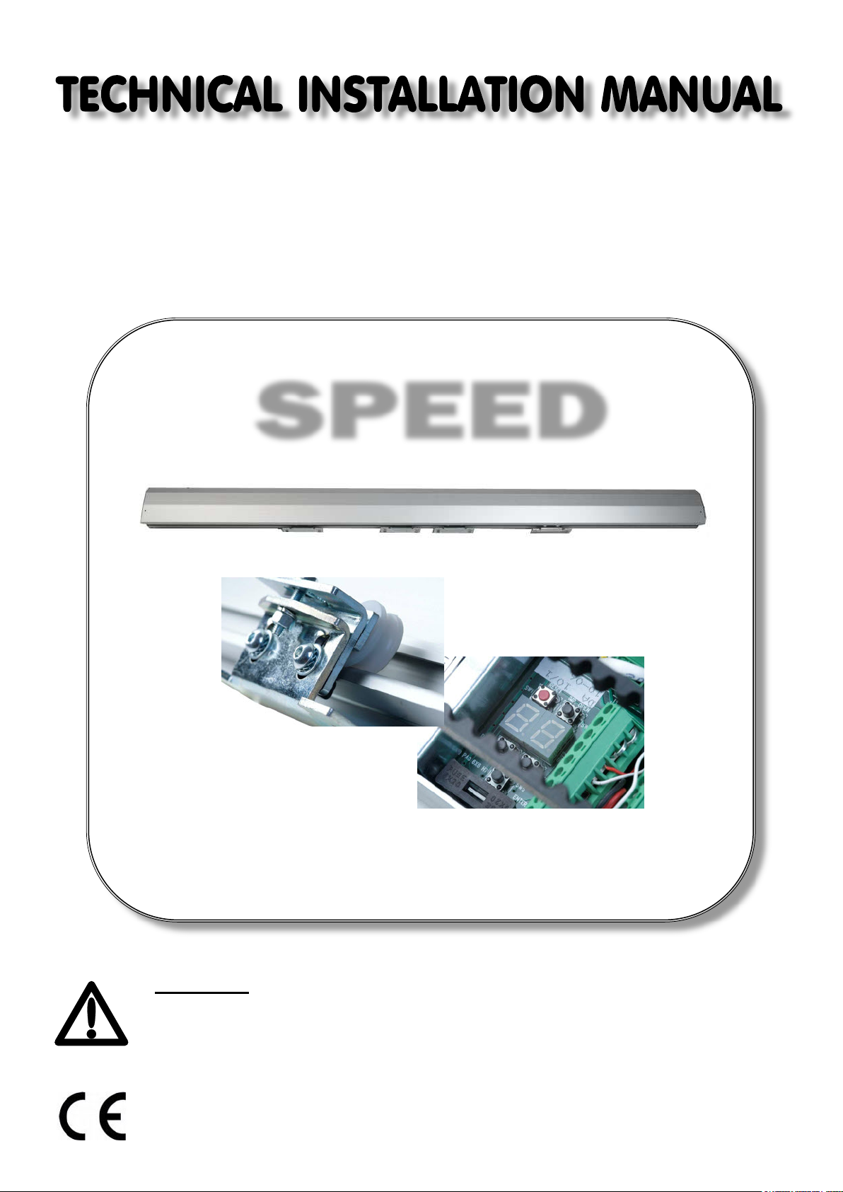
AUTOMATION
FOR SLIDING DOORS
SPEED
WARNING!! Before installing, thoroughly read this manual that is an integral
part of the pack
Our products if installed by qualified personnel capable to evaluate risks,
comply with norms UNI EN 12453, EN 12445
The CE mark conforms to European directive
EEC 89/336 + 92/31 + 93/68 D.L. 04/12/1992 N. 476.
Page 2
GENERAL PROSPECTUS......................................................................................
2
TECHNICAL DATA..................................................................................................
2
DIMENSIONS ..........................................................................................................
ACCESSORIES HOUSING......................................................................................
INSTALLATION........................................................................................................
ELECTRIC LOCK WITH MANUAL RELEASE........................................................
SUPPORT FOR GLASS WINGS.............................................................................
CONTROLL UNIT.....................................................................................................
CONTROL UNIT AND SELECTOR SCHEMES.......................................................
SAFETY PRECAUTIONS ........................................................................................
Power supply
230Vac
Max weight 2 leaves
80+80 Kg
Rated frequency
50Hz
Protection rating
IP44
Nominal power
50W
Weight
4Kg/mt
Protection fuse
2A
Backup battery (optional)
12V 1.2 Ah
External accessories power supply
24Vdc
Noise level
<30dB
Max weight single leaf:
120 Kg
Working temperature
- 20\+55°C
3
3
4>7
8
9
10>15
17
19
GENERAL PROSPECTUS
The sliding door automations allow a fluid and silent movement.
The doors will arrest to the slightest obstacle and in the event of a power outage the
door could be manual released.
AUTOMATION PROSPECTUS
Ÿ Stamped and anodized aluminum structure
Ÿ Quick access to the equipment
Ÿ Belt drive with automatic tensioning system.
Ÿ Galvanized steel trolleys with horizontal automatic adjustment, vertical manual
adjustment and nylon wheels (lubrications not required)
Ÿ Control panel supply: 24 Vac 6 A with microprocessor
Ÿ Digital programming of operating parameters with permanent memory
Ÿ Motor speed control with PWM signal.
Ÿ Optical encoder input with wiring test
Ÿ Maneuvers and alarms will be indicate in a 7 segments display and by acoustic
warning signals
Ÿ Operations counter and maintenance warning
Ÿ Emergency Automatic opening with backup battery (optional).
Ÿ Control with digital selector(optional)
TECHNICAL DATA
Page 3
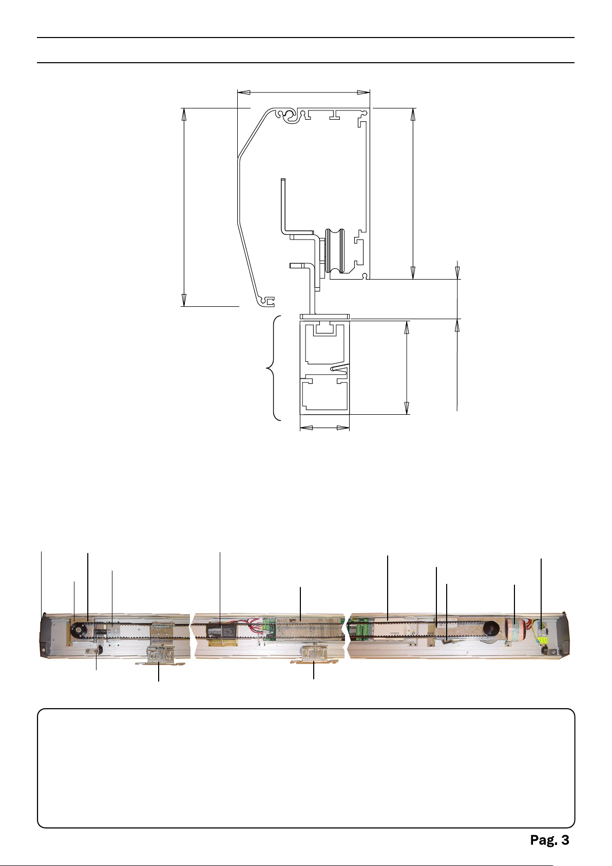
DIMENSIONS
160 mm
ANTIPANIC SYSTEM
107 mm
138 mm
COMPONENTS HOUSING
1
2
4
3
12
13
75 mm
15 - 25 mm
45 mm
5
6
14
7
8
9
11
10
1. Side caps
2. Support driven pulley
3. Electric lock with manual release
4. Belt Tensioner
5. Back-up battery
6. Control unit
7. Photocells amplifier
8. Motor support with pinion
9. Motor optical encoder
10. Transformer
11.
Input Power supply terminal
12. Mechanical limit switch
13. Pulling cart
14. Free cart
Page 4
CONSIDERATIONS FOR INSTALLATION
Ÿ
The installation and testing operations must be performed solely by qualified
personnel in order to guarantee the proper and safe operation of the sliding door.
Ÿ
The company declines any responsibility for damage caused by incorrect
installations due to incompetence and/or negligence.
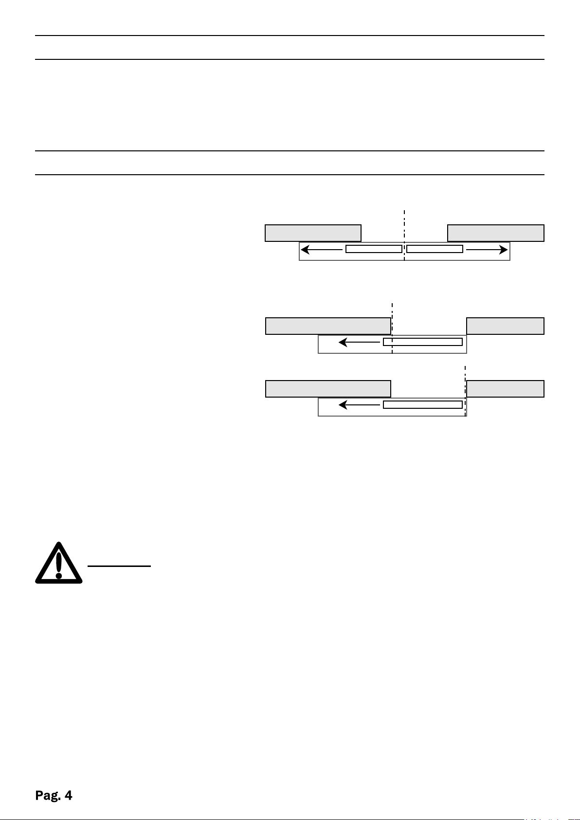
INSTALLATION
METHOD POSITIONING
2 WINGS
The center of the profile should
coincide with the center of the
opening passage.
1 WING
The center of the profile should
coincide with the end of the
opening passage or the end of
the profile should coincide wit the
end of the opening passage.
COVERALL FASTENING
Remove the cover. Drill holes on the front side of the coverall. it is recommended
not to exceed a distance of 600 mm between the holes.
WARNING
then wipe away any aluminum residues from the belt and the guide.
Calculate the measurements for the vertical dimension given by the height of the doors,
considering the vertical distance of the carriages. ( see coveralls dimensions )
Place the coverall parallel to the floor surface and mark the holes.
Provide holes for cable entry or open those pre-cutted. Fast the coverall to the wall
using screws (minimum diameter of 5.)
Protect the electronic equipment before you drill the holes, and
Page 5
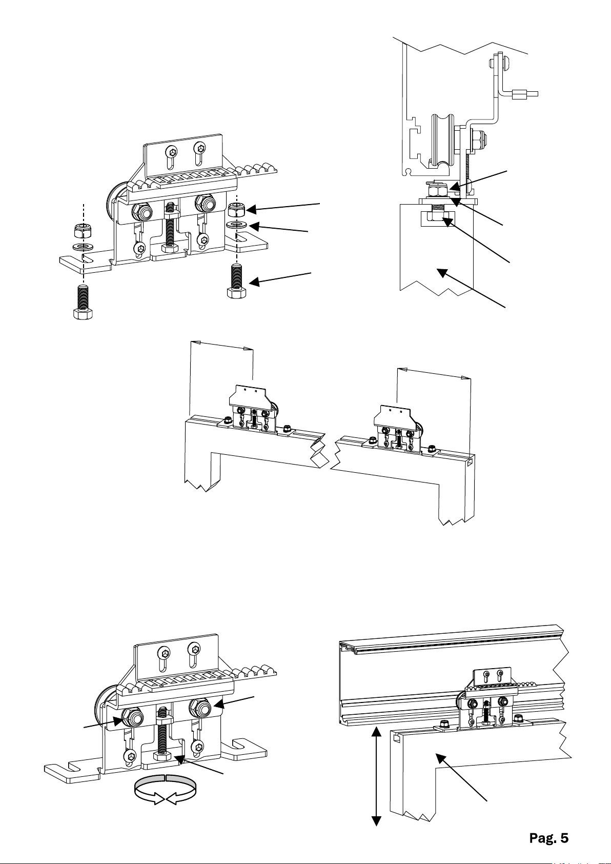
LEAVES HOOKING
Place the leaf under the carriages of the coverall and
fast with 8/10 mm screws( not supplied), to a distance
from the ends of the leaf of 100/150 mm.
Nut
Nut
100/150mm
Washer
Screw
Washer
Screw
Door
100/150mm
LEAVES HEIGHT ADJUSTMENT
To adjust the height of the leaves loosen the two nuts A and through the screw B
make the adjustments : screwing the leaf goes up, unscrewing the leaf goes down.
At the end of the operation block the nuts A.
Nut A
Nut
Screw B
Leaf
Page 6
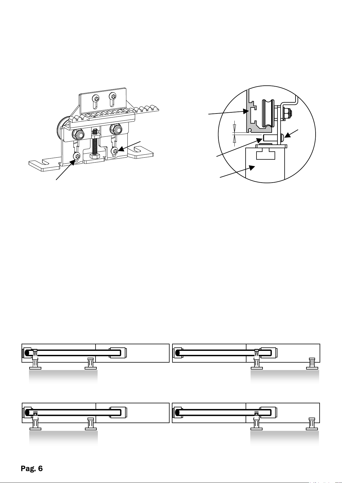
ANTI-DERAILMENT SETTINGS
Adjust the pins C to avoid the derailment of the trolleys.
Loosen the screw D and adjust the pins at a distance of about 1mm from the bottom
of the profile of the coverall.
Coverall
profile
Screw D
Screw D
Pin C
Leaf
Screw D
CONFIGURATION RIGHT - LEFT
All our coveralls are assembled in such a way that the procedures for inversion are
minimum, without changes of space between components or belt length.
2 LEAVES : the pulling trolleys will not have obstacles in the stroke, they will run
under the equipment using the full length of the coverall.
1 LEAF : to switch from the left to the right you just need to reverse the belt
hook.
1mm
Closing
Opening
LEFT
Opening
RIGHT
Closing
Page 7
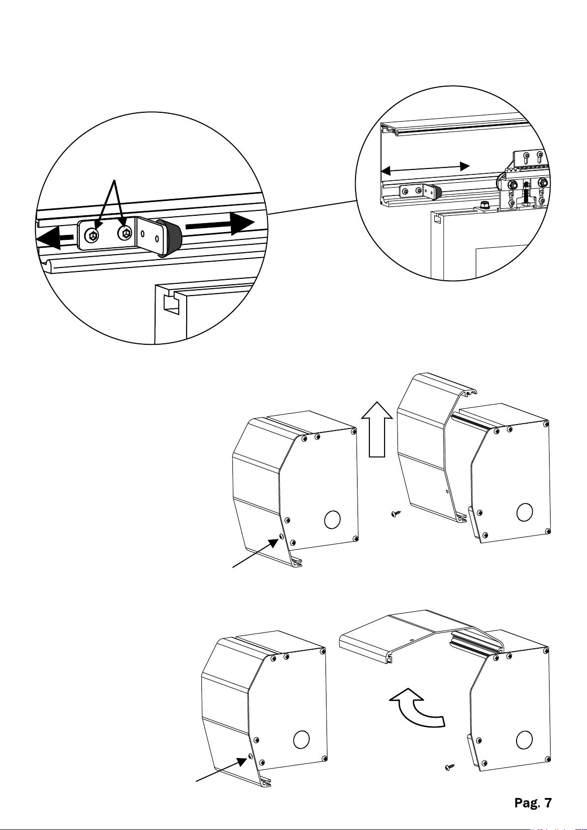
LIMIT SWITCH ADJUSTMENT
Adjust the limit switches to determine the stroke of the door.
Ÿ Loosen the screws A and adjust to the desired stroke.
Ÿ Tighten the two screws
Screws A
COVER REMOVAL
To remove the front
cover, unscrew the two
screws B at the ends of
the box and lift
To lift the front cover,
unscrew the two screws
B at the ends of the box
and rotate
Screw
Screw B
Page 8
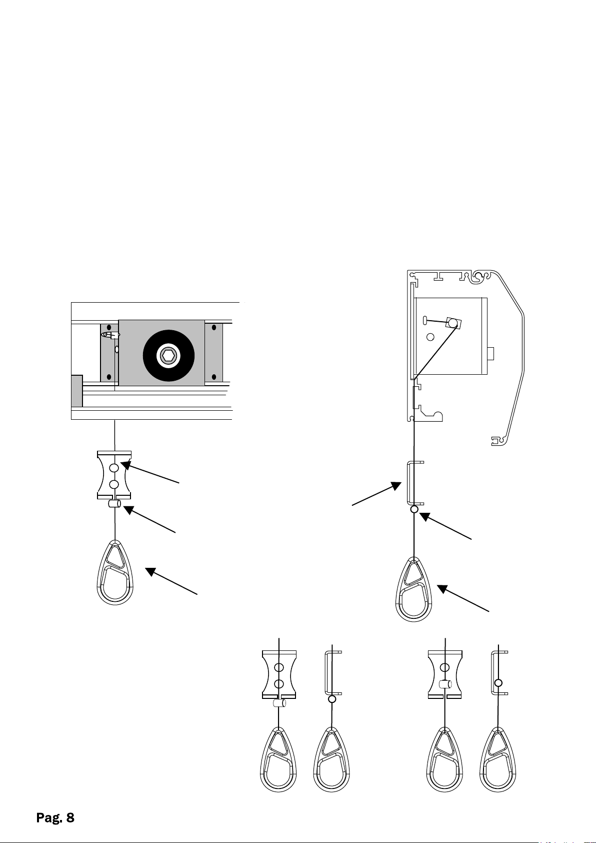
ELECTRO LOCK WITH MANUAL SYSTEM (optional)
The electric lock is the safest way to lock the door. In case the backup battery is not
present or in the event of failure of the latter, the system is equipped with external
manual release.
The working principle is based on the voltage given to the steel cable that came with
their anchoring systems.
WARNING! Adjust the force according to the diameter of the cable.
With the box open you will notice the steel cable that comes out on the on the left
side of the pulling pulley. Drill a hole of 2.5mm perpendicular to the cable.
Fix the bracket onto the wall to keep the electro lock pulled permanently
Bracket
Clamp
To unlock manually pull the
plat and hook the clamp under the bracket.
To lock put the clamp inside
the bracket
Bracket
Clamp
Plate
Plate
UNLOCKED
LOCKED
Page 9
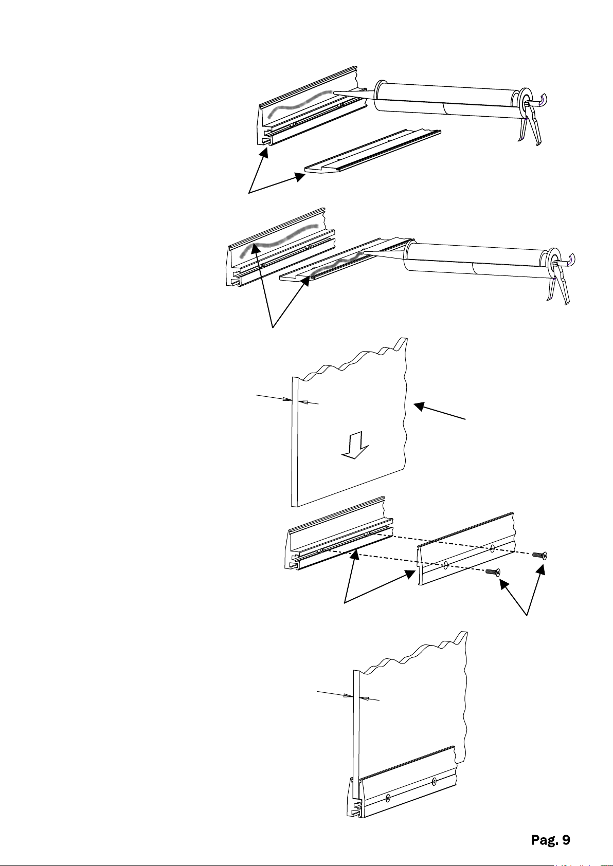
SUPPORT FOR 10mm thick GLASS WINGS (Optional)
Apply silicone on the
aluminum support.
Support
Silicone
Insert the glass wing
(thickness 10mm)
Block the support with the screws
and wait at least 48 hours for
drying
10mm
Glass wing
Support
Screws
10mm
Page 10

MANUAL FOR SLIDING DOOR CONTROL UNIT
General description:
Ÿ Power supply: 24 VAC - 6A
Ÿ Back-up battery: 12V 2A Pb with integrated charger and functional test every 12 hours
Ÿ Output: 28 VDC +/- 15% with 500 mA fuse
Ÿ Encoder input (direction and pulse) with cable test
Ÿ Motor speed control with PWM signal
Ÿ Output for electromagnetic door lock with PWM signal
Ÿ User-programmable operating parameters
Ÿ Non-volatile (flash) data storage that does not require back-up power
Ÿ Open/close cycle meter with 2 selectable maintenance alarm settings
Ÿ Audible alarms for alerts
Ÿ Seven-section digit for operation messages
Ÿ Normally open auxiliary contact for doors in motion (optional)
Parameter Programming
Entering User-programmable parameters
If the PIN code has been entered correctly, the display will read ‘1’ to indicate the first
user-adjustable setting.
To change the value of the setting, select the desired parameter by pressing ‘INVIO’. The
parameter number will increase by 1 each time the key is pressed, and when the desired
parameter is reached use the UP and DOWN keys to change its setting.The display will flash
when the setting can be changed.
To move to another parameter, press INVIO until the desired parameter is reached and use the
UP and DOWN keys to set the desired value.
The settings will be saved automatically a few seconds after no further keys are pressed, or can
be saved immediately by pressing the INVIO button until the last parameter is reached and then
one further time to confirm the values.
The new settings are confirmed with the message ‘rd’ on the display and a 1 second tone.
Figure 1 contains a list of all user-programmable parameters.
Unit setup
After installation, the control unit will automatically measure the size of the door system; if the
system is connected correctly, a few seconds after providing power the setup program will start.
The door will slide slowly to position itself first at the mechanical stop for the open position and
then at the mechanical stop for the closed position.
If the entire procedure is completed successfully the line on the screen will flash, while if errors
were encountered the screen will display the error message . (List of messages viewable on the
screen)
The setup program can be activated at any time using the ‘RESET’ feature (see input selector).
Caution without power supply, also with battery inserted, the control board do not enter in setup
mode.
Note: during the setup program the radar proximity sensors are disabled, so to prevent
injury please ensure that no people or animals approach the doors during this process.
The botton test it is able to do the test directly on the control board.
Page 11
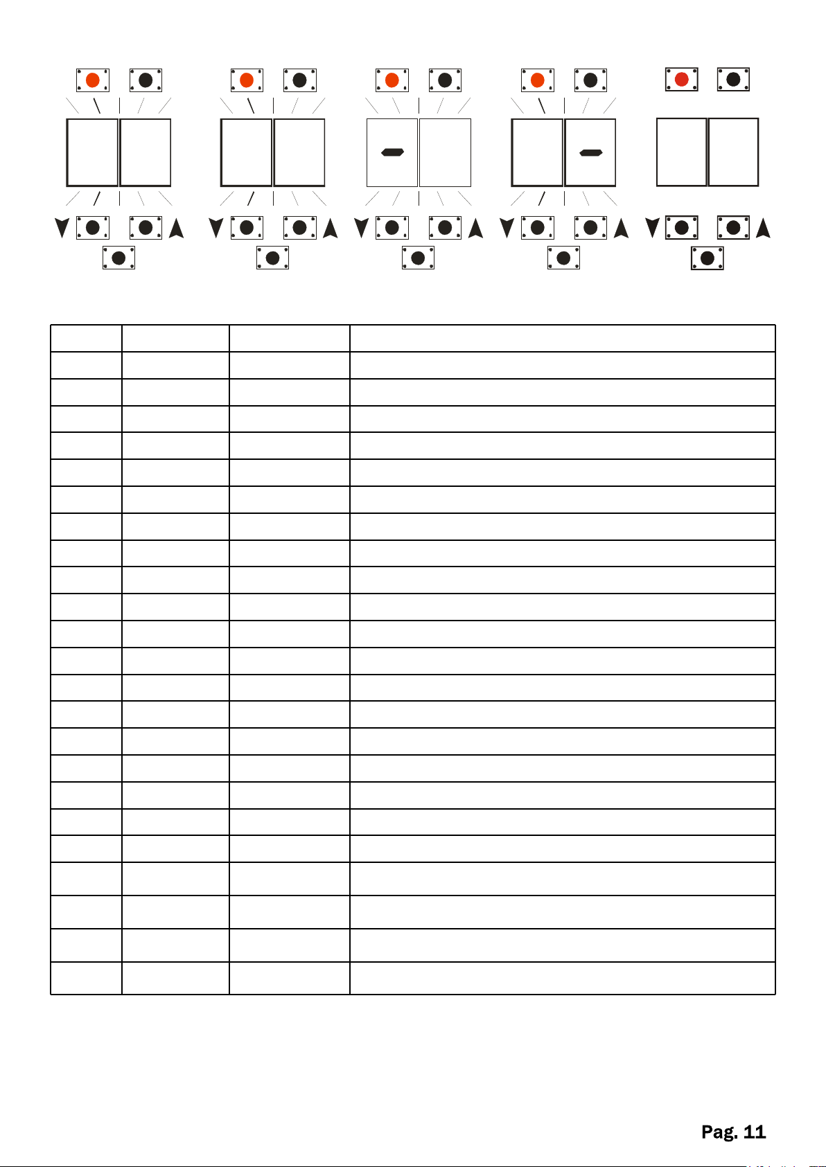
TESTRESE T
N Pr.
RANGE
UNITS
DESCRIPTION
1
2 – 18
Amp.
Motor power consumption on opening
2
2 – 18
Amp.
Motor power consumption on closing
3
1 – 5
cm/sec2
Acceleration when opening
4
1 – 5
cm/sec2
5
10 – 60
cm/sec
6
10 – 60
cm/sec
Speed when closing
7
3 – 15
cm/sec
Approach speed when opening
8
3 – 15
cm/sec
Approach speed when closing
9
3 – 35
cm
pproach distance when opening
10
3 – 25
cm
Approach distance when closing
11
5 – 90%Partial opening percentage
12
0 – 5
cm
Manual travel
13
0 – 30
sec.
Delay for automatic closing
14
0 – 30
sec.
Delay for auxiliary closing
15
0 – 30
sec.
Delay for partial closing
16
1 – 10
decimi/sec
Time for electric lock
17
0 – 15
number
System configuration menu 1
18
0 – 15
number
System configuration menu 2
19
0 – 1
number
System configuration menu 3
number
1st digit PIN code (A)
2nd digit PIN code (B)
3rd digit PIN code (C)
4th digit PIN code (D)
TESTRESE T
TESTRESE T
TESTRESE T
TESTRESET
3
Figure 1. List of programming parameters
5
INVIO
I
P
INVIO
L
INVIO
P
EE
INVIO
Acceleration when closing
Speed when opening
INVIO
20 0 – 9
21 0 – 9 number
22 0 – 9 number
23 0 – 9 number
NOTE: during the programation remember that the speed and weight of the
leaves are proportional to the current drawn by the motor, then in case of
changes in the speed you need to adjust current supply (range 1-2)
Otherwise you the control panel will report an obstacle error due to the over
absorption for the output current
Page 12
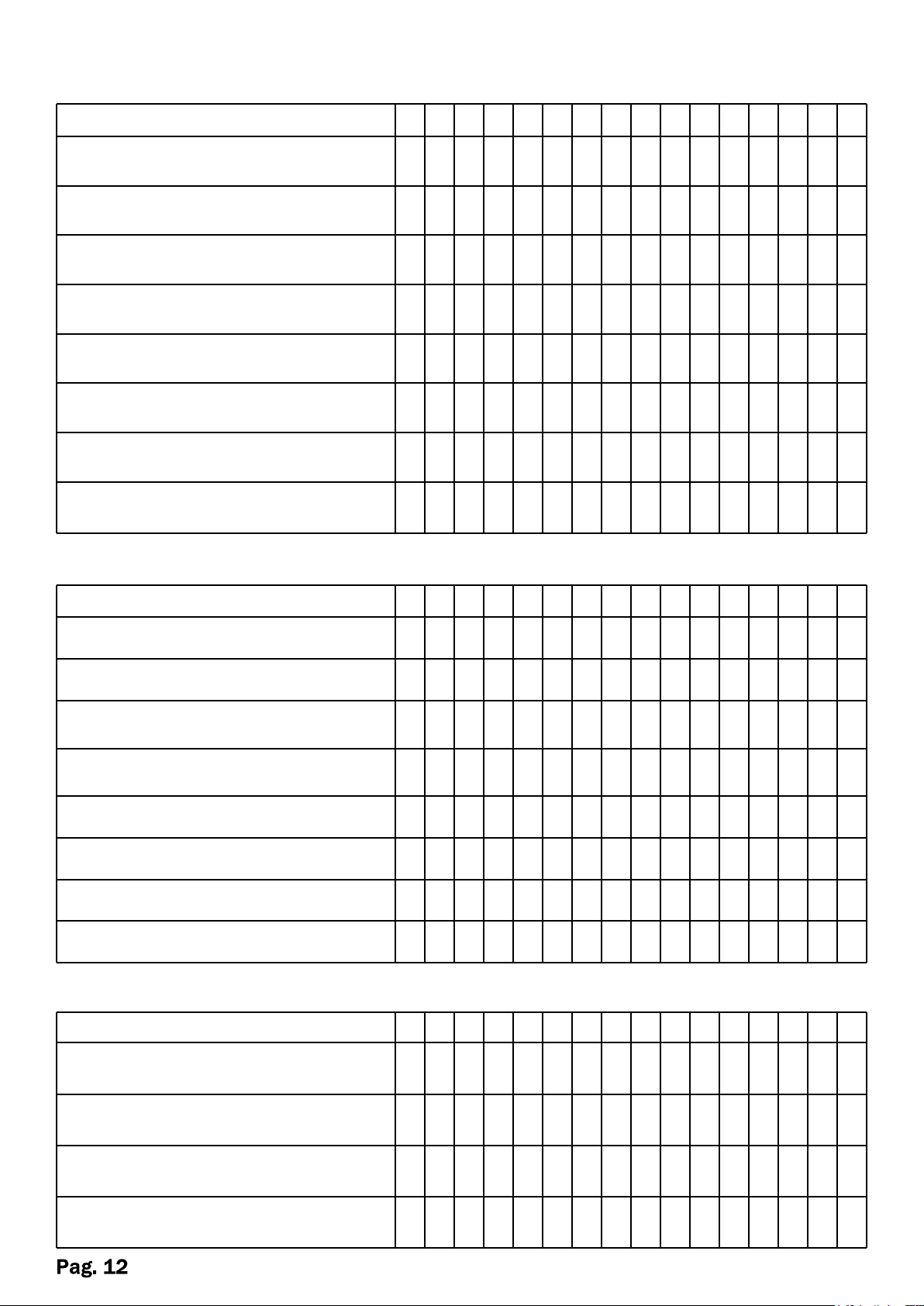
(Index no. 17) - 1stMENU - configuration
1011121314
15
close using battery power in case of
power failure
xxxxxxx
x
open using battery power in case of
power failure
xxxxxxx
x
when closed/switched off, open in
case of power failure
xxxxxxx
x
when closed/switched off, close in
case of power failure
xxxxxxx
x
Electromagnetic lock closed without
power
xxxxxxx
x
Electromagnetic lock closed with
power
xxxxxxx
x
security inputs into logic normally
closed
xxxxxxx
x
security inputs into logic normally
open
xxxxxxx
x
1011121314
15
xxxxxxx
x
xxxxxxx
x
set alert for 1,500,000 mechanical
cycles
xxxxxxx
x
set alert for 300,000 mechanical
cycles
xxxxxxx
x
xxxxxxx
x
xxxxxxx
x
xxxxxxxxxxxxxxx
x
FUNCTION
1011121314
15
battery management
(battery installed)
xxxxxxx
x
battery management
(battery not installed)
xxxxxxx
x
Auxiliary output for door in motion
relay enabled(optional)
xxxxxxx
x
Auxiliary output for door in motion
relay disabled (see above)
xxxxxxx
x
FUNCTION
0 1 2 3 4 5 6 7 8 9
(Index no. 18) - 2st MENU - configuration
FUNCTION
audible alarm enabled
audible alarm disabled
mechanical cycles meter enabled
mechanical cycles meter disabled
reset mechanical cycles meter
0 1 2 3 4 5 6 7 8 9
(Index no. 19) - 3st MENU - configuration
0 1 2 3 4 5 6 7 8 9
Page 13
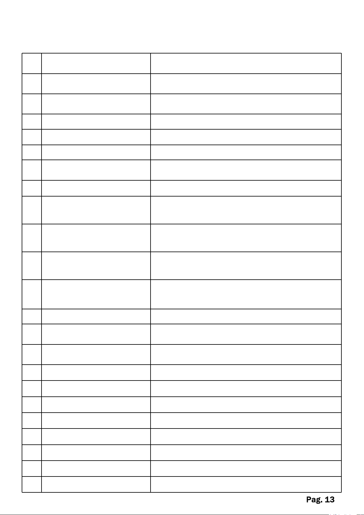
Motor power consumption on
opening
signal strength above which the control unit registers
blockage when opening
Motor power consumption on
closing
signal strength above which the control unit registers
blockage when closing
system initial response time when opening,
1 = minimum, 5 = maximum
Approach speed when
opening
Approach speed when closing
percentage in reference to closed door, used to open
door when partial opening is selected
0 = door is actively held shut; 1 = door opens freely;
>2 = automatic opening when door is manually
pulled from closed position
Pause in open position before closing in response to
auxiliary command
Pause in partial open position before closing from
partial opening
Description of user-programmable parameters
Index
1
2
3
Acceleration when opening
4
Acceleration when closing system initial response time when closing
5
Speed when opening speed when opening until end of acceleration ramp
6
Speed when closing speed when closing until end of acceleration ramp
7
8
Approach distance when
9
opening
Approach distance when
10
closing
11
Partial opening
12
Manual travel
13
Delay for automatic closing Pause in open position before closing automatically
14
Delay for auxiliary closing
speed of the approaching phase when opening
speed of the approaching phase when closing
distance from open door stop when the door is
slowed to reach the programmed approach speed
distance from closed door stop when the door is
slowed to reach the programmed approach speed
15
Delay for partial closing
16
Time for electromagnetic lock delay before electromagnetic lock is activated
17
Menu 1 programming menu no. 1
18
Menu 2 programming menu no. 2
19
Menu 3 programming menu no. 3
20
1st digit of PIN code **
21
2nd digit of PIN code **
22
23
rd
3
digit of PIN code
4th digit of PIN code
**
**
Page 14
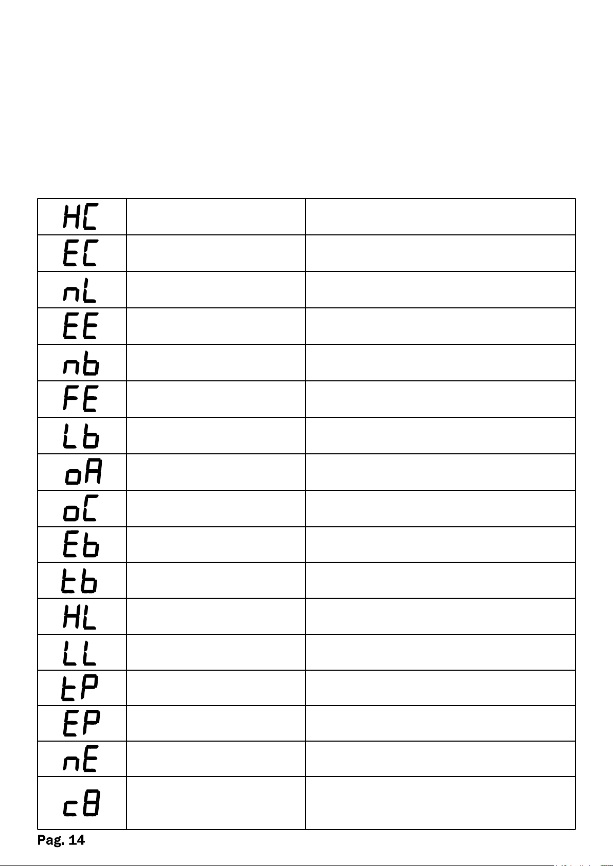
Short circuit in motor and/or
malfunctioning power supply electronics
POWER CONSUMPTION
ERROR
Over-consumption of power while
operating.
No power available and/or power supply
fuse interruption.
No encoder signal. Wire broken and/or
encoder malfunction.
No battery installed. Wire broken and/or
battery fuse interruption
Memory problem. Processor malfunction,
must be replaced.
Insufficient battery voltage, battery dead.
BLOCKAGE ON
OPENING
BLOCKAGE ON
CLOSING
Indicates when the battery test is being
carried out.
Voltage of AC power supply 230 V too
high.
Voltage of AC power supply 230V too low.
Mechanical impediment to the start of
the reset phase. The c8 will be repeated
continuously
Display functions on the unit:
Ÿ With the door closed at rest position, the screen on the right shows a flashing
horizontal line
Ÿ When door is moving the screen shows the power distributed by the control unit
Ÿ In case of alerts or anomalous functioning the screen will display a message from
the following table
Ÿ View user-programmable parameters
Ÿ View number of cycles
List of messages viewable on the screen
HIGH CURRENT
NO LINE
ENCODER ERROR
NO BATTERY
FLASH ERROR
LOW BATTERY
Blockage encountered during opening.
Blockage encountered during closing.
BATTERY ERROR Battery failure, must be replaced.
BATTERY TEST
HIGH LINE
LOW LINE
TEST PINCODE PIN code being checked
PINCODE ERROR Incorrect PIN code entered
SAFETY ERROR Safety nc open or not installed correctly
ENGINE X ERROR
IMPEDIMENT
Page 15
Security code (PIN)
Press the INVIO button once and the message 'IP’ (Insert Pin) will appear on the
screen, and after a moment the letter ‘A'-- the first digit of the 4-digit code--will
appear, and a moment later a flashing number '0' will be displayed.
At this point, use the 'UP' and 'DOWN' keys to enter the first digit of the PIN code.
Press INVIO to move on to the second digit (letter ‘B'), wait until the a flashing
number '0' appears on the screen, and as before use the 'UP' and 'DOWN' keys to
enter the second digit of your PIN.
Press INVIO to confirm and enter the remaining digits using the same process
described above.
When the last digit has been confirmed, the screen will display 'tP' to indicate that
the PIN code is being checked; if the code is correct the attention tone will sound
two short tones and the screen will show the first user-programmable parameter.
If the PIN code was entered incorrectly, the message 'EP' will be displayed and a
tone will sound for approximately 1 second, then the control unit will automatically
return to standby mode showing the flashing line, and will not allow the
user-programmable parameters to be modified.
The control unit has a timer function so that if no keys are pressed for 10 seconds
while in programming mode, the information entered up to that point will be saved
and the unit will exit the programming mode.
Setting all 4 digits of the PIN to 0 turns off the security code.
The control unit comes with the 4 digit PIN code set to 0; please set a personal
security code to protect the user-programmable settings.
If the PIN code is not required (0000), press INVIO to go directly to the first
user-programmable parameter (Index 1).
Unlocking password PIN-CODE procedure
When you turn on the card, close to ground at the same time the interior and the
exterior radar ;
The display will show the message: "Rd" (read) followed by a beep that signals the
PIN CODE restore factory default.
Page 16
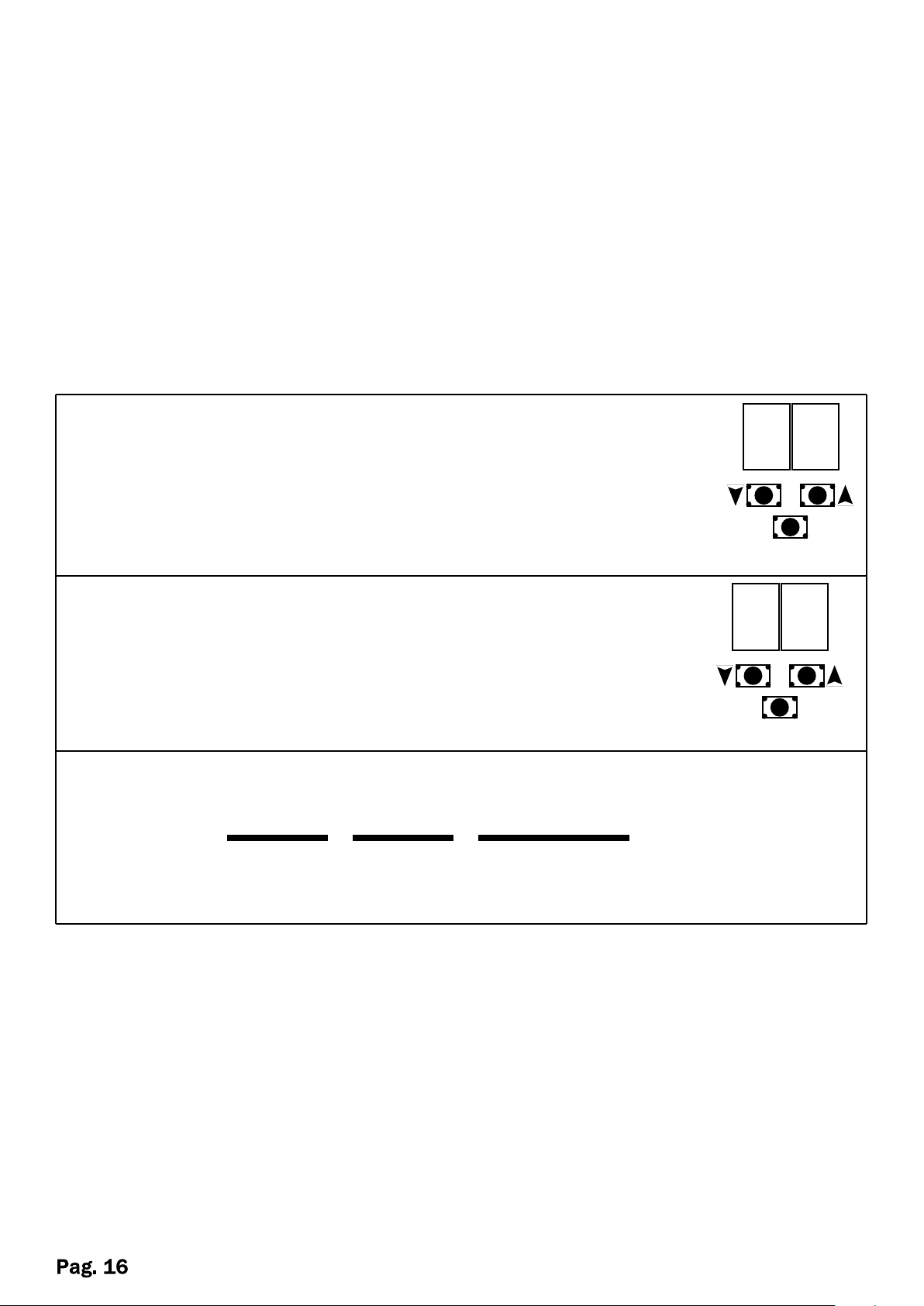
View number of cycles carried out
Press the UP key and for a few seconds the number that
corresponds to the ‘low’ part of the figure is displayed.
After a few seconds the screen returns to displaying the flashing line.
The two numbers are combined as in the following illustration
Introduction.
The meter presents the number of cycles in multiples of 1000, so the number
displayed must be multiplied by this factor.
This data is recorded in permanent memory, but always in multiples of 1000 cycles.
The number of cycles can only be read when the system is in stand-by, that is, when
the screen displays a flashing horizontal line.
In addition, the mechanical cycles meter must be enabled in Menu 2 (index 18).
The following is an example.
Press the DOWN key and for a few seconds the number that
corresponds to the ‘high’ part of the figure is displayed.
After a few seconds the screen returns to displaying the flashing
line.
04
INVIO
C
37
INVIO
04 37 000
HIGH
PART
Therefore, this unit has completed 437,000 cycles
If the buzzer option is enabled, upon reaching the maximum number of cycles the
system will indicate the ‘unit maintenance' status by sounding a 1 second audible
alarm at 1 hour intervals when the door is open.
LOW
PART
MULTIPLY
X 1000
C
LATEST NOTIONS
The contacts -0V are in series between them, it is recommended the distribution of
equipments for all the available inputs.
When the contact 9-10 is closed the door will make a partial opening even if the
selector is in close position.
Is very useful to allow opening from the outside even with the automation blocked.
The safety contacts 22,20,19 if not used close to ground through a bridge.
Page 17
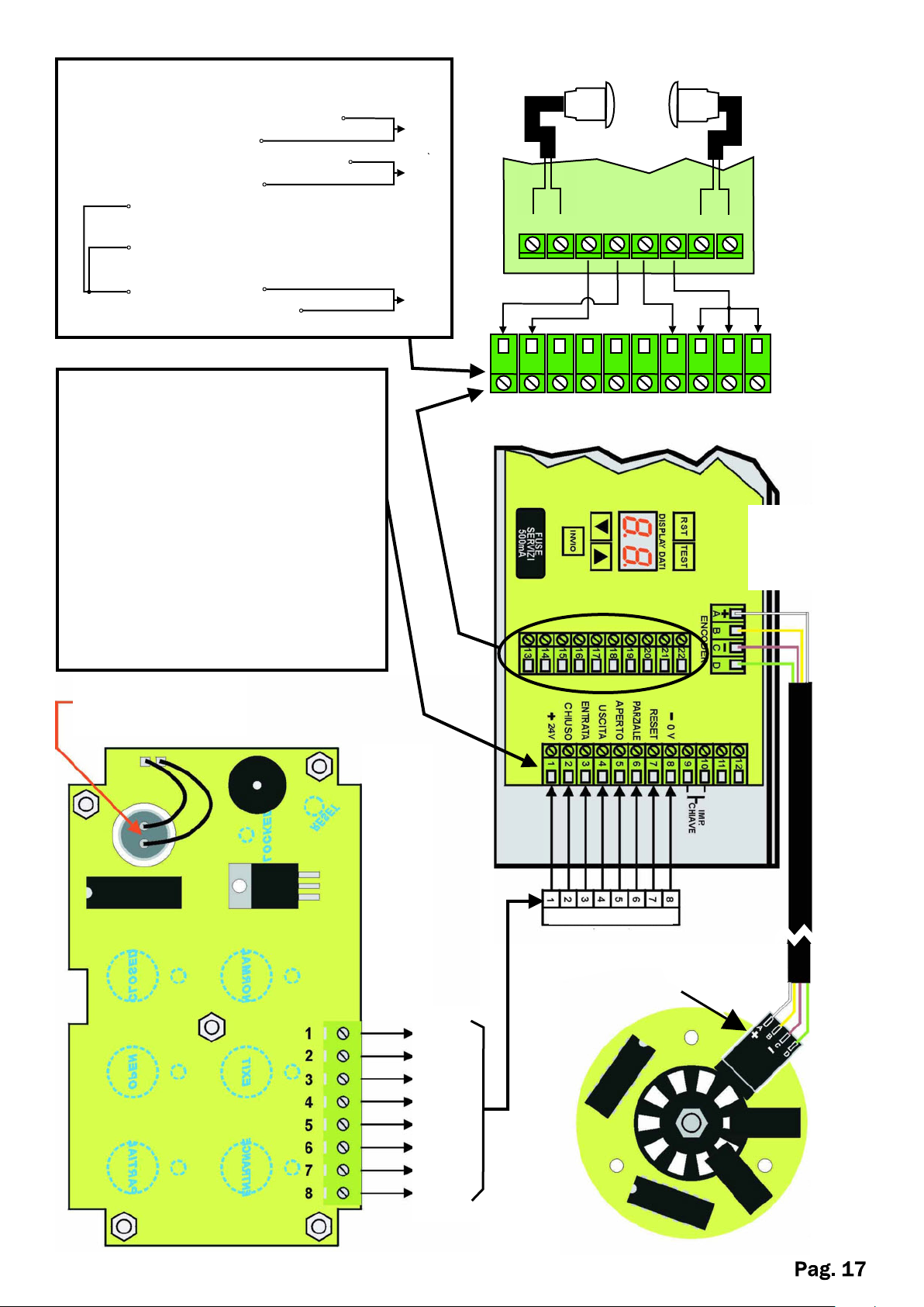
13. + 24V
14. - 0V
15. INTERNAL RADAR
16. COMMON
17. EXTERNAL RADAR
18. COMMON
19. photocell A
AMPLIFIER CONTACT
N.C
20. photocell B
N.C
AMPLIFIER CONTACT
21. COMMON
22. STOP MOTOR
1. + 24V SELECTOR
2. CLOSED
3. ENTRY
4. OUTPUT
5. APEN
6. PARTIAL
7. RESET
8. - 0V SELECTOR
9-10. CONTACT FOR PARTIAL
OPENING IN CLOSE. KEY
PULSE
11-12. AUXILIARY NOT AVAILABLE
N.O
N.O
N.C
Photocell
N.C
Tx
RED
N.C
SHIELD
N.C
Rx
SHIELD
2 3 4 5 6 7 8 9
-
+
13 14 15 16 17 18 19 20 21 22
WHITE
-
+
24V
Photocells
Amplifier
LN1011
A= BROWN
B= WHITE
C= BLUE
D= GREEN
0.22 WIRE
7Cm+NEOPRENE
NSULATION ON KEY
DIGITAL SELECTOR
INSIDE OF
+24V
CLOSED
IMPUT
OUTPUT
OPEN
PARTIAL
RESET
- 0 V
SELECTOR
4 POLE AMP
CONECTOR
ENCODER FROM
ABOVE
Page 18
NOTE
Page 19

SAFETY PRECAUTIONS
These warnings are an essential, integral part of the product and must be given to the user. They
provide important indications on the installation, use and maintenance and must be read carefully.
This form must be preserved and passed on to subsequent users of the system. The incorrect
installation or improper use of the product may be dangerous.
INSTALLATION INSTRUCTIONS
• The installation must be performed by professionally skilled personnel and in compliance with
current local, state, national and European legislation.
• Before beginning the installation, check the integrity of the product.
• The laying of cables, electrical connections and adjustments must be workmanlike performed.
• The packing materials (cardboard, plastic, polystyrene, etc.) are a potential hazard and should
be disposed of correctly and not left within reach of children.
• Do not install the product in potentially explosive environments or environments disturbed by
electromagnetic fields. The presence of inflammable gases or fumes is a grave danger to
safety.
• Set up a safety device for overvoltage, a disconnecting and/or differential switch suitable for
the product and conforming to current standards.
• The manufacturer declines any and all responsibility for product integrity, safety and operation
in the event incompatible devices and/or components are installed.
• Solely original spare parts should be used for repairs and replacements.
• The installer must provide all the information relating to the operation, maintenance and use of
the individual parts, components and system as a whole.
WARNINGS FOR THE USER
• Read the instructions and enclosed documentation carefully.
• The product must be used for the express purpose for which it was designed. Any other use is
considered improper and therefore hazardous. In addition, the information given in this
document and in the enclosed documentation may be subject to modifications without prior
notice. It is given as an indication only for product application. The company declines any
responsibility for the above.
• Keep products, devices, documentation and anything else provided out of reach of children.
In the event of maintenance, cleaning, breakdown or faulty operation of the product, cut off the
power and do not attempt to operate on the product. Contact solely the professionally skilled
personnel responsible for these operations. Failure to adhere to the above indications may be
dangerous.
Page 20

The data and images are for guidance only
VDS reserves the right to change at any time characteristics of the products described in
its sole discretion, without notice.
Via Circolare p.i.p. N° 10
65010 Santa Teresa di Spoltore (PE) - ITALY
Tel. +39 085 4971946 - FAX +39 085 4973849
www.vdsconsorzio.it - [email protected]
Rev. 3-01/14 ING
 Loading...