

Page 1
QUICK REFERENCE GUIDE
Mains Power Supply WHP425
– Especially for WS425 Ultrasonic Wind
Sensors
– Both heating and operating power
available (36VDC 0.8A, 12VDC 0.03A)
– Universal power input 100… 230VAC
– Spare screw terminals and cable
gland for data line connections
– Fire resistant, non-metallic
enclosure (UL 94-5V)
– Ingress protection IP66/67 (NEMA 4X)
– Mounting kits available for ∅ 60 mm,
∅ 75 mm, and ∅ 100 mm masts
© Vaisala 2009. All rights reserved. Ref. M211016EN-B
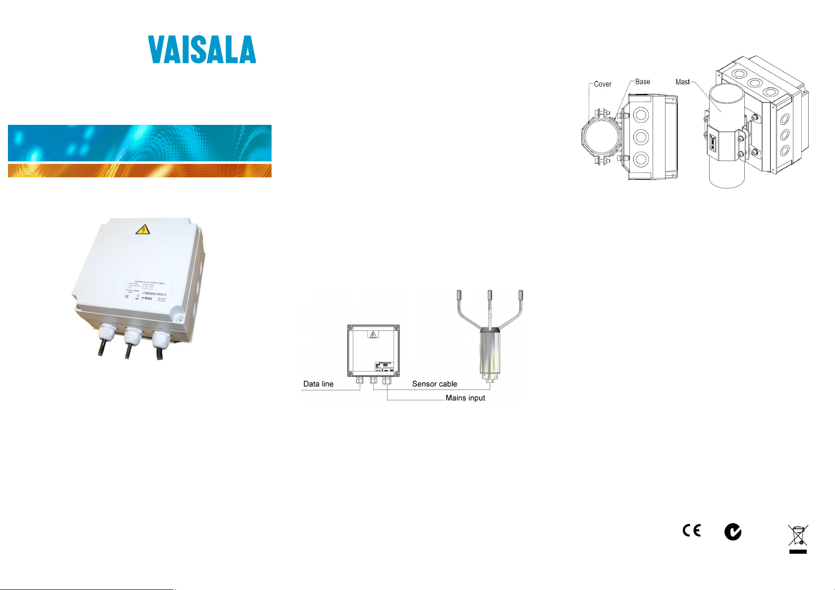
DESCRIPTION
Mains Power Supply WHP425 provides heating and operating
power for a WS425 Ultrasonic Wind Sensor or other equipment
managing with 36VDC 0.8A and 12VDC 0.03A supplies.
The WHP425 adapts automatically to all common mains power
inputs (100/115/120/230) with no need for adjustment or setting
of selector switches.
The WHP425 has a weather, water, and fire resistant housing
with ingress protection rating IP66/67 and fire resistance class
UL 94-5V. The equipment can be mounted on a wall or on a
pole mast with ∅ 60 mm, ∅ 75 mm, or ∅ 100 mm mounting kits
available. For installation to a pole mast see Figure 2.
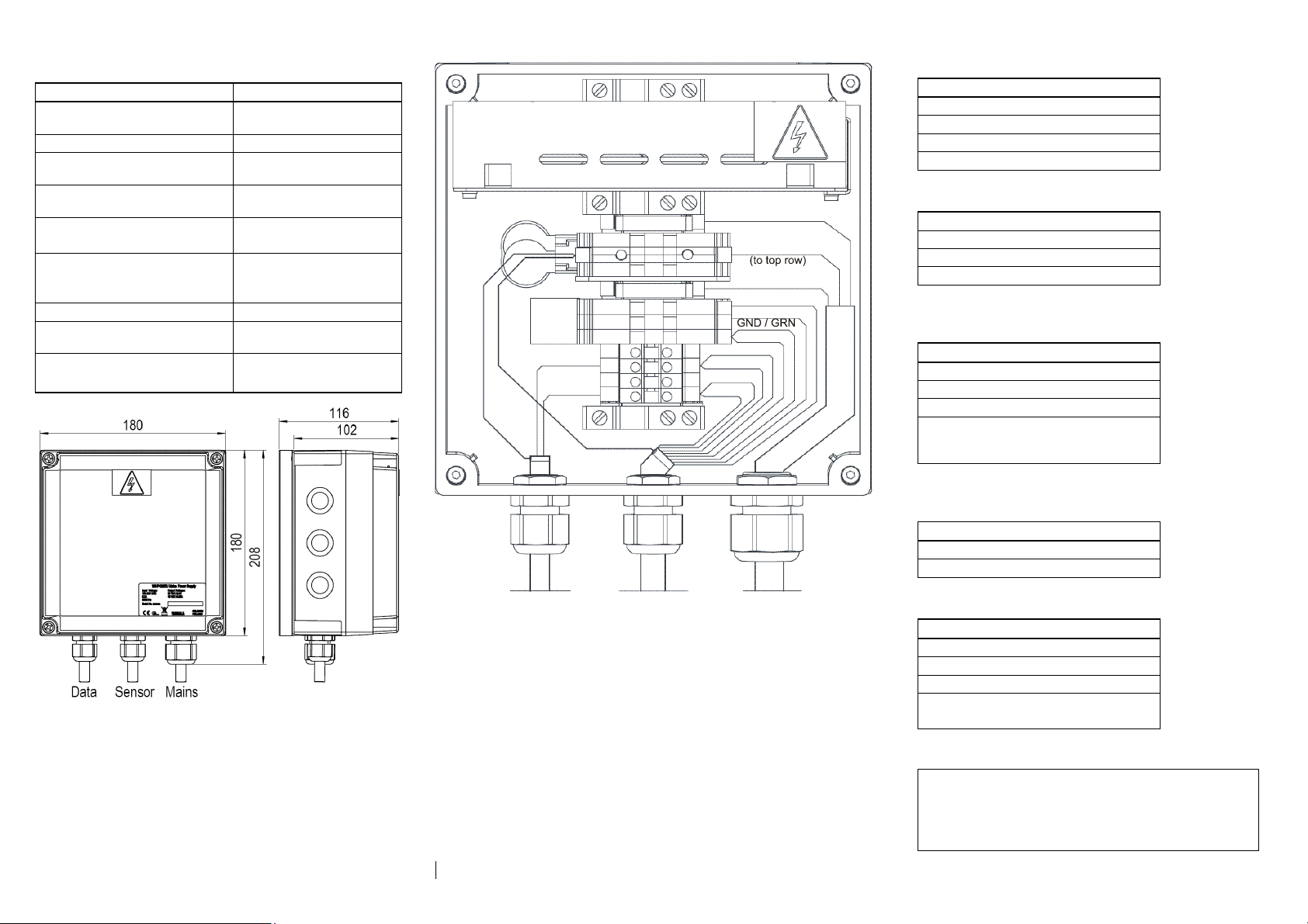
WIRING
The detailed instructions for wiring the Mains cord, WS425
sensor cable, and Data line cable are in Figure 4, on the reverse.
There are spare screw terminals inside the WHP425 enclosure
for signal wire chaining between the data line and sensor cable.
Wiring for the WS425 various data transmit modes to the spare
screw terminals (1, 2, 3, and 4) is also illustrated in Figure 4.
A simplified wiring principle is shown in Figure 1. The standard
sensor cable length is 10 meters.
Figure 1 Wiring principles
For long sensor cables, with power line total resistance > 20Ω, it
is advisable to connect a 100…220uF capacitor across +12VDC
and respective GND at the sensor end. This is to avoid power
fluctuation in the cable. An 18V transient zener diode should be
connected across the capacitor for protection.
With long sensor cables it should also be noted that part of the
heating power is stolen by the cable. For example, 20Ω line
resistance drops the sensor heating power to half of nominal.
For such cases we recommend either larger diameter wires or
multiple wires in parallel for +36VDC and respective GND.
INSTALLATION
Figure 2 Installing WHP425 to pole mast
Figure 2 illustrates mounting of the WHP425 to a pole mast with
one of the available mounting kits. Note that the equipment is
intended only for installation in a restricted access location.
Follow the procedure below:
Attach the mounting kit base part with the four screws to
1.
the metallic rear wall plate of the unit.
Place the unit to the mast at suitable height, and fasten it
2.
there by means of the mounting kit cover part attached to
the base part with the other four screws in the kit.
Switch off all live voltages! Remove the unit front cover
3.
by first removing its four plastic fastening screws.
The outlet for the mains cable shall be near the unit and
4.
easily accessible. In case the original mains cable is too
short for the application, replace it with another, carefully
observing the L/ N/ PE markings on the screw terminals
and in the diagram of Figure 4. Use the rightmost cable
gland and lastly tighten it carefully.
Enter the sensor cable through the middlemost cable gland
5.
and make the cable wiring as instructed in Figure 4.
Carefully tighten the sensor cable gland.
Enter the data line cable through the leftmost cable gland
6.
and make the cable wiring as instructed in Figure 4,
depending on the data transmit mode of the WS425.
Carefully tighten the data line cable gland.
Carefully reattach the enclosure cover with the four plastic
7.
screws.
N17728
Page 2
TECHNICAL DATA
(
)
Property Description / Value
Input power 100-230VAC max. 0.7A,
Output power 36VDC 0.8A, 12VDC 0.03A
Installation & service work
temperature
Operating and storage
temperature
Environmental protection classes IP66/67 (NEMA 4X)
Dimensions (w×h×d)
With cable glands & rear
mounting plate
Weight 1.6 kg
Housing materials Polycarbonate, stainless
Cable dimensions
Wire dimensions
50/60Hz
-40…+55
-52…+55
°C (-40…+131°F)
°C (-60…+131°F)
UL 94-5V
180 × 180 × 102 mm
180 × 208 × 116 mm
steel
∅ 5 - 10 mm, ∅ 7 - 13 mm
0.2 - 4 mm
2
RS-422 (Cable 010411):
# Sensor cable Data line
T+ / WHT T+
1
2 R+ / PNK R+
3 T- / RED T4 R- / BLU R-
RS-232 (Cable ZZ45203):
LIVE / BRN
FUSE 3.15A
S
FUSE 3.15A
12
T+ / R+
SHIELD (to top row)
SHIELD (to top row)
T- / R-
3
4
SHIELD
L1
N
T+ / WHT
1
R+ / PNK
2
T- / RED
3
R- / BLU
4
PE
12 36
G
EARTH / YELGRN
NEUTRAL / BLK
+36V / GRYPNK
+12V / BRN
GND / BLK
# Sensor cable Data line
2 SGND / YEL SGND
3 TxD / RED => TxD
4 RxD / BLU <= RxD
SDI-12 (Cable WS425CABSDI)
with power feed from Data line:
# Sensor cable Data line
2 Data / YEL Data
3 GND / BLK GND
4 +12V / BRN +12V
WARNING: In this case do NOT wire
GND/BLK and +12V/BRN to screw
terminals G and 12.
SDI-12 (Cable WS425CABSDI)
with power feed from WHP425:
# Sensor cable Data line
2 Data / YEL Data
3 Jumper to terminal G GND
Figure 3 Dimensions
SPARE PARTS and ACCESSORIES
• Switching Power Supply assembly 224500SP
• Mast mounting kit, ∅ 60 mm APPK-SET60
• Mast mounting kit, ∅ 75 mm APPK-SET75
• Mast mounting kit, ∅ 100 mm APPK-SET100
Visit our Internet pages at www.vaisala.com
DATA LINE
SENSOR CABLE
cable #010411
Figure 4 Wiring diagram with RS-485 cable
MAINS CORD
Analog (Cable ZZ45204):
# Sensor cable Data line
1 WD Ref / WHT WD Ref
Wiring for other WS425 data transmit modes is defined in the
tables on the right. Operating power is taken from terminals 12
and G in all cases other than SDI-12 with power feed from Data
line. Heating power is always taken from terminals 36 and G.
2 SGND / YEL SGND
3 WD Vout / GRY WD Vout
4 WS Fout / PNK WS Fout
or WS Vout / VIO WS Vout
WARRANTY
For certain products Vaisala normally gives a limited one-year warranty.
Please observe that any such warranty may not be valid in case of
NOTE
damage due to normal wear and tear, exceptional operating conditions,
negligent handling or installation, or unauthorized modifications. Please
see the applicable supply contract or Conditions of Sale for details of the
warranty for each product.
This manual does not create any legally binding
obligations for Vaisala towards the customer or end
user. All legally binding commitments and agreements
are included exclusively in the applicable supply
contract or Conditions of Sale.
 Loading...