

Page 1
Quick Reference Guide
WAA252 Heated Anemometer
Installation and Maintenance
INSTALLATION
Initial Check
Prior to the installation check that the WAA252 is not damaged
during transportation. Check also that the shaft rotates smoothly
without any detectable noise. It is recommended to mount the
sensor body when the cup assembly is removed. Be careful not
to cause damage to the shaft of the sensor body or to the
connector pins.
Mechanical
The Heated Anemometer WAA252 is preferably installed into
the WAC151 sensor cross arm. On bottom of the WAA252 there
is a special button-shaped temperature sensor (diameter 22 mm),
elastically attached to the bottom plate. This is for sensing the
ambient temperature and should therefore be set in good thermal
contact with the mounting support.
NOTE The three mounting screws properly tightened will
force the temperature sensor button firmly enough
against the support.
Mount the anemometer to the flange by twisting, and
3.
tighten the screws.
Finally, mount the cup assembly. Align the planes in the
4.
shaft and inside the hub. The bottom edges of the hub and
the shoulder should reach approximately the same level
(see Figure 1). Tighten the set screw.
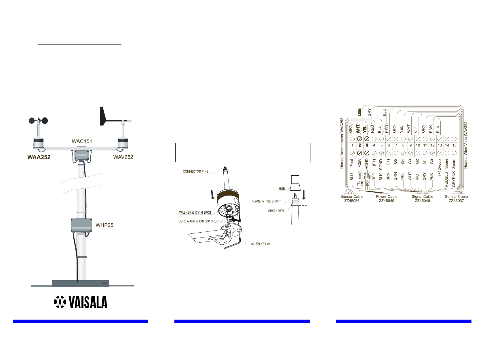
WAC151 Wiring
The wiring diagram for the WA252 system to the WAC151
Sensor Crossarm is presented in the Figure 2. The power input
wire connections are highlighted, since they differ from those for
regular wind sensors.
www.vaisala.com
0002-023
0002-024
Figure 1. Mounting of the Wind Sensor and the Hub
When installed to the WAC151 cross arm, the WAA252 is
mounted at the southern end, the northern end is reserved for the
WAV252 Heated Wind Vane.
First pre-assemble the three mounting screws, with plastic
1.
washers, to the anemometer's mounting legs.
Fit the 6-pin cable plug through the mounting flange and
2.
connect it to the sensor.
0002-025
Figure 2. WAC151 Standard Wiring for WAA252 and WAV252
When using standard power and signal cables ZZ45049 and
ZZ45048 the connections are following:
For power supply, connect the YEL,GRN, and PNK
1.
colored wires to the screw terminal #2 and the WHT,
BRN, and GRY colored wires to the terminal #3.
For signal output and grounding, connect BLU to the
2.
terminal #1 and BLK to the terminal #5.
For the optional transducer power input connect RED to
3.
the terminal #4.
For the optional power output for external transmitter
4.
move the REDBLU spare wire to the terminal #13.
As a power source use the Vaisala WHP25 Mains Power Supply,
which has a mast mountable, all-weather enclosure. For a typical
installation see the figure on the front page.
Page 2
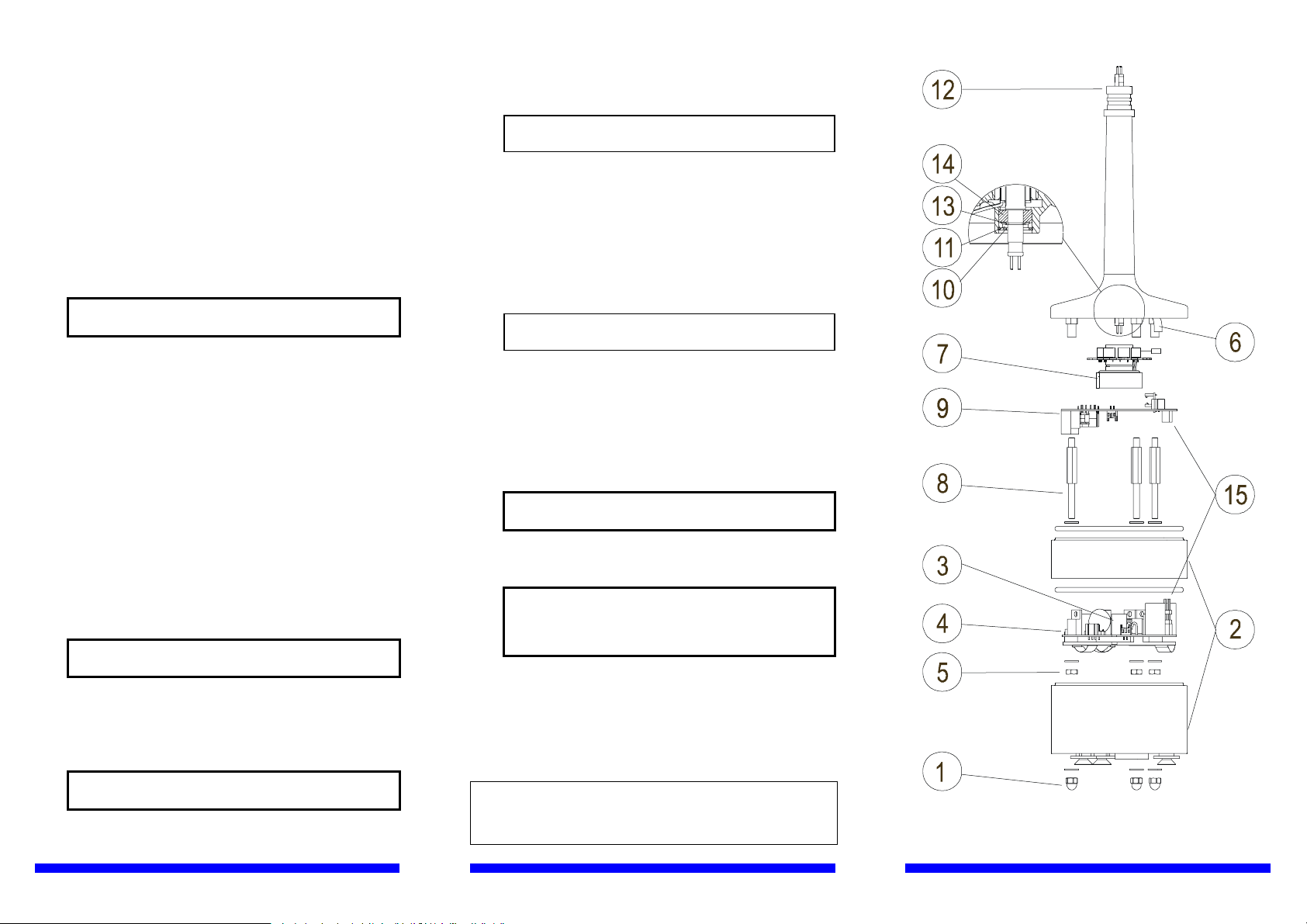
MAINTENANCE AND REPAIR
Ball bearings must be checked once a year visually and by
rotating the sensor shaft. To do this, remove first the cup
assembly as instructed below (A1.). The shaft should spin
smoothly and should not create any detectable noise.
Replacement of the bearings should be done only by a trained
technician. Steps A1 to A15 are for disassembling and steps B1
to B10 are for reassembling. The numbers in parenthesis refer to
Figure 3.
Loosen the set screw (use allen key) and carefully remove
A1.
the cup assembly.
CAUTION Be careful with the connector pins, do
not bend them.
Loosen the hex nut of the green MIL-connector at the
A2.
bottom of the sensor body (use 22 mm tool).
Loosen the three capnuts (1) at the bottom of the sensor
A3.
body (use 7 mm tool).
Remove the body cover and the O-rings (2).
A4.
Release the connector (3) of two white wires from the
A5.
power supply board (4).
Loosen the three nuts (5) at the bottom of the power
A6.
supply board (4) and remove it (use 7 mm tool).
Loosen the shaft heating foil (6) (use pliers).
A7.
Loosen the set screw of the rotating transformer assembly
A8.
(7) (use allen key).
Loosen the spacer screws (8) (use 6 mm tool).
A9.
Remove the sensor board (9) together with the rotating
A10.
transformer assembly (7).
CAUTION Handle the rotating transformer
carefully, do not drop or hit.
Remove the retaining ring (10) (use narrow-pointed pliers)
A11.
and the bushing (11) from the shaft tunnel.
Remove the upper bearing (12) after pulling out the
A12.
shaft.
For reassembling the sensor:
Install the bearings in reverse order.
B1.
NOTE Be careful when assembling the
bearings.
The rotating transformer assembly (7) is reinstalled
B2.
together with the sensor board (9). Its (7) set screw is not
fastened until in step B7, when the power supply board
has been reinstalled and the gap adjusted.
In assembling, push the transformer (7) as far up as
B3.
possible towards the shaft tunnel.
Reassemble the spacer screws (8), the power supply board
B4.
(4) and tighten the nuts (5).
NOTE Make sure the four pin connector (15)
installs properly.
For adjusting the gap, place a 1.2 mm feeler gauge
B5.
between ferrite coils (parts 4 and 7) (preferably use 30
mm wide feeler gauge).
Place a screwdriver tip into the slot between the top end
B6.
of rotating transformer assembly (7) and the shaft tunnel,
and pry until the air gap between ferrite coils is 1.2 mm
(0.047") (use feeler gauge for measuring).
CAUTION The ferrite coils are breakable, do not
try to adjust the gap by prising them.
When the gap is right, fasten the set screw of the rotating
B7.
transformer assembly(7).
CAUTION Make sure the rotating transformer
assembly rotates freely without
touching the lower part at any rotary
position of the shaft.
Reconnect the shaft heating foil (6) and the connector of
B8.
two white wires (3).
Reassemble the body cover (2) with new O-rings.
B9.
Tighten the three capnuts (1) and the connector nut.
B10.
Install the cup assembly as instructed in mechanical section.
B11.
CAUTION Handle the shaft carefully, do not drop
or hit.
Remove the retaining ring (13) at the shaft.
A13.
Remove the lower bearing (14).
A14.
Ref. M210758EN-A
Spare parts: Order number:
Cup assembly for WAA252 WA35066
Set of bearings and gasket 16644WA
0602-001
Figure 3 WAA252 Assembly
 Loading...