

Vaisala HUMICAP HMT130, HUMICAP HMT120 Series Quick Manual
M211281EN-D
EN
Quick Guide
Vaisala HUMICAPâ Humidity and Temperature
Transmitter Series
HMT130
DE
FR
ES
PT
JA
ZH
RU

PUBLISHED BY
Vaisala Oyj
Street address: Vanha Nurmijärventie 21, FI-01670 Vantaa, Finland
Mailing address: P.O. Box 26, FI-00421 Helsinki, Finland
Phone: +358 9 8949 1
Visit our Internet pages at www.vaisala.com.
No part of this manual may be
reproduced, published or publicly
displayed in any form or by any
means, electronic or mechanical
(including photocopying), nor
may its contents be modified,
translated, adapted, sold or
disclosed to a third party without
prior written permission of the
copyright holder. Translated
manuals and translated portions
of multilingual documents are
based on the original English
versions. In ambiguous cases, the
English versions are applicable,
not the translations.
The contents of this manual are
subject to change without prior
notice.
Local rules and regulations may
vary and they shall take
precedence over the information
contained in this manual. Vaisala
makes no representations on this
manual’s compliance with the
local rules and regulations
applicable at any given time, and
hereby disclaims any and all
responsibilities related thereto.
This manual does not create any
legally binding obligations for
Vaisala towards customers or end
users. All legally binding
obligations and agreements are
included exclusively in the
applicable supply contract or the
General Conditions of Sale and
General Conditions of Service of
Vaisala.
This product contains software
developed by Vaisala or third
parties. Use of the software is
governed by license terms and
conditions included in the
applicable supply contract or, in
the absence of separate license
terms and conditions, by the
General License Conditions of
Vaisala Group.

Table of Contents
English............................................................................................................................ 5
Deutsch.........................................................................................................................
Français........................................................................................................................29
Español..........................................................................................................................41
Português.....................................................................................................................53
日本語.......................................................................................................................... 65
中文...............................................................................................................................77
Русский........................................................................................................................89
Drilling Template........................................................................................................102
17
3

4 M211281EN-D
Product Overview
ENGLISH
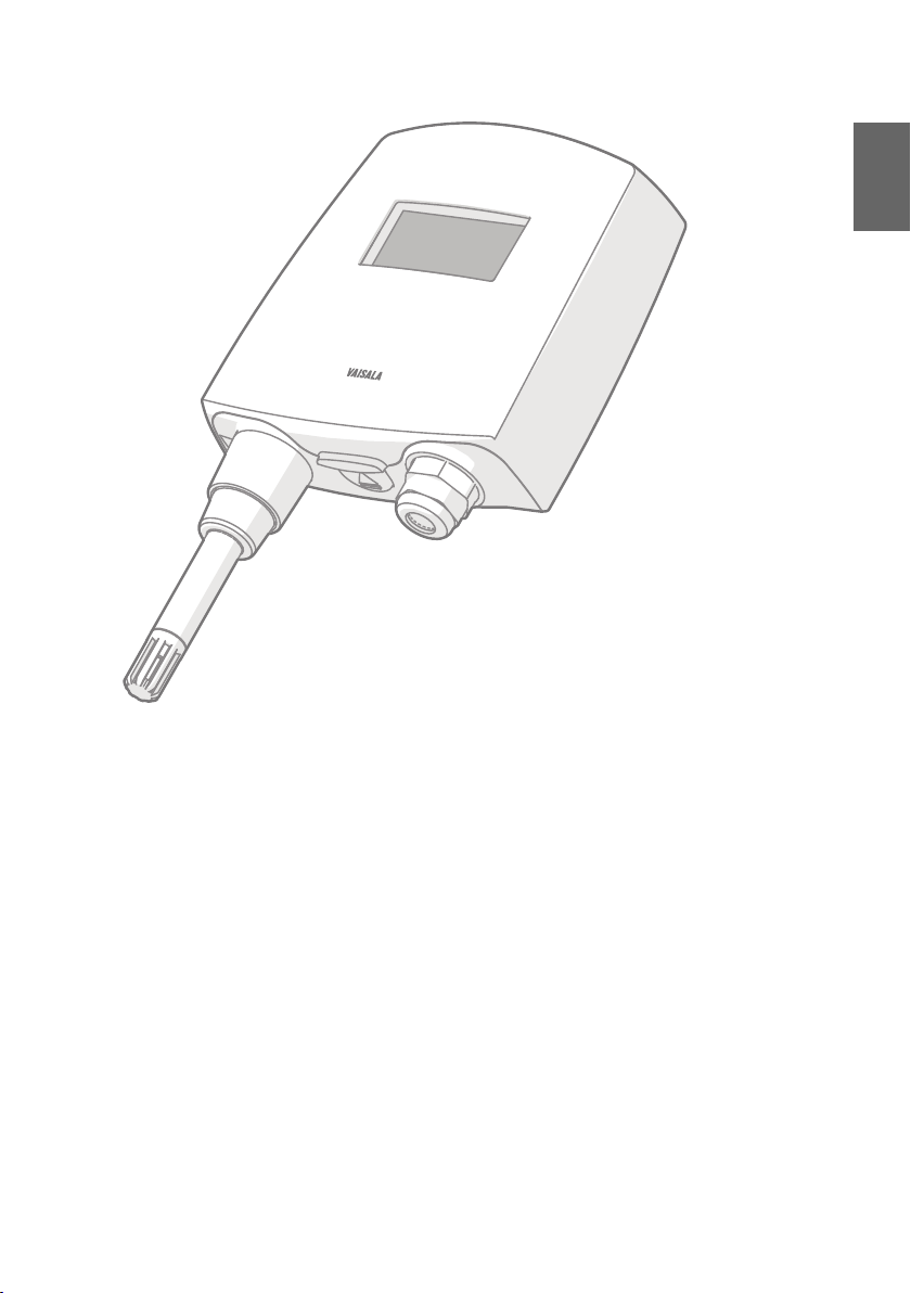
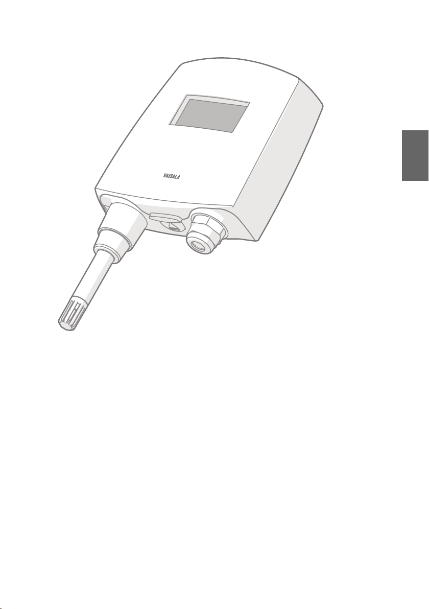
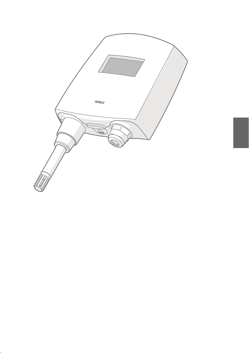
Vaisala HUMICAPâ Humidity and Temperature Transmitter Series HMT130 measures relative
humidity (RH) and temperature (T) and outputs the measurements to voltage outputs and
RS-485. Other quantities, such as dewpoint (Td), can be calculated from the basic RH and T
values according to the device configuration.
HMT130 is available either with a fixed probe directly attached to the transmitter housing, or
with a remote probe with dierent (3/5/10/20m) cable lengths.
The transmitter can also be ordered with an optional LCD display without backlight.
HMT130 is typically installed mounted on the wall with up to four screws (not included). Rain
and radiation shields and a duct installation kit are available as accessories. A drilling template
is available at the end of this guide to help you position the screws correctly.
5
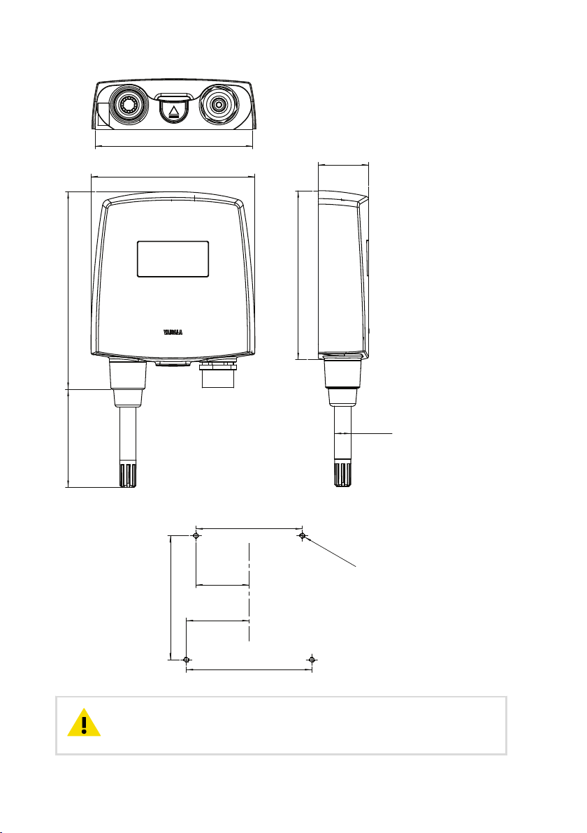
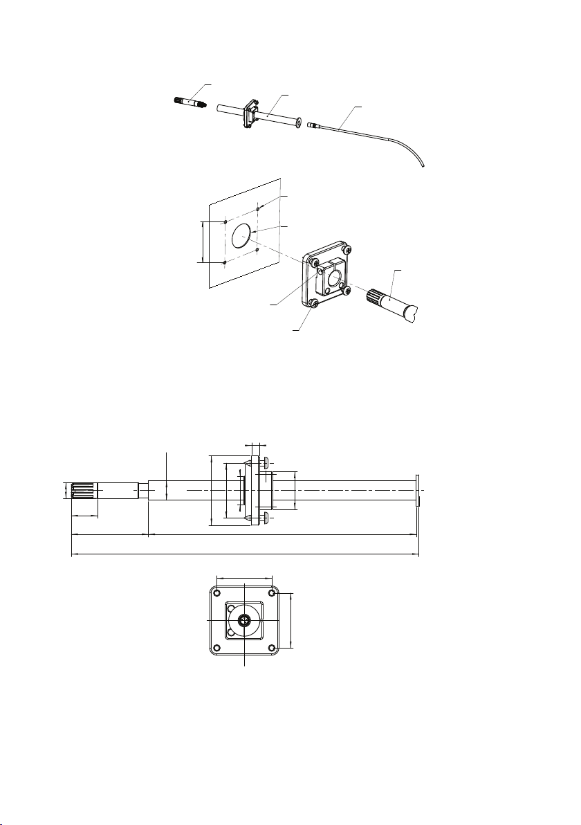
Dimensions
14572
120
37
124
Ø 12
116
46
39
M4
;
4 pcs
91
92
78
Wall Assembly Dimensions
CAUTION!
there is not much room between the upper fastening holes and the exposed
display component. Be particularly careful when using a cordless drill.
6 M211281EN-D
It is possible to damage the display when tightening the screws, as
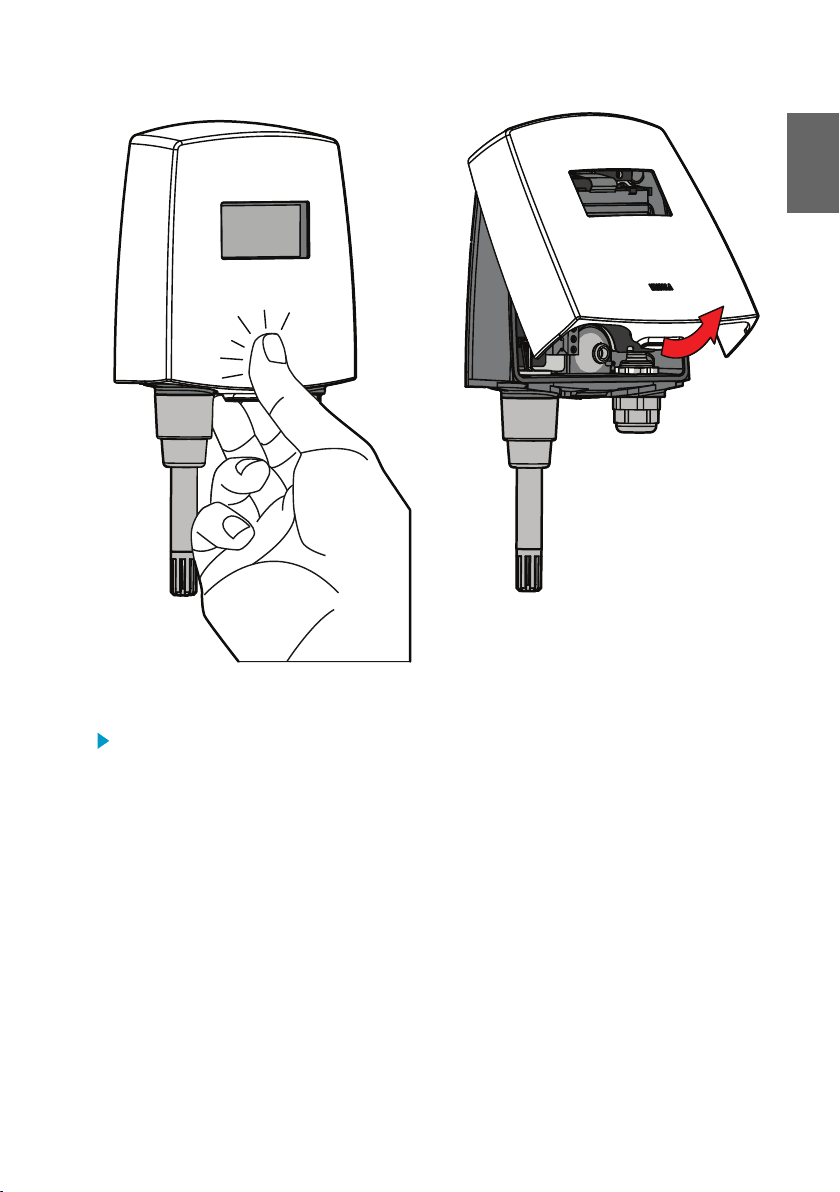
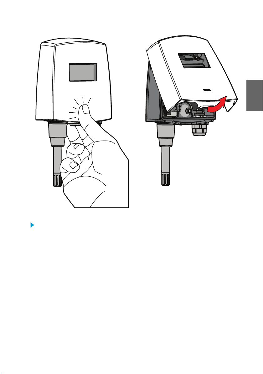
Opening the Transmitter Cover
ENGLISH
To open the transmitter cover:
1. If the transmitter is not mounted already, hold it against a
2. Push on the cover with your thumb, and pull the bottom part of the cover towards
yourself.
flat surface.
7
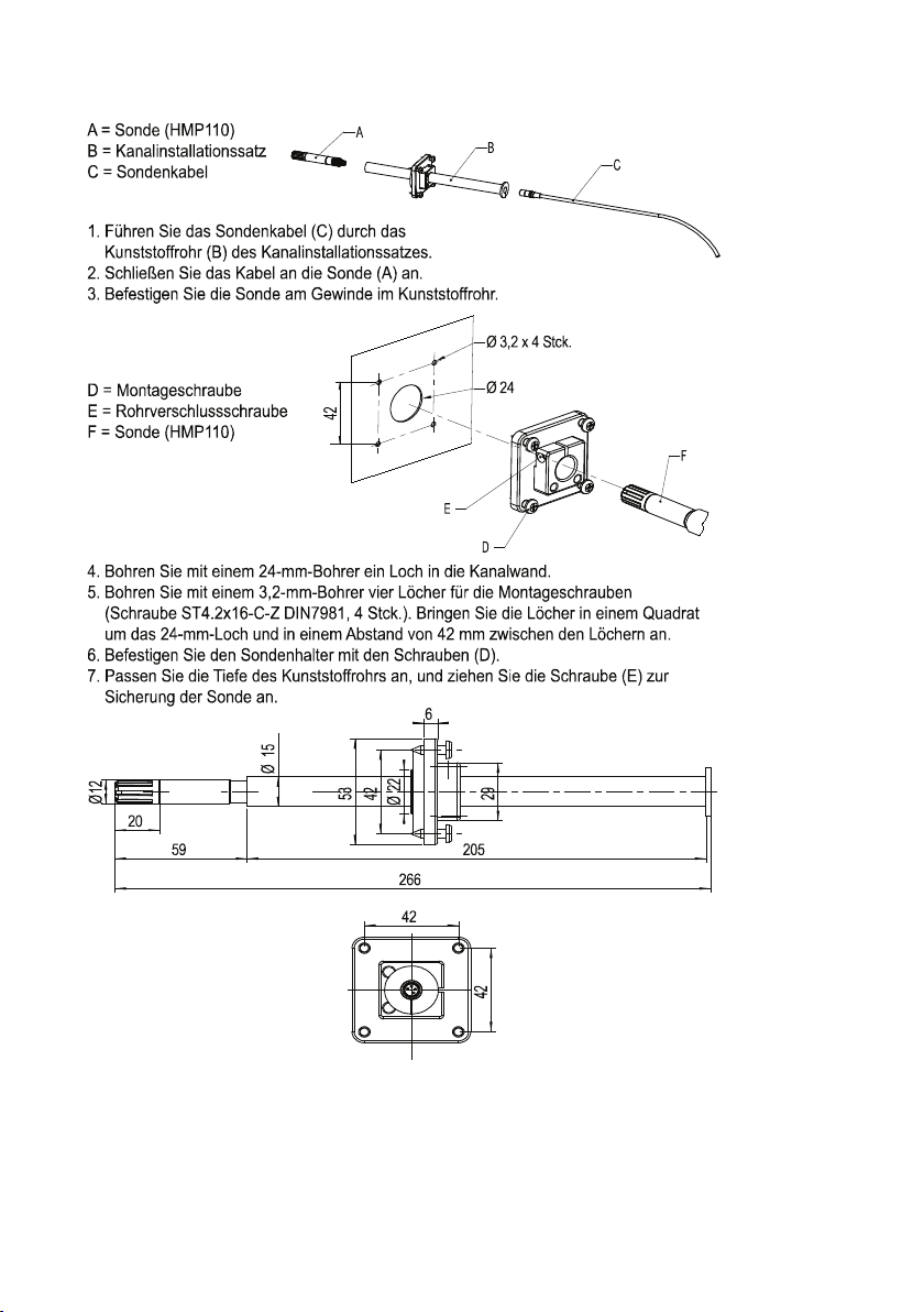
Duct Installation Kit
A = Probe (HMP110)
B = Duct installation kit
C = Probe Cable
1. Pass the probe cable through the plastic pipe of the duct installation kit.
2. Connect the probe cable to the HMP110.
3. Use a 24mm drill bit to make a hole in the duct wall.
4. Use a 3.2mm drill bit to make four holes for the installation screws
(ST4.2x16-C-Z DIN7981 screw, 4pcs). The holes should be arranged
in a square around the 24mm hole, at a distance of 42mm from each other.
5. Mount the probe holder using the screws (D).
6. Adjust the depth of the plastic pipe and tighten the screw (E) to lock the probe in place.
A
B
C
42
F
D
E
D = Installation screw
E = Pipe locking screw
F = Probe (HMP110)
Ø 24
Ø 3,2x 4 pcs
29
59
20
Ø 15
205
42
53
Ø 22
6
Ø12
266
42
42
8 M211281EN-D
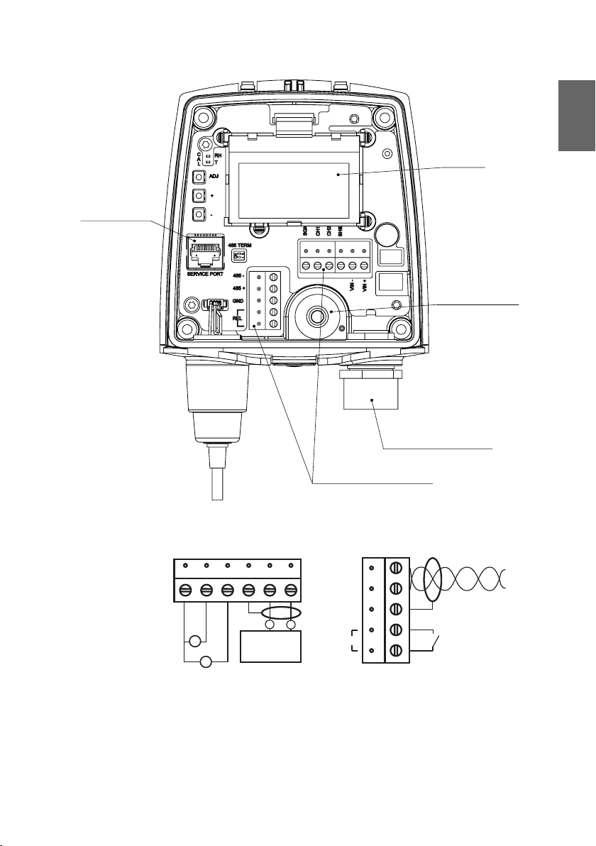
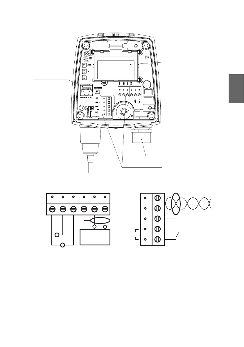
LCD
Display
Service port
Field wire terminals
2) Relay Connection
1) Power supply and voltage
V
10 ... 35 VDC*
24 VAC
+
-
485-
485+
GND
REL
Cable grommet
(rubber plug)
Cable bushing:
cable gland,
cable grommet,
or conduit fitting
* 15 ... 35 VDC with 0...10V output
V
V
Wiring
ENGLISH
9

Adjusting Humidity and Temperature with Push Buttons
The instructions here apply to both 1-point and 2-point calibration.
To make a humidity or temperature adjustment:
1. Open the transmitter cover. There are 3 buttons marked ADJ, + and - on the motherboard.
There are also two indicator LEDs, one green and one red.
2. Press the ADJ button and hold it down until the green indicator LED begins to blink slowly
(800ms cycle time).
3. The transmitter is now in RH calibration state. Analog output and optional display will still
follow the actual measured RH value.
If you do not wish to perform the RH adjustment at this time, press the ADJ
button one more time. The green indicator LED turns o and the red
indicator LED begins to blink slowly (800ms cycle time) to indicate T
calibration state. To calibrate T, follow the instructions starting from step 7.
4. Remove the filter and insert the probe into a measurement hole of the dry end reference
chamber (for example, LiCl: 11 % RH) to do the low humidity oset adjustment.
Do not touch the adjustment buttons before the conditions have stabilized.
This takes approximately 30 minutes.
5. Press either the - or + button at least once, make sure that the U
adjust using the - and + buttons if needed, and press the ADJ button again. The green
indicator LED begins to blink faster (400ms cycle time).
If you do not wish to perform the two-point RH adjustment at this time, press
the ADJ button one more time. The green indicator LED turns o and the red
indicator LED begins to blink slowly (800ms cycle time) to indicate T
calibration state. To calibrate T, follow the instructions starting from step 7.
If one-point calibration is done at more than 50% RH, a gain adjustment is
done instead of an oset adjustment.
6. Insert the probe into the high end reference chamber (for example, NaCl: 75 % RH
chamber in the humidity calibrator HMK15) and do the high humidity gain adjustment by
using the - and + buttons to make sure the U
- or + at least once even if the value is correct). To
button. The green LED is now turned
(800ms cycle time).
10 M211281EN-D
o and the red indicator LED begins to blink slowly
voltage is correct (you have to press either
out
finish the RH calibration, press the ADJ
voltage is correct,
out

7. The transmitter is now in T calibration state. Analog output and optional display will still
follow the actual measured T value.
If you do not wish to perform the T adjustment at this time, press ADJ button
one more time. The red indicator LED is turned o and the transmitter
returns to normal mode. The calibration procedure is now finished.
8. Insert the probe into a known reference temperature (if Vaisala Humidity Calibrator
HMK15 is not used) and let the temperature reading stabilize.
Do not touch the adjustment buttons before the conditions have stabilized.
9. Using the - and + buttons, make the temperature oset adjustment by making sure the
U
voltage is correct (you have to press either - or + at least once even if the value is
out
correct) and press the ADJ button. The red indicator LED begins to blink faster (400ms
cycle time).
If you do not wish to perform the two-point T adjustment at this time, press
the ADJ button one more time. The red indicator LED is turned o and the
transmitter returns to normal mode. The calibration procedure is now
finished.
10. Insert the probe into another reference temperature.
Do not touch the adjustment buttons before the conditions have stabilized.
ENGLISH
11. Using the - and + buttons, make the temperature gain adjustment by making sure the U
voltage is correct (you have to press either - or + at least once even if the value is correct).
12. Press the ADJ button one more time. The red indicator LED turns o and the transmitter
returns to normal mode. The calibration procedure is now finished.
In case of calibration error, both LEDs blink alternately at a very fast rate (cycle
time 200ms) for a period of 2s after which the transmitter returns to normal
mode.
out
11

If your transmitter has the optional display, the following notifications are shown
on the display during calibration:
• Probe cal: RH 1 (corresponding the green LED blinking slowly)
• Probe cal: RH 2 (corresponding the green LED blinking fast)
• Probe cal: T1 (corresponding the red LED blinking slowly)
• Probe cal: T2 (corresponding the red LED blinking fast)
• Probe cal: Error (corresponding both LEDs blinking alternately at very fast
rate)
12 M211281EN-D

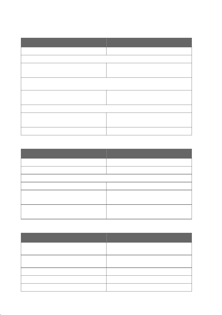
Troubleshooting
Table 1 Error Codes, Descriptions and Texts
Code Description Error Text
1 Probe T measurement error Probe T meas
2 Probe RH measurement error Probe RA meas
3 Probe communication error Probe communication
4 Probe checksum error Probe checksum
5 Probe message form error Probe message form
6 Program's flash checksum error Program code checksum
7 Current settings checksum
error (RAM)
8 Factory FLASH not initialised Factory defaults empty
9 User FLASH not initialised User defaults empty
10 Voltage is too low to operate
correctly
11 Measurements not available Measurements not available
12 Oscillator fault bit active HW fault 1
13 Analog output quantity invalid Analog output quantity invalid
14 Display quantity invalid Display quantity invalid
15 Invalid relay setting Relay quantity invalid
Settings checksum
Voltage too low
ENGLISH
13
Technical Data
Table 2 Relative Humidity Measurement Specifications
Property Description/Value
Measurement range 0 ... 100 %RH
Accuracy (including non-linearity, hysteresis, and repeatability) at 0 … +40 °C (+32 … +104 °F):
0 … 90 %RH
90 … 100 %RH
Accuracy (including non-linearity, hysteresis, and repeatability) at -40 … 0 °C, +40 … +80 °C
(-40 … 32 °F, 104 … 176 °F):
0 … 90 %RH
90 … 100 %RH
Factory calibration uncertainty at +20 °C (+68 °F):
0 … 90 %RH
90 … 100 %RH
Humidity sensor Vaisala HUMICAPâ 180R
Table 3 Temperature Measurement Specifications
Property Description/Value
Measurement range -40 … +80 °C (-40 … 176 °F)
Temperature sensor Pt1000 RTD Class F0.1 IEC 60751
Accuracy over temperature range:
At +15 … +25 °C (59 … 77 °F) ±0.2 °C (±0.36 °F)
At 0 … +15 °C and at +25 … +40 °C
(at 32 … 59 °F and at 77 … 104 °F)
At -40 … +0 °C and at +40 … +80 °C
(at -40 … 32 °F and at 104 … 176 °F)
±1.5 %RH
±2.5 %RH
±3.0 %RH
±4.0 %RH
±1.1 %RH
±1.8 %RH
±0.25 °C (±0.45 °F)
±0.4 °C (±0.72 °F)
Table 4 Operating Environment Specifications
Property Description/Value
Operating temperature of transmitter body, no
display
Operating temperature of transmitter body with
display
Operating temperature, HMP110 probe -40 … +80 °C (-40 … 176 °F)
Storage temperature -50 … +70 °C (-58 … 158 °F)
EMC compliance EN 61326-1 and EN 55022
14 M211281EN-D
-40 … +60 °C (-40 … 140 °F)
-20 … +60 °C (-4 … 140 °F)
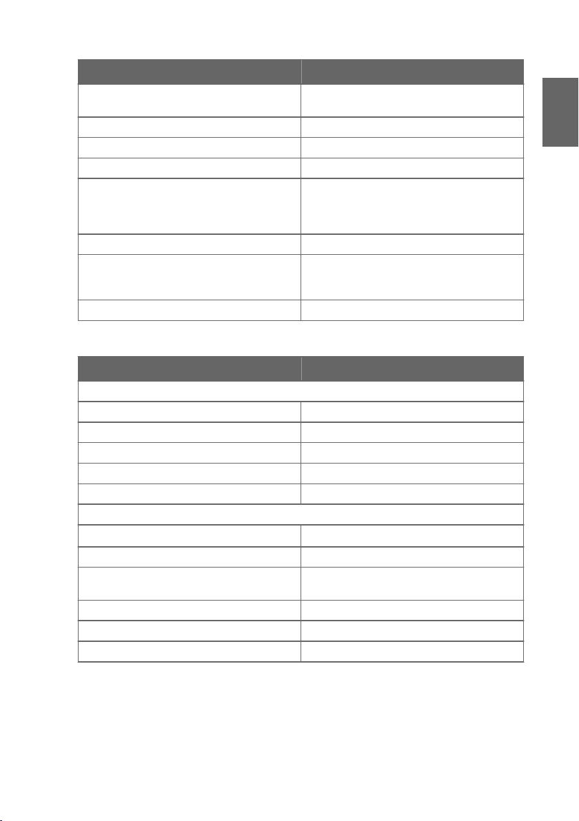
Table 5 Inputs and Outputs
Property Description/Value
Voltage output signals 0 … 1 V, 0 … 5 V, 0 … 10 V or user defined
between 0 … 10 V
Min output resistance 1 kΩ
Serial output RS-485, non-isolated
Relay output 1 relay (max. 50 VDC, 200 mA)
Supply voltage 10 … 35 VDC
15 … 35 VDC (when output 0 … 10 V)
24 VAC (±20 %)
Current consumption at 24 VDC 8 mA, if relay closed 15 mA
Max. additional error caused by the analog
±0.1 % of FS output signal
outputs after calibration at +20 °C (68 °F)
ambient temperature
Temperature dependence of the analog outputs ±0.005 % of FS output signal
Table 6 Mechanical Specifications
Property Description/Value
Material
Transmitter housing PBT plastic
Display window PC plastic
Probe body Stainless steel (AISI 316)
Probe grid filter Chrome coated ABS plastic
IP rating IP65
Connections
Inputs and outputs
Screw terminals 0.5 … 1.5 mm
2
Probe interface 4-pin M8 female panel connector
Probe cable lengths 3 m, 5 m, 10 m, 20 m: cables can be cascaded up
to 50 m
Display (optional) LCD display without backlight
Weight (wall model, including probe) 270 g
Weight (10 m cable model) 540 g
ENGLISH
15

Warranty
For standard warranty terms and conditions, see www.vaisala.com/warranty.
Please observe that any such warranty may not be valid in case of damage due to normal wear
and tear, exceptional operating conditions, negligent handling or installation, or unauthorized
modifications. Please see the applicable supply contract or Conditions of Sale for details of the
warranty for each product.
Technical Support
Contact Vaisala technical support at helpdesk@vaisala.com. Provide at least the
following supporting information:
• Product name, model, and serial number
• Name and location of the installation site
• Name and contact information of a technical person who can provide further
information on the problem
For more information, see www.vaisala.com/support.
Recycling
Recycle all applicable material.
Follow the statutory regulations for disposing of the product and packaging.
16 M211281EN-D
Produktübersicht
DEUTSCH
Der Vaisala HUMICAPâ Feuchte- und Temperaturmesswertgeber der Serie HMT130 misst die
relative Luftfeuchte und/oder die Temperatur und gibt die Messwerte über
Spannungsausgänge und den RS-485-Ausgang aus. Andere Größen wie der Taupunkt (Td)
können je nach
Der HMT130 ist wahlweise mit einer direkt am Messwertgebergehäuse befestigten Sonde oder
mit einer dezentralen Sonde mit unterschiedlichen Kabellängen (3/5/10/20 m) erhältlich.
Für den HMT130 steht auch eine optionale LCD-Anzeige ohne Hintergrundbeleuchtung zur
Verfügung.
Der HMT130 wird in der Regel mit bis zu vier Schrauben (nicht im Lieferumfang enthalten) an
der Wand montiert. Ein Regen- und Strahlungsschutzgehäuse und ein Kanalinstallationssatz
sind als Zubehör erhältlich. Die Bohrschablone auf der hinteren Umschlaginnenseite dieses
Handbuchs hilft Ihnen bei der korrekten Positionierung der Schrauben.
Gerätekonfiguration über die Basiswerte für rF und T berechnet werden.
17

Abmessungen
14572
120
37
124
Ø 12
116
46
39
M4
;
4 st
ck.
91
92
78
Abmessungen für die Wandmontage
ACHTUNG
werden, weil zwischen den oberen Bohrungen und der freiliegenden
Anzeigekomponente nur wenig Platz ist. Seien Sie besonders vorsichtig, wenn
Sie mit einem Akkuschrauber arbeiten.
18 M211281EN-D
Die Anzeige kann beim Festziehen der Schrauben beschädigt
Abdeckung das Messwertgebers önen
DEUTSCH
1. Wenn der Messwertgeber noch nicht montiert ist, halten Sie ihn gegen eine ebene Fläche.
2. Drücken Sie mit dem Daumen auf die Abdeckung und ziehen Sie den unteren Teil der
Abdeckung zu sich.
19
Kanalinstallationssatz
20 M211281EN-D
LCD-Anzeige
Serviceschnittstelle
Leiterklemmen
2) Relaisanschluss
1) Stromversorgung
und Spannung
V
V
10 ... 35 VDC*
24 VAC
+
-
485-
485+
GND
REL
Durchführungstülle
(Gummistopfen)
Kabelverschraubung:
Kabelverschraubung,
Durchführungstülle oder
Rohrverschraubung
* 15 ... 35 V DC mit 0...10V Ausgang
Verdrahtung
DEUTSCH
21

Justierung von Feuchte und Temperatur
So können Sie die Feuchte oder Temperatur justieren (die Anweisungen gelten gleichermaßen
für die Ein-Punkt- und die Zwei-Punkt-Justierung):
1. Önen Sie die Abdeckung des Messwertgebers. Die drei Tasten mit den Symbolen ADJ, +
und – sind nun zu sehen. Es gibt außerdem eine grüne und eine rote LED auf der HMT130Hauptplatine.
2. Drücken Sie die Taste ADJ und halten Sie sie gedrückt, bis die grüne LED langsam blinkt
(Zykluszeit: 800 ms).
3. Der HMT130-Messwertgeber befindet sich jetzt im rF-Kalibrierungsmodus. Über den
Analogausgang und die optionale Anzeige wird weiterhin der tatsächlich gemessene rFWert ausgegeben.
Wenn Sie an dieser Stelle keine rF-Justierung vornehmen möchten, drücken
Sie erneut die Taste ADJ. Die grüne LED wird ausgeschaltet und die rote LED
blinkt langsam (Zykluszeit: 800 ms), um zu melden, dass der TKalibrierungsmodus aktiviert wurde. Nun können Sie mit den Anweisungen
ab Schritt 7 fortfahren.
4. Entfernen Sie den Filter, und führen Sie die Sonde in eine Kalibrierönung der
Referenzkammer für den niedrigsten Wert ein (z. B. LiCl: 11 % rF), um die Justierung des
Oset für den niedrigsten Wert vorzunehmen.
Betätigen Sie die Justierungstasten erst, wenn sich die Bedingungen
stabilisiert haben. Dies wird etwa 30 Minuten in Anspruch nehmen.
5. Drücken Sie mindestens einmal die Taste – oder +, stellen Sie sicher, dass der Spannung
UAusg. korrekt ist, nehmen Sie gegebenenfalls über die Tasten – und + eine Justierung vor
und drücken Sie erneut die Taste ADJ. Die grüne LED blinkt jetzt schneller (Zykluszeit:
400 ms).
Wenn Sie an dieser Stelle keine Zwei-Punkt-rF-Justierung vornehmen
möchten, drücken Sie erneut die Taste ADJ. Die grüne LED wird
ausgeschaltet und die rote LED blinkt langsam (Zykluszeit: 800 ms), um zu
melden, dass der T-Kalibrierungsmodus aktiviert wurde. Nun können Sie mit
den Anweisungen ab Schritt 7 fortfahren.
Wenn die Ein-Punkt-Kalibrierung bei einer rF von mehr als 50 %
vorgenommen wird, wird nicht der Oset, sondern der Verstärkungsfaktor
eingestellt.
6. Führen Sie die Sonde in die obere Referenzkammer (z. B. NaCl: 75 % rF im
Feuchtekalibrator HMK15) ein und stellen Sie über die Tasten – und + den
Verstärkungsfaktor der Feuchtemessung ein, sodass der Spannung UAusg. korrekt ist. (Sie
müssen mindestens einmal – oder + drücken, auch wenn der Wert korrekt ist.) Um die rFKalibrierung zu beenden, drücken Sie die Taste ADJ. Die grüne LED wird jetzt
ausgeschaltet und die rote LED blinkt langsam (Zykluszeit: 800 ms).
22 M211281EN-D

7. Der HMT130-Messwertgeber befindet sich jetzt im T-Kalibrierungsmodus. Über den
Analogausgang und die optionale Anzeige wird weiterhin der tatsächlich gemessene TWert ausgegeben.
Wenn Sie an dieser Stelle keine T-Justierung vornehmen möchten, drücken
Sie erneut die Taste ADJ. Die rote LED wird ausgeschaltet, und der
Messwertgeber kehrt in den normalen Modus zurück. Der
Kalibrierungsvorgang ist jetzt beendet.
8. Führen Sie die Sonde in eine Referenzkammer mit bekannter Temperatur (wenn der
HMK15-Feuchtekalibrator nicht verwendet wird) ein und warten Sie, bis sich der Messwert
stabilisiert hat.
Betätigen Sie die Justierungstasten erst, wenn sich die Bedingungen
stabilisiert haben.
9. Stellen Sie über die Tasten
– und + den
Temperatur-Oset ein, sodass der Spannung
UAusg. korrekt ist. (Sie müssen mindestens einmal – oder + drücken, auch wenn der Wert
korrekt ist.) Drücken Sie dann die Taste ADJ. Die rote LED blinkt jetzt schneller
(Zykluszeit: 400 ms).
Wenn Sie an dieser Stelle keine Zwei-Punkt-T-Justierung vornehmen
möchten, drücken Sie erneut die Taste ADJ. Die rote LED wird ausgeschaltet,
und der Messwertgeber kehrt in den normalen Modus zurück. Der
Kalibrierungsvorgang ist jetzt beendet.
10. Führen Sie die Sonde in eine andere Referenztemperaturkammer ein.
Betätigen Sie die Justierungstasten erst, wenn sich die Bedingungen
stabilisiert haben.
11. Stellen Sie über die Tasten – und + den Temperatur-Verstärkungsfaktor ein, sodass der
Spannung UAusg. korrekt ist. (Sie müssen mindestens einmal – oder + drücken, auch
wenn der Wert korrekt ist.)
12. Drücken Sie erneut die Taste ADJ. Die rote LED wird ausgeschaltet, und der
Messwertgeber kehrt in den normalen Modus zurück. Der Kalibrierungsvorgang ist jetzt
beendet.
DEUTSCH
Bei einem Kalibrierungsfehler blinken beide LEDs 2 Sekunden lang abwechselnd
sehr schnell (Zykluszeit: 200 ms). Anschließend kehrt der Messwertgeber in den
normalen Modus zurück.
23

Bei Verwendung eines HMT130-Messwertgebers mit Anzeigeoption werden
während der Kalibrierung folgende Meldungen auf der Anzeige angezeigt:
• Probe cal: RH 1 entspricht dem langsamen Blinken der grünen LED
• Probe cal: RH 2 entspricht dem schnellen Blinken der grünen LED
• Probe cal: T1 entspricht dem langsamen Blinken der roten LED
• Probe cal: T2 entspricht dem schnellen Blinken der roten LED
• Probe cal: Error entspricht dem sehr schnellen abwechselnden Blinken beider
LEDs
24 M211281EN-D

Fehlerbeseitigung
Tabelle 7 Fehlercodes und -meldungen
Code Beschreibung Fehlermeldung
1 Messungsfehler der T-Sonde Probe T meas
2 Messungsfehler der rF-Sonde Probe RA meas
3 Kommunikationsfehler der Sonde Probe communication
4 Prüfsummenfehler der Sonde Probe checksum
5 Fehler der Sondenmeldungsform Probe message form
6 Programm-Flash – Prüfsummenfehler Program code checksum
7 Prüfsummenfehler der aktuellen Ein-
stellungen (RAM)
8 Werks-Flash nicht initialisiert Factory defaults empty
9 Benutzer-Flash nicht initialisiert User defaults empty
10 Spannung für korrekten Betrieb zu
niedrig
11 Messwerte nicht verfügbar Measurements not available
12 Oszillator-Fehlerbit aktiv HW fault 1
13 Ungültige Analogausgangsgröße Analog output quantity invalid
14 Ungültige Anzeigegröße Display quantity invalid
15 Ungültige Relaisgröße Relay quantity invalid
Settings checksum
Voltage too low
DEUTSCH
25
Technische Daten
Tabelle 8 Spezifikationen für die Messung der relativen Luftfeuchte
Eigenschaft Beschreibung/Wert
Messbereich 0 bis 100 % rF
Genauigkeit (einschl. Nichtlinearität, Hysterese und Wiederholbarkeit) bei 0 bis +40 °C (+32 bis
+104 °F):
0 bis 90 % rF
90 bis 100 % rF
Genauigkeit (einschl. Nichtlinearität, Hysterese und Wiederholbarkeit) bei -40 bis 0 °C und +40 bis
+80 °C (-40 bis +32 °F und +104 bis +176 °F):
0 bis 90 % rF
90 … 100 %RH
Unsicherheit der Werkskalibrierung bei 20 °C (+68 °F):
0 … 90 % rF
90 … 100 % rF
Luftfeuchtesensor Vaisala HUMICAPâ 180R
Tabelle 9 Temperature Measurement Specifications
Eigenschaft Beschreibung/Wert
Messbereich -40 … +80 °C (-40 … 176 °F)
Temperatursensor Pt1000 RTD Klasse F0.1 IEC 60751
Genauigkeit über Temperaturbereich:
bei +15 bis +25 °C (+59 bis +77 °F) ±0.2 °C (±0.36 °F)
bei 0 bis +15 °C und +25 bis +40 °C
(+32 bis +59 °F und +77 bis +104 °F)
bei -40 bis 0 °C und +40 bis +80 °C
(-40 bis +32 °F und +104 bis +176 °F)
±1,5 % rF
±2,5 % rF
±3,0 % rF
±4,0 % rF
±1.1 % rF
±1.8 % rF
±0.25 °C (±0.45 °F)
±0.4 °C (±0.72 °F)
Tabelle 10 Spezifikationen für die Betriebsumgebung
Eigenschaft Beschreibung/Wert
Betriebstemperaturbereich, Messwertgebergehäuse ohne Anzeige
Betriebstemperaturbereich, Messwertgebergehäuse mit Anzeige
Betriebstemperaturbereich, Operating temperature, HMP110 probe
26 M211281EN-D
-40 bis +60 °C (-40 bis +140 °F)
-20 bis +60 °C (-4 bis +140 °F)
-40 bis +80 °C (-40 bis +176 °F)
Eigenschaft Beschreibung/Wert
Lagertemperaturbereich -50 bis +70 °C (-58 bis +158 °F)
Elektromagnetische Verträglichkeit (EMV) EN 61326-1, EN 55022
Tabelle 11 Ein- und Ausgänge
Eigenschaft Beschreibung/Wert
Ausgangssignal 0 … 1 V, 0 … 5 V, 0 … 10 V, Benutzerdefiniert zwi-
schen 0 ... 10 V
Min. Ausgangswiderstand 1 kΩ
Serieller Ausgang RS-485, (nicht isoliert)
Relaisausgang 1 Relais (max. 50 V DC, 200 mA)
Versorgungsspannung 10 … 35 VDC
15 … 35 VDC (wenn Ausgang: 0 ... 10 V)
24 VAC (±20 %)
Max. zusätzlicher Fehler durch Analogausgänge
±0,1 % des Ausgangsstroms v. Ew.
nach der Kalibrierung bei einer Umgebungstemperatur von +20 °C
Temperaturabhängigkeit des Analogausgangs ±0,005 %/°C des Ausgangsstroms v. Ew.
Tabelle 12 Mechanikspezifikationen
Eigenschaft Beschreibung/Wert
Material
Messwertgebergehäuse PBT-Kunststo
Anzeigefenster PC-Kunststo
Sondenkörper Edelstahl (AISI 316)
Sondengitterfilter Verchromter ABS-Kunststo
Gehäuseschutzart IP65
Anschlüsse
Stromschleifenausgänge
Schraubklemmen 0,5 bis 1.5 mm
2
Sondenschnittstelle 4-polige Steckerbuchse M8
Sondenkabellängen 3 m, 5 m, 10 m, 20 m Kabel können bis zu 50 m
lang in Kaskade geschaltet werden
Anzeige (optional) LCD-Anzeige ohne Hintergrundbeleuchtung
Gewicht (Wandmodell, einschließlich Sonde) 270 g
Gewicht (Modell mit 10-m-Kabel) 540 g
DEUTSCH
27

Gewährleistung
Unsere Standardgarantiebedingungen finden Sie unter www.vaisala.com/warranty.
Diese Garantie deckt keine Verschleißschäden, Schäden infolge außergewöhnlicher
Betriebsbedingungen, Schäden infolge unzulässiger Verwendung oder Montage oder Schäden
infolge nicht genehmigter
bestimmte Produkte enthalten der zugehörige Liefervertrag und die Verkaufsbedingungen.
Modifikationen ab. Einzelheiten zum Gewährleistungsumfang für
Technischer Support
Wenden Sie sich an den technischen Support von Vaisala unter
helpdesk@vaisala.com. Geben Sie mindestens folgende Informationen an:
• Produktname, Modell und Seriennummer
• Name und Standort der Installation
• Name und Kontaktinformationen eines Technikers für weitere Auskünfte
Weitere Informationen
finden Sie unter www.vaisala.com/support.
Recycling
Recyceln Sie alle wiederverwertbaren Materialien.
Beachten Sie bei der Entsorgung von Produkten und Verpackung die gesetzlichen
Regelungen.
28 M211281EN-D
Présentation du produit
FRANÇAIS
Le transmetteur d'humidité et de température Vaisala HUMICAPâ de la série HMT130 permet
de mesurer l'humidité relative et/ou la température, puis de transmettre les mesures aux
sorties de tension et RS‑485. Les autres valeurs, comme le point de rosée (Td), peuvent être
calculées à partir des valeurs HR et T de base, selon la
Le HMT130 est disponible soit avec une sonde fixée directement sur le boîtier du transmetteur,
soit avec une sonde distante munie de câbles de diérentes longueurs (3/5/10/20 m).
Le HMT130 est également disponible avec un écran LCD sans rétroéclairage (en option).
Le HMT130 est en général
protection contre la pluie, un bouclier anti-rayonnement et un kit d’installation sur gaine sont
également disponibles en accessoires. A l’intérieur de la quatrième de couverture de ce guide,
vous trouverez un gabarit de perçage qui vous permettra de placer correctement les vis.
fixé au mur à l’aide de quatre vis (non fournies). Un système de
configuration de l'appareil.
29

Dimensions
14572
120
37
124
Ø 12
116
46
39
M4
; 4 pi
è
c
e
s
91
92
78
Dimensions du dispositif de montage mural
ATTENTION
car l'espace entre les trous de fixation supérieurs et la partie exposée de l'écran
est réduit. Faites particulièrement attention si vous utilisez une visseuse sans fil.
30 M211281EN-D
Il existe un risque d'endommager l'écran lors du serrage des vis
 Loading...