

Page 1
M211488EN-H
User Guide
Vaisala Wi-Fi Data Logger
HMT140
Page 2

PUBLISHED BY
Vaisala Oyj
Vanha Nurmijärventie 21, FI-01670 Vantaa, Finland
P.O. Box 26, FI-00421 Helsinki, Finland
+358 9 8949 1
Visit our Internet pages at www.vaisala.com.
© Vaisala Oyj 2019
No part of this document may be
reproduced, published or publicly
displayed in any form or by any means,
electronic or mechanical (including
photocopying), nor may its contents be
modified, translated, adapted, sold or
disclosed to a third party without prior
written permission of the copyright holder.
Translated documents and translated
portions of multilingual documents are
based on the original English versions. In
ambiguous cases, the English versions are
applicable, not the translations.
The contents of this document are subject
to change without prior notice.
Local rules and regulations may vary and
they shall take precedence over the
information contained in this document.
Vaisala makes no representations on this
document’s compliance with the local
rules and regulations applicable at any
given time, and hereby disclaims any and
all responsibilities related thereto.
This document does not create any legally
binding obligations for Vaisala towards
customers or end users. All legally binding
obligations and agreements are included
exclusively in the applicable supply
contract or the General Conditions of Sale
and General Conditions of Service of
Vaisala.
This product contains software developed
by Vaisala or third parties. Use of the
software is governed by license terms and
conditions included in the applicable
supply contract or, in the absence of
separate license terms and conditions, by
the General License Conditions of Vaisala
Group.
This product may contain open source
software (OSS) components. In the event
this product contains OSS components,
then such OSS is governed by the terms
and conditions of the applicable OSS
licenses, and you are bound by the terms
and conditions of such licenses in
connection with your use and distribution
of the OSS in this product. Applicable OSS
licenses are included in the product itself
or provided to you on any other applicable
media, depending on each individual
product and the product items delivered
to you.
Page 3

Table of Contents
Table of Contents
1. About This Document................................................................................... 7
1.1 Version Information..........................................................................................7
1.2 Related Manuals................................................................................................ 7
1.3 Documentation Conventions...........................................................................7
1.4 Trademarks........................................................................................................ 8
2. Product Overview...........................................................................................9
2.1 Overview of HMT140 Features........................................................................ 9
2.1.1 Data Management..................................................................................... 9
2.1.2 Models.........................................................................................................9
2.1.3 Options and Accessories.........................................................................10
2.1.4 Fixed or Remote Probe...........................................................................10
2.1.5 Interchangeable Probe............................................................................10
2.1.6 Optional Display........................................................................................ 11
2.2 HMT140 Components......................................................................................12
2.2.1 Installation Kit........................................................................................... 12
2.2.2 HMT140 Utility and Configuration Cable............................................... 13
2.2.3 Connections and Wiring..........................................................................14
2.3 Safety................................................................................................................16
2.3.1 ESD Protection..........................................................................................17
2.4 Regulatory Compliances.................................................................................17
2.4.1 FCC Compliance Statement....................................................................18
2.4.2 ISED Compliance Statement...................................................................18
3. Installation........................................................................................................19
3.1 Mounting...........................................................................................................19
3.1.1 Opening Data Logger Cover...................................................................19
3.1.2 Wall Mounting......................................................................................... 20
3.1.3 Duct Installation.......................................................................................22
3.1.4 Probe Assembly with Duct Installation Kit...........................................22
3.2 Optional Mounting Accessories....................................................................24
3.2.1 Probe Mounting Flange.......................................................................... 24
3.2.2 Probe Mounting Clamp...........................................................................24
4. Set Up and Operation................................................................................. 25
4.1 Connect and Configure.................................................................................. 25
4.1.1 Installing HMT140 Utility Software........................................................25
4.1.2 Setting up HMT140 Hardware................................................................25
4.1.3 Configuring the HMT140 to Your Network...........................................26
4.1.4 Setup Consideration............................................................................... 28
4.2 Custom Settings............................................................................................. 28
4.2.1 Modify Transmission Settings................................................................ 28
4.2.2 Modify HMT140 Description....................................................................31
4.2.3 Check Transmission Status......................................................................31
1
Page 4

HMT140 User Guide M211488EN-H
4.3 HMT140 Function Modes...............................................................................33
4.3.1 Operating Modes..................................................................................... 33
4.3.2 Transmission of Data.............................................................................. 34
4.3.3 Transmit Attempts.................................................................................. 34
4.3.4 Alarm-Triggered Transmission.............................................................. 34
4.4 Additional Settings.........................................................................................35
4.4.1 Change Input/Output Scale...................................................................35
4.4.2 Save and Recall Settings........................................................................36
4.4.3 Delete Saved Settings.............................................................................36
4.4.4 Restart the HMT140................................................................................ 36
4.4.5 Get General Information.........................................................................36
4.5 Battery Usage................................................................................................. 36
4.5.1 Viewing Battery Life Remaining............................................................36
4.5.2 Units and Temperature........................................................................... 37
4.5.3 Connection Performance....................................................................... 38
4.6 Advanced Options..........................................................................................39
4.6.1 Passwords................................................................................................40
4.6.2 Set Up a New Channel............................................................................. 41
4.6.3 Find Additional Networks....................................................................... 41
4.6.4 Test Network Connectivity.....................................................................43
4.7 Additional Program Parameters...................................................................43
5. Maintenance....................................................................................................45
5.1 Improving Sensor Response Time................................................................45
5.2 Removing and Fastening Probes..................................................................45
5.2.1 Fixed Probe Model.................................................................................. 45
5.2.2 Remote Probe Model..............................................................................46
5.3 Calibration and Adjustment..........................................................................47
5.4 Battery Replacement.....................................................................................48
6. Troubleshooting............................................................................................49
6.1 HMT140 Operation Mode.............................................................................. 49
6.2 Signal Strength............................................................................................... 49
6.3 Indicator Lights...............................................................................................49
6.4 Access Points..................................................................................................49
6.5 Transmit Cycle................................................................................................ 50
6.6 Frequently Asked Questions........................................................................ 50
7. Technical Data................................................................................................54
7.1 HMT140 Dimensions (Fixed Probe)..............................................................54
7.2 HMT140 Dimensions (Remote Probe)..........................................................55
7.3 HMT140 Specifications...................................................................................56
Index...................................................................................................................63
Warranty............................................................................................................65
Technical Support........................................................................................... 65
2
Page 5

Table of Contents
Recycling...........................................................................................................65
3
Page 6

HMT140 User Guide M211488EN-H
List of Figures
Figure 1 HMT140 Features.............................................................................................. 12
Figure 2 HMT140 Components Diagram.....................................................................14
Figure 3 RTD Wiring Diagram........................................................................................15
Figure 4 RTD and Boolean Wiring Diagram...............................................................15
Figure 5 Boolean Wiring Diagram.................................................................................15
Figure 6 Voltage Wiring Diagram................................................................................. 16
Figure 7 Current Wiring Diagram..................................................................................16
Figure 8 Opening Data Logger Cover..........................................................................19
Figure 9 Mounting Diagram............................................................................................21
Figure 10 Probe Installation with Duct Installation Kit.............................................22
Figure 11 Dimensions of HMP110 Probe with Duct Installation Kit....................... 23
Figure 12 Optional Probe Mounting Flange................................................................ 24
Figure 13 Optional Probe Mounting Clamp.................................................................24
Figure 14 Fixed Probe Model...........................................................................................46
Figure 15 Remote Probe Model...................................................................................... 47
Figure 16 HMT140 Fixed Probe Dimensions in mm (in)...........................................54
Figure 17 HMT140 Remote Probe Dimensions in mm (in)...................................... 55
4
Page 7

List of Tables
Table 1 Document Versions (English)............................................................................7
Table 2 Related Manuals....................................................................................................7
Table 3 Connect Time Components ............................................................................38
Table 4 HUMICAP Humidity and Temperature Probe HMP110..............................56
Table 5 Temperature Probes..........................................................................................56
Table 6 Analog Inputs...................................................................................................... 57
Table 7 Measurement Variants......................................................................................57
Table 8 Operating Environment....................................................................................58
Table 9 General Specifications...................................................................................... 58
Table 10 Mechanical Specifications............................................................................... 58
Table 11 Wireless................................................................................................................ 59
Table 12 Standards and Approvals................................................................................ 59
Table 13 Spare Parts and Accessories.......................................................................... 60
List of Tables
5
Page 8

HMT140 User Guide M211488EN-H
6
Page 9
Chapter 1 – About This Document
1. About This Document
1.1 Version Information
This document provides information for installing, operating, and maintaining the Vaisala Wi-Fi
Data Logger HMT140. It also details the operation of the Vaisala HMT140 Utility software.
Table 1 Document Versions (English)
Document Code Date Description
M211488EN-H July 2019 Updated section Regulatory Compliances (page 17) and the
M211488EN-G April 2019 New document template. Added sections Regional Versions
1.2 Related Manuals
Table 2 Related Manuals
Document Code Name
M211484EN Vaisala Wi-Fi Data Logger HMT140 Quick Guide
M211975EN Vaisala viewLinc Enterprise Server Version 5.0 User Guide
references to standards and approvals in section HMT140
Specifications (page 56).
(page 10), FCC Compliance Statement (page 18), and ISED
Compliance Statement (page 18). Updated power supply
specifications and section HMT140 Specifications (page 56).
1.3 Documentation Conventions
WARNING!
follow instructions carefully at this point, there is a risk of injury or even death.
CAUTION!
follow instructions carefully at this point, the product could be damaged or
important data could be lost.
Warning alerts you to a serious hazard. If you do not read and
Caution warns you of a potential hazard. If you do not read and
7
Page 10
HMT140 User Guide M211488EN-H
Note highlights important information on using the product.
Tip gives information for using the product more eciently.
Lists tools needed to perform the task.
Indicates that you need to take some notes during the task.
1.4 Trademarks
Vaisalaâ and HUMICAPâ are registered trademarks of Vaisala Oyj.
All other product or company names that may be mentioned in this publication are trade
names, trademarks, or registered trademarks of their respective owners.
8
Page 11

Chapter 2 – Product Overview
2. Product Overview
2.1 Overview of HMT140 Features
The Vaisala Wi-Fi Data Logger HMT140 measures relative humidity and temperature using the
connected probe and analog signals – RTD, Voltage, Current Loops and Boolean Contacts. The
HMT140 comes with or without an optional LCD display.
The HMT140 supports several dierent signal measurements (channels), which are monitored
in Vaisala viewLinc Enterprise Server software:
• Relative Humidity (RH)
• Temperature (T)
• Switch Contact
• Voltage and Current
Channel types are set at the factory during the time of order. Other wireless parameters can be
changed at a later date using an HMT140 Configuration Cable and Vaisala HMT140 Utility
software.
More Information
‣
Options and Accessories (page 10)
2.1.1 Data Management
An HMT140 can store several thousands of records before needing to overwrite data. In the
event of a communication problem, the HMT140 will continue to log and store data until it has
collected 3060 records per channel and then it will begin overwriting data.
For example, if an HMT140 is configured with a 5-minute sample rate, it will continue to log
data for approximately 10 days before overwriting data.
2.1.2 Models
The following HMT140 models and options are available:
• HMT141: Vaisala HUMICAPâ Humidity and Temperature Probe (RH/T)
• HMT143: Dual RTD Temperature Inputs w/5 m Probes (-90 to +90 °C (-130 to +194 °F))
• HMT144: Voltage Inputs (0 ... 5 VDC)
• HMT145: Voltage inputs (0 ... 10 VDC)
• HMT146: Current Inputs (0 ... 20 mA)
• HMT147: Boolean Inputs
• HMT148: RTD Temperature Input w/5 m Probe and Boolean Input
• HMT14C: RTD Inputs (customer-supplied Probe)
• HMT14D: RTD and Current Input
• HMT14E: RTD and Voltage Input (0 ... 5 VDC)
• HMT14F: RTD and Voltage Input (0 ... 10VDC)
9
Page 12

HMT140 User Guide M211488EN-H
2.1.2.1 Regional Versions
There are 2 regional versions of each HMT140 model, with dierent applicable standards and
regulations. The versions are distinguished by the letters A (for EU countries) and N (for nonEU countries) on the HMT140 Order Form.
For more information, see Table 12 (page 59).
2.1.3 Options and Accessories
• Humidity and temperature probe HMP110
• Humidity and temperature replacement probe HMP110R (Requires a separate order form.
For more information, contact Vaisala.)
• Humidity sensor HUMICAP180R
• HMP110 Probe mounting flange 226061
• HMP110 Probe mounting clamps, 10 pcs 226067
• HMP110 Probe cable 3 m (9.8 ft) HMT120Z300
• HMP110 Probe cable 5 m (16.4 ft) HMT120Z500
• HMP110 Probe cable 10 m (32.8 ft) HMT120Z1000
• Duct installation kit 215619
• Probe mounting flange 226061
• Boolean Switch Kit with Door Contact 236319
• Thermal Dampener Blocks 236310SP
• Recommended battery: Xeno XL-060F
• Form Factor: AA
• Chemistry: Lithium-Thionyl chloride (Li-SOCl2)
• Nominal Voltage: 3.6V
• Nominal Capacity: 2400mAh
• Pulse Current Capability: 120mA
• Operating Temperature Range: -40 °C... +60 °C (-40 °F... +140 °F)
• Voltage @ 2mA & -20 °C (-4 °F): 2.6V
• Voltage @ 2mA & +60 °C (+140 °F): 2.6V
• HMP110 sensor protection:
• Plastic grid filter DRW010522SP
• Plastic grid with membrane filter DRW010525
• Stainless steel sintered filter HM46670SP
2.1.4 Fixed or Remote Probe
The HMT140 is available either with a fixed probe directly attached to the housing or a remote
probe with dierent cable lengths (3/5/10 m (9.8/16.4/32.8 ft)). Extension cables can be easily
cascaded in order to obtain longer reach, to a maximum length of 10 m (32.8 ft).
2.1.5 Interchangeable Probe
The HMP110 HUMICAPâ relative humidity probe used in the HMT140 is fully interchangeable.
You can easily remove the probe and replace it with a new one without having to adjust the
HMT140. You have the following options when purchasing a new probe from Vaisala:
• Order a new probe and keep your current one.
10
Page 13

Chapter 2 – Product Overview
• Order a new probe and return the old one to Vaisala (replacement probe).
Only probes that have a compatible digital output (VDIGI mode) can be used with
the HMT140. Compatible probes have the letter "V" as the first letter in their order
code. The order code is written on the probe.
2.1.6 Optional Display
The HMT140 is also available with an optional graphical 128x64 pixel resolution LCD display.
The display shows the measurement results of selected parameters in selected units (defined
at the time of ordering). The parameters are displayed simultaneously as two separate rows on
the display.
11
Page 14
HMT140 User Guide M211488EN-H
2.2 HMT140 Components
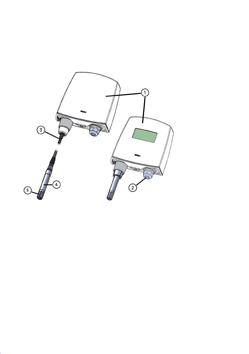
The following figure illustrates the main features of the HMT140. On the left is a remote probe
model without display, and on the right is a fixed probe model with the optional display. The
numbers and arrows indicate the main components of the HMT140 models.
Figure 1 HMT140 Features
HMT140 enclosure
1
2 Cable bushing: cable gland
3 Probe cable
4 HMP110 probe
5 Plastic grid filter
2.2.1 Installation Kit
The HMT140 is typically installed mounted on the wall with up to four screws (not included).
For duct mounting, Duct Installation Kits are available as accessories.
To help you position the screws correctly, use the Drilling Template, available inside the back
cover of the HMT140 Quick Guide.
12
Page 15

Chapter 2 – Product Overview
More Information
‣
Options and Accessories (page 10)
‣
Wall Mounting (page 20)
2.2.2 HMT140 Utility and Configuration Cable
To connect an HMT140 to your network, install the HMT140 Utility software and connect the
HMT140 to your PC with the HMT140 Configuration Cable (software and cable shipped with
viewLinc).
More Information
‣
Configuring the HMT140 to Your Network (page 26)
13
Page 16

1
2
3
3
4
5
6
7
9
8
HMT140 User Guide M211488EN-H
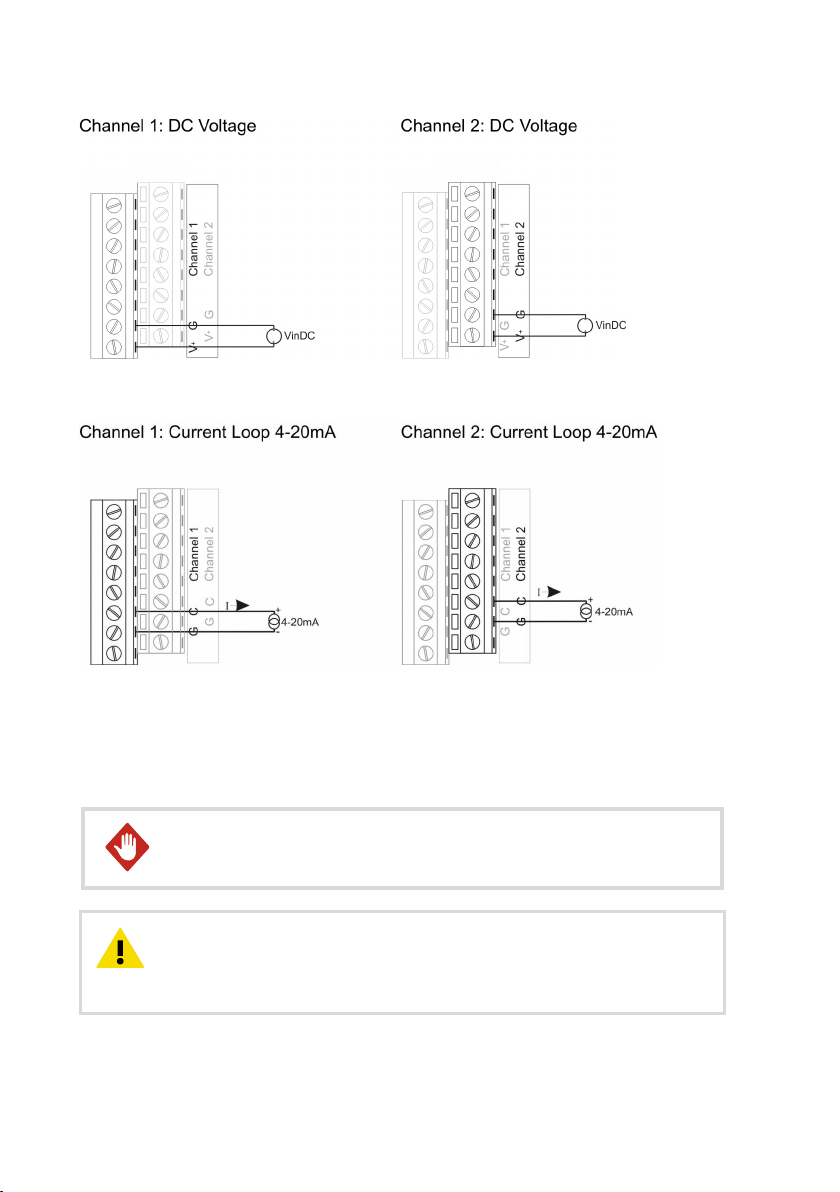
2.2.3 Connections and Wiring
Figure 2 HMT140 Components Diagram
CONFIG header
1
2 SERVICE button
3 Infrared sensor
4 Status LED
5 LCD
6 Power switch for battery
7 Cable grommet (rubber plug)
8 Cable gland
9 Channel wire terminals
14
Page 17
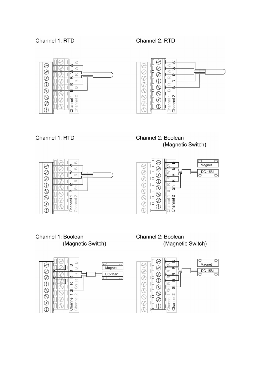
Figure 3 RTD Wiring Diagram
Chapter 2 – Product Overview
Figure 4 RTD and Boolean Wiring Diagram
Figure 5 Boolean Wiring Diagram
15
Page 18
HMT140 User Guide M211488EN-H
Figure 6 Voltage Wiring Diagram
Figure 7 Current Wiring Diagram
2.3
Safety
This product has been tested for safety. Note the following precautions:
Remove batteries before shipping.WARNING!
CAUTION!
documentation. Improper modification may lead to safety hazards, equipment
damage, failure to perform according to specification, or decreased equipment
lifetime.
16
Do not modify the unit or use it in ways not described in the
Page 19
Chapter 2 – Product Overview
WARNING!
protection provided by the equipment may be impaired.
CAUTION!
distance must be maintained between the user and the device when the device
is operating.
CAUTION!
20 cm. Cette distance doit être maintenue entre l'utilisateur et l'appareil lorsque
l'appareil est en fonctionnement.
If the equipment is used in a manner not specified by Vaisala, the
This device requires a separation distance of at least 20 cm. This
Cet appareil nécessite une distance de séparation d'au moins
2.3.1 ESD Protection
Electrostatic Discharge (ESD) can damage electronic circuits. Vaisala products are adequately
protected against ESD for their intended use. However, it is possible to damage the product by
delivering electrostatic discharges when touching, removing, or inserting any objects in the
equipment housing.
Avoid touching component contacts or connectors when working with the device.
2.4
Regulatory Compliances
This product complies with the following standards:
• EN 61326-1, EN 301 489-1
• EN 300 328 V2.1.1
This product complies with the following safety standard:
• EN 61010-1
In accordance with the provisions on the Radio Regulations of the People's Republic of China,
this radio transmission equipment, after examination, conforms to the provisions with its SRRC
ID:
• 2019DJ5109
This product contains a radio module with the following module approvals:
• FCC ID: U3O-G2M5477
• IC ID: 8169A-G2M5477
• NCC ID: CCAF11LP0240T6
1)
1) EN 61326-1 and EN 301 489-1 apply only to the EU and China specific versions of HMT140 loggers
with CE marking.
17
Page 20
R
201-12576
5
HMT140 User Guide M211488EN-H
•
当該機器には電波法に基づく、技術基準適合証明等を受けた特定無線設備を装着している
2.4.1 FCC Compliance Statement
This equipment has been tested and found to comply with the limits for a Class B digital
device, pursuant to Part 15 of the FCC rules. These limits are designed to provide reasonable
protection against harmful interference in a residential installation. This equipment generates,
uses and can radiate radio frequency energy and, if not installed and used in accordance with
the instructions, may cause harmful interference to radio communications. However, there is
no guarantee that the interference will not occur in a particular installation. If this equipment
does cause harmful interference to radio or television reception, which can be determined by
turning the equipment o and on, the user is encouraged to try to correct the interference by
one or more of the following measures:
• Reorient or relocate the receiving antenna.
• Increase the separation between the equipment and receiver.
• Connect the equipment into an outlet on a circuit dierent from that of the receiver.
• Consult the dealer or an experienced radio/TV technician for help.
WARNING!
subject to the following two conditions: (1) This device may not cause harmful
interference, and (2) this device must accept any interference received,
including interference that may cause undesired operation.
WARNING!
approved by the party responsible for compliance could void the user’s
authority to operate the equipment.
This device complies with part 15 of the FCC Rules. Operation is
Changes or modifications to this equipment not expressly
2.4.2 ISED Compliance Statement
This device complies with Industry Canada licence-exempt RSS standard(s). Operation is
subject to the following two conditions:
1. This device may not cause interference; and
2. This device must accept any interference, including interference that may cause undesired
operation of the device.
This device has a whip antenna with a gain of 2 dBi.
Le présent appareil est conforme aux CNR d’lndustrie Canada applicables aux appareils radio
exempts de licence. L’exploitation est autorisée aux deux conditions suivantes:
1. l’appareil ne doit pas produire de brouillage, et
2. l’utilisateur de l’appareil doit accepter tout brouillage radioélectrique subi, même si le
brouillage est susceptible d’en compromettre le fonctionnement.
Le présent appareil dispose d'une antenne fouet avec un gain de 2 dBi.
18
Page 21
Chapter 3 – Installation
3. Installation
3.1 Mounting
Depending on your installation requirements, you may wish to complete the network
configuration and setup prior to mounting. Note that you can complete the configuration and
setup procedures after mounting with a portable PC.
To connect the HMT140 to your network and view HMT140 data using viewLinc,
you require HMT140 Utility software and an HMT140 Configuration Cable (shipped
with viewLinc).
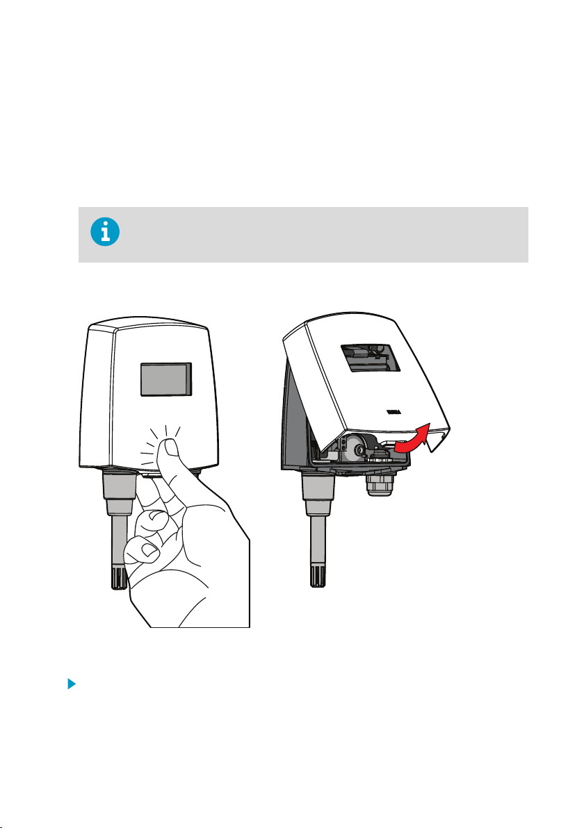
3.1.1 Opening Data Logger Cover
Figure 8 Opening Data Logger Cover
1. If the device is not mounted already, hold it against a flat surface.
2. Push on the cover with your thumb, and pull the bottom part of the cover towards
yourself.
19
Page 22

HMT140 User Guide M211488EN-H
3.1.2 Wall Mounting
Before mounting an HMT140 device, consider the environment. It is recommended that
wireless devices be mounted in an area with a minimum of wireless interference.
• If you plan to install a device without an LCD in a dark or low-light area, a high-trac area,
or an area with a solid object situated within 10 cm (3.9 in) of the front of the device, you
may want to turn o the proximity sensor to avoid triggering unnecessary transmissions
(see Modify Transmission Settings (page 28)).
• To ensure consistent communications and data transfer to Vaisala viewLinc, limit
interference from solid structures or wireless/microwave radiation. For additional
guidance, please contact Vaisala.
If mounting against a metal surface, be sure to keep a minimum of 2 mm (0.08 in)
between the metal and the back of the HMT140 to ensure an uninterrupted radio
signal.
1. Open the HMT140 cover.
2. Make sure that the HMT140 is correctly aligned and attach it directly to the wall with up to
four screws (not included in the package).
Select the size and type of the fastening screws according to the wall material (for
example, wood or stone). The diameter of the fastening screws is typically between 3.5
and 4 mm (0.14 and 0.16 in). Refer to the Drilling Template in the HMT140 Quick Guide.
20
Page 23

92 [3.62]
91 [3.58]
78 [3.07]
[in]
mm
Chapter 3 – Installation
Figure 9 Mounting Diagram
Vaisala strongly recommends you to use all four screws; however, the HMT140
enclosure fastening holes are initially covered with a thin plastic membrane, so
less than four screws could also be used without sacrificing the ingress protection
(IP) class of the enclosure.
21
Page 24

Ø 24 [0.94]
1
2
1 2 3
HMT140 User Guide M211488EN-H
3.1.3 Duct Installation
The duct installation kit includes a plastic pipe with a flange (Vaisala order code: 215619). To
install the HMP110 probe with the duct installation kit, drill a hole into the duct wall, assemble
the probe to the duct installation kit, slide the probe head through the hole, and attach the
flange to the duct wall with four screws.
Figure 10 Probe Installation with Duct Installation Kit
Tension screw
1
2 Installation depth. Adjust the depth and lock in place with the tension screw.
3.1.4 Probe Assembly with Duct Installation Kit
1. Pass the probe cable through the plastic pipe of the duct installation kit.
22
1 Probe (HMP110)
2 Duct installation kit
3 Probe cable
Page 25

42
1
2
3
Ø24
Ø3.2
29
[1.1]
59 [2.3]
20
[0.79]
Ø 15 [0.59]
205 [8.1]
42 [1.7]
53 [2.1]
Ø 22
[0.87]
6
[0.24]
Ø12
[0.47]
266 [10]
mm
[in]
42 [1.7]
42 [1.7]
Chapter 3 – Installation
2. Connect the probe cable to the HMP110.
1 Mounting screw
2 Tension screw
3 HMP110 assembled in duct installation
kit plastic pipe
To attach the probe assembly to the duct:
1. Drill the holes for the duct installation kit as follows:
• Use a 24-mm (0.9-in) drill bit to drill a hole in the wall.
• Use a 3.2-mm (0.1-in) drill bit to make 4 holes for the installation screws (four
ST4.2×16-C-Z DIN 7981 screws). The holes should be arranged in a square around the
24-mm (0.9-in) hole, at a distance of 42 mm (2 in) from each other.
2. Mount the probe holder using the screws.
3. Adjust the depth of the plastic pipe and tighten the screw to lock the probe in place.
Figure 11 Dimensions of HMP110 Probe with Duct Installation Kit
23
Page 26

HMT140 User Guide M211488EN-H
3.2 Optional Mounting Accessories
3.2.1 Probe Mounting Flange
The probe mounting flange (Vaisala order code: 226061) is a general purpose mounting flange
for 12 mm (0.5 in) diameter probes. It can be used to hold the HMP110 probe in a through-wall
installation.
The silicone plug that is delivered with the flange is not suitable for use with the
probe cable of the HMT140.
Figure 12 Optional Probe Mounting Flange
3.2.2 Probe Mounting Clamp
The optional mounting clamp (Vaisala order code: 226067) makes it easy to install the probe
on the wall of the measurement environment. The probe can be detached for calibration
simply by loosening the lower screw.
Installing the entire probe in the measurement environment prevents heat conduction to the
sensor, and is the recommended installation method.
Figure 13 Optional Probe Mounting Clamp
24
Page 27

Chapter 4 – Set Up and Operation
4. Set Up and Operation
4.1 Connect and Configure
The HMT140 Configuration Cable allows you to connect an HMT140 to your PC. You can then
configure the HMT140 with your network settings using the HMT140 Utility software (software
and cable shipped with viewLinc).
4.1.1 Installing HMT140 Utility Software
The HMT140 Utility software configures and reads the settings in the HMT140 that use 802.11b
and 802.11g wireless networks. The address of the destination host, the wireless network
parameters, transmit period, and other important network functions of the HMT140 are
specified using the HMT140 Utility. The HMT140 Utility also provides you with access to tools
for diagnosing connection problems.
Before you configure the HMT140, install the HMT140 Utility software on a PC. The HMT140
Utility is compatible with Windows 10 (64-bit), Windows 8.1 (64-bit), Windows 7 (32-bit and
64-bit), Windows XP (32-bit), Windows Server 2008, and Windows Server 2012.
To install the HMT140 Utility software:
1. Disconnect the HMT140 Configuration Cable if it is already connected to your PC.
2. Insert the CD that came with the HMT140 Configuration Cable, or download the software
from www.vaisala.com/hmt140.
3. Run the HMT140 Utility installation program (HMT140UtilitySetup.exe).
4. Accept the license agreement terms, then click Next to accept the installation default
settings. The installation of the driver may take several minutes.
5. After the software is installed, connect the HMT140 Configuration Cable to a USB port on
your PC to complete the installation setup.
6. When the installation is complete, disconnect the cable from your PC. You are now ready
to set up and configure your device.
If you wish to remove the Vaisala HMT140 Utility software at a later date, use the uninstall
function in the Windows Control Panel.
4.1.2 Setting up HMT140 Hardware
Once the HMT140 Utility software is successfully installed, you can set up your data monitoring
device.
To set up the HMT140 for the first time:
1. Make sure the HMT140 Configuration Cable is disconnected from your PC.
2. Open the HMT140 cover.
3. Make sure the power switch on the device is in the OFF position.
25
Page 28

HMT140 User Guide M211488EN-H
4. Install three 3.6V lithium batteries. For the recommended battery type, see Options and
Accessories (page 10).
5. Turn the power switch on the device to the ON position, and wait for the setup process to
complete (five seconds). LED light turns on, then o.
4.1.3 Configuring the HMT140 to Your Network
After you install the HMT140 Utility and set up the HMT140, use the Configuration Cable and
HMT140 Utility software to connect and configure the HMT140 to your network.
To avoid depleting the battery power too quickly, make sure that your network is
on-line and available before configuring your device.
The following steps provide you with standard network settings. To set specific settings
depending on your network configuration, see Custom Settings (page 28).
Follow the steps carefully. Do not connect the Configuration Cable to the HMT140
configuration port unless the Configuration Cable is connected to a computer
USB port, the batteries are installed, and the power switch is in the ON position.
To configure the HMT140 for your network with standard settings:
1. Make sure that the HMT140 cover is open and the correct batteries are installed.
2. Turn on the HMT140 and wait five seconds to make sure the startup process completes.
3. Plug the USB connector on the HMT140 Configuration Cable to the computer, if it is not
already connected.
4. From the Start menu, open the HMT140 Utility.
5. Connect the end of the HMT140 Configuration Cable labeled USB Wi-Fi Programmer to
the 4-pin HMT140 CONFIG header.
6. On the HMT140 Utility Setup tab, click Retrieve to identify the HMT140.
The bottom left status bar will initially read Looking for sensor or USB programmer, then,
once the HMT140 is identified, the status bar will read Found USB Programmer.
26
Page 29

Chapter 4 – Set Up and Operation
7. Click Retrieve again to force retrieval of current settings. The connected type is identified
in the upper right corner of the Setup tab window.
The status bar is located at the bottom of the HMT140 Utility window. It contains the
following panels:
• Left panel: Displays the Configuration Cable status: Found USB Programmer or
Looking for USB Programmer.
• Middle panel: Displays progress messages of the dierent actions: Update, Retrieve,
Status, and Info.
• Right panel: Displays a message when the parameters on the Setup page have been
modified and require saving.
8. If the IP address is static, uncheck the IP Address Dynamically Assigned option and enter
the network parameters. Otherwise leave this option checked.
For additional IP address settings information see, Check Transmission Status (page 31).
27
Page 30

HMT140 User Guide M211488EN-H
9. Enter the parameters for the WLAN (wireless LAN router settings).
10. Enter the Destination IP address/name and port number of the host (viewLinc server
settings).
If you do not know the information required, request these parameters from
your network administrator.
11. Click the Sensor tab and select a Transmit Period Time and number of Tries, or accept
the default settings.
12. Click Update. The HMT140 Utility will configure the HMT140.
13. Select the Status tab to check that the settings appear as configured. Click Get if the
settings do not appear automatically.
14. Disconnect the HMT140 Configuration Cable from the HMT140 and wait for eight seconds.
15. Press the SERVICE button on the HMT140.
Optional: Enter a name for the saved settings on the Setup tab in the Saved Settings field,
and click the disk icon to save.
To configure custom settings for the HMT140, see Custom Settings (page 28).
4.1.4 Setup Consideration
If DHCP or DNS is being used, it is best to use local DHCP and DNS servers rather than a DNS
server on the internet. The local servers will give better response times compared to the
remote servers and, as a result, help to conserve battery life.
4.2
Custom Settings
Use the HMT140 Utility to make additional changes to the network configuration settings of an
HMT140 data logger.
4.2.1 Modify Transmission Settings
Before making changes to transmission settings, consider the impact to battery life.
1. Make sure the HMT140 cover is open and the correct batteries are installed.
2. Turn on the HMT140 and wait five seconds to make sure the startup process completes.
3. Plug the USB connector on the HMT140 Configuration Cable to the computer, if it is not
already connected.
4. From the Start menu, open the HMT140 Utility.
5. Connect the end of the HMT140 Configuration Cable labelled USB Wi- Fi Programmer, to
the 4-pin HMT140 CONFIG header.
6. On the HMT140 Utility Setup tab, click Retrieve to identify the HMT140 and view current
settings.
28
Page 31

Chapter 4 – Set Up and Operation
7. On the Sensor tab, select from the following options:
• Transmit Period: Select how frequently the HMT140 transmits data. In the event of an
alarm condition, transmission frequency is overridden automatically. If you require a
faster transmit period, the HMT140 Utility version 1.1.4.0 and higher provide additional
options. Select the Options menu and then Advanced. Check the option Extended
Transmit.
• Tries: Select the number of transmission attempts permitted for the specified
Transmit Period.
CAUTION!
Increasing the transmission frequency will deplete
batteries more rapidly.
29
Page 32

HMT140 User Guide M211488EN-H
For example, if you select 15 minutes for the Transmit Period, and 3 for the number of
Tries, the HMT140 will attempt to transmit every 15 minutes. If the transmission does
not complete successfully, it will make two additional transmission attempts, then will
go into ‘sleep’ mode until the next scheduled transmit period.
• Logging Period: Specify how often the HMT140 will log I/O into the log buer. If you
are using HMT140 Utility version 1.1.4.0 or higher and require a more frequent log
period, select the Options menu then Advanced, and check the option, Log Periods.
• Enable Beeper/Enable Push Button Control of Beeper: Select the option to enable or
disable the button control of the Beeper (whether you want to be able to turn the
Beeper on or o with the push button on the HMT140). It is also possible to turn the
Beeper on and o by holding down the SERVICE button for approximately five
seconds. The Beeper is enabled by default. There is no external Beeper status
indicator. It must be enabled/disabled with the SERVICE button.
• Enable Proximity Attention Sensor: Select this option to enable or disable the
proximity attention sensor. The sensor is used to wake up the HMT140, turn on the
display (if present), and to force the HMT140 to send a data packet to the host. If your
HMT140 does not have an LCD or is installed in an area where the IR sensor may be
triggered more frequently (due to low-light, high-trac or transmission obstacles),
turn o the sensor to save battery life.
• Display On Time: Select the length of time the display stays on (choose a minimum
length of time to save battery power).
• HMP110 Polltime: If your HMT140 uses an HMP110 Probe, select how frequently the
HMT140 polls the HMP110 probe (leave at the default setting, two minutes, to save
battery power).
The polling rate should be equal to or faster than the Logging Period,
otherwise you will record the same measurement multiple times.
• Low Battery Alert: Specify at what percentage of battery power remaining you want
the Low Battery indicator to display and notify the host software.
• Stop Xmit at Battery Remaining: Specify at what percentage of battery power
remaining you want the HMT140 to stop transmitting data to the host (to save battery
power). Once this threshold is reached, the HMT140 continues to log data and
function normally, but it will not transmit data using the Wi-Fi radio.
8. Use the Display Contrast interactive control to set the HMT140 display contrast. When the
Up, Down or Set buttons are clicked, the HMT140 Utility will attempt to set the contrast.
The contrast value can only be set when you click Set. The value is not set
with the Update or Retrieve buttons.
9. Click Update. The HMT140 Utility will send these settings to the HMT140 and then reboot.
After the settings are successfully configured, a dialog displays Configured!. If there was
an error sending the settings, the HMT140 Utility will display the error in a popup dialog
window. The center panel in the bottom status bar will display the update status.
30
Page 33

Chapter 4 – Set Up and Operation
10. Select the Status tab to check that the settings appear as configured. Click Get if they do
not appear automatically.
11. Disconnect the HMT140 Configuration Cable from the HMT140 and wait eight seconds.
12. Press the SERVICE button on the HMT140.
Optional: Enter a name for the saved settings on the Set up tab in the Saved Settings
field and click the disk icon to save. If the HMT140 is used with more than one wireless
network, enter a name in the Saved Network Settings field and click Save. Other network
settings files can be saved and recalled from the Saved Settings field.
More Information
‣
Options and Accessories (page 10)
‣
Battery Usage (page 36)
‣
Viewing Battery Life Remaining (page 36)
4.2.2 Modify HMT140 Description
If you want to make it easier to identify specific HMT140 data loggers, enter custom names. By
default, each HMT140 is identified using the model name and channel type.
Check with your network administrator before making changes.
To modify your HMT140 name and channel descriptions:
1. Complete steps 1 to 6 in Modify Transmission Settings (page 28).
2. Select the Description tab and enter a name, and/or Channel descriptions. You can view
these descriptions in viewLinc, and make changes in viewLinc if required.
4.2.3 Check Transmission Status
The Status page displays the current state of the IP settings, connection status, signal
strength, and battery life parameters, as applied using the Update button on the Network tab.
To monitor the transmission status:
31
Page 34

HMT140 User Guide M211488EN-H
1. On the Status tab, click Get to update the HMT140 Utility window with the latest status
information: IP settings, WLAN and Sensor battery. If successful, the HMT140 Utility
displays the information on the Status page.
32
Page 35

Chapter 4 – Set Up and Operation
2. Read IP Settings status.
• DHCP:
• O – static IP address information is being used
• On – IP settings are successfully assigned
• Cache – IP settings are successfully assigned and the HMT140 will cache this IP
address
• Failed – the HMT140 could not obtain the IP settings.
• IP Address: Current IP address. If “0.0.0.0”, then no IP address has been assigned.
• Subnet Mask: Current assigned subnet mask.
• Gateway: Current assigned gateway address.
• DNS: Current assigned Name Server address.
• Resolved Destination: Appears if the hostname is given for the Destination.
3. Read WLAN status.
• Connection:
• Failed: The HMT140 has failed to connect to a wireless network.
• Associated - Not Connected: The HMT140 has associated with the network but
has not connected.
• Authenticated - Not Connected: Security settings have been authenticated but
has not connected.
• Assoc/Authen - Connected: The HMT140 has associated and authenticated to the
network and connected successfully to the network.
• Signal Strength: Signal strength of the last communications. The signal strength can
vary from reading to reading. Multiple samples should be taken to determine the
signal strength.
• Channel: This is the channel found during the Channel Auto Find feature or the
channel set in the Setup page. If the HMT140 cannot find a channel when in Auto Find
mode, the utility will display “none”.
4. Check HMT140 battery status.
• Est. Life: Estimated percentage remaining of the battery.
• Est. Expired: Estimated date when the battery should be changed (dependent on the
Transmit Period and the number of alarms).
More Information
‣
Battery Usage (page 36)
‣
Viewing Battery Life Remaining (page 36)
4.3
HMT140 Function Modes
4.3.1 Operating Modes
The HMT140 operates in two modes: Config mode and Transmitter mode.
33
Page 36

HMT140 User Guide M211488EN-H
Config Mode
When the HMT140 is powered on, and the HMT140 Configuration Cable is connected to it, the
HMT140 connects to the network for about two seconds and then goes to sleep. When new
activity occurs, the HMT140 will wake again, connect, then go back to sleep after five seconds.
Transmitter Mode
When the HMT140 is powered on and the HMT140 Configuration Cable is not plugged into it,
data is transmitted according to the transmit settings.
In Transmitter mode, the HMT140 spends most of its time in a very low power state (sleep) to
save battery power. When a transmit period is due, it powers up the radio, attempts to link to
the specified wireless network, transmits its data and then goes back to sleep. The HMT140
transmits based on the configured transmit period or when it is entering an alarm state.
4.3.2 Transmission of Data
The HMT140 will go through the following steps in order to connect to a network and deliver
data:
1. Associates with the network.
2. HMT140 authenticated by the network (depends on the type of security).
3. Requests IP from DHCP Server (if set to dynamic IP)
4. HMT140 receives request from Name Server IP address of hostname (if a hostname is
used for the Destination address and DNS Server specified).
5. Sends data.
6. viewLinc returns acknowledgement.
4.3.3 Transmit Attempts
The HMT140 will initiate a Transmit Attempt repeatedly (typically every 30 seconds) until
either an acknowledgement is received from the host, or the number of tries has been
exhausted. It follows this transmission mechanism both when the transmit period arrives and
for alarm attempts.
CAUTION!
it to join. Without a valid network to join, the device will wait for the maximum
allowable period for a response (Transmit Period multiplied by Tries), thereby
rapidly draining its batteries.
The HMT140 should not be turned on until a network is available for
4.3.4 Alarm-Triggered Transmission
The HMT140 has the ability to initiate a Transmit Attempt based on an alarm, if this
functionality is configured in viewLinc.
34
Page 37

Chapter 4 – Set Up and Operation
An alarm can be triggered either when the measured value exceeds a high threshold or goes
below a low threshold for a period of time, as configured in viewLinc as HighHigh or LowLow
threshold alarm settings. The HMT140 can also be configured to initiate a Transmit Attempt
when it exits an alarm state. Refer to the Vaisala viewLinc User Guide for information about
alarm settings.
4.4 Additional Settings
4.4.1 Change Input/Output Scale
If you want your HMT140 to provide more meaningful voltage or current output
measurements, you can modify the output settings (if you are not sure if your network
requires or supports this option, contact Vaisala Technical Support for assistance).
To modify voltage or current input/output values:
1. From the Setup tab, select the I/O Definition tab.
2. Enter the input range values of the HMT140.
35
Page 38

HMT140 User Guide M211488EN-H
3. Enter required Display Units, the number of decimal places you want recorded, the
high/low output values and desired measurement units.
4.4.2 Save and Recall Settings
Your setup parameters can be saved and associated with a name on the Setup tab, in the
Saved Settings field. These setup parameters can then be recalled by that name, saving you
time reentering the settings.
The network parameters can also be saved separately and associated with a name on the
Network tab, in the Saved Network Settings field. The network setup parameters can then be
recalled by that name.
4.4.3 Delete Saved Settings
Both the Saved Settings and the Saved Network Settings can be deleted, to help keep the list
of saved settings easier to view and/or manage.
1. On the File menu, select Delete Sensor Setup or Delete Network Setup, then choose the
correct settings name to delete.
4.4.4 Restart the HMT140
You may want to reboot your HMT140 to reconnect to the network and re-acquire status
information.
1. On the Status tab, click Restart.
4.4.5 Get General Information
To gather general information about the HMT140, select the Info tab and then click Get. The
HMT140 Utility will retrieve the following information:
• MAC address
• Firmware version
• HMT140 serial number
• HMP110 serial number (if using)
4.5
Battery Usage
The HMT140 has a built-in battery meter. The meter provides a general estimate of battery
power remaining by calculating the number of transmission attempts relative to the number of
transmissions expected from the battery.
4.5.1 Viewing Battery Life Remaining
The HMT140 Utility displays the estimated battery expiration and the estimated battery life
percentages on the Status page.
36
Page 39

Chapter 4 – Set Up and Operation
To improve battery life, consider increasing the amount of time between transmit periods.
Transmit Period (Minutes) Estimated Battery Life (Months)
15 18
10 12
5 6
2 2.4
To view battery life remaining, view the battery meter status in the Est. Life field in the Status
tab.
To reset the battery meter:
The meter must be reset after installing new batteries to ensure the battery meter
status estimate is accurate.
o the HMT140. Make sure the Configuration Cable is disconnected.
1. Turn
2. After replacing batteries, press and hold the SERVICE button.
• Turn the HMT140 power switch on while the SERVICE button is engaged.
• Wait approximately 10 seconds until the LED light flashes and you hear several beeps.
3. Release the SERVICE button to complete the battery meter reset.
4. Confirm that the battery meter is reset:
• Reconnect the Configuration Cable to the HMT140 and your PC.
• Start the HMT140 Utility.
• On the Setup tab click Retrieve.
• On the Status tab the Est. Life field should indicate 100 %.
More Information
‣
Battery Replacement (page 48)
4.5.2 Units and Temperature
Use the Options menu to set the measurement units you want to display on screen.
To change display units:
1. On the Options tab, select Units.
37
Page 40

HMT140 User Guide M211488EN-H
4.5.3 Connection Performance
Consistent connection performance is essential for longevity of battery life. The HMT140 Utility
can perform a test to indicate how well the HMT140 connects to the network, which provides
an indication about the expected battery life.
If the average connection time is more than five seconds, the HMT140 may not
connect consistently and the battery may be exhausted before the battery meter
indicates.
More Information
‣
Test Network Connectivity (page 43)
4.5.3.1 Connect Times
The following are the components of the connect time:
Table 3 Connect Time Components
Description Option 802.11b (sec) 802.11g (sec)
HMT140 Startup No 2 0.1
Auto Find Channel Yes 1 0.1
Associate/Authentication No < 1 < 1
DHCP lookup Yes < 1 < 1
DNS lookup Yes < 1 < 1
Cache/Noncache
4.5.3.2 Determining Connection Problems
In some networks, one of the optional components of the connect time may take too long to
perform on a consistent basis. If the average connection time is too long it is important to try
isolate the cause.
To isolate a connection problem:
1. Open the HMT140 Utility and connect the Configuration Cable to the HMT140 and your
PC.
2. Temporarily turn o one of the connection options and then measure the average
connection time:
• Try setting the dynamically assigned IP address as the static address temporarily, or,
• Try using a Destination IP address instead of the hostname address temporarily.
38
Page 41

Chapter 4 – Set Up and Operation
3. Select the Tools tab. In the Test Connect Time area, click Start. The HMT140 Utility will
repeatedly attempt to connect to the network with one second between connection
attempts. You can then view:
• Number of connection attempts.
• Last connect time.
• Average, minimum and maximum connect times.
• History of connect attempts displayed as a bar graph (each bar graph is the number
of seconds for the attempt).
• Failed connection attempts displayed as a grey bar. Failed connection attempts are
not factored in the statistics.
4. To change the Connect Window time, on the Options menu select Advanced Options,
and then select the desired Connect Window time.
4.6 Advanced Options
These advanced parameters (Options > Advanced Options) are applied each time an Update
function is performed (available in HMT140 Utility version 1.1.4.0 and higher).
CAUTION!
transmission performance and reduce battery life.
• Extended Transmit, Log Periods and HMP Polltime: Adds an additional transmission,
logging and polling time periods on the Sensor tab. These additional periods are meant to
be used for testing, evaluation and demonstration of the HMT140 and, if used regularly,
can have a severe impact on battery life.
• Log Conversations: When this option is selected, the HMT140 Utility will capture the
conversation between the utility and the HMT140 and place it in a file called
OutputLog.txt. To locate the file, go to the Help menu, select Utility Folder Paths, and
then Explore Data.
• DHCP Caching: When this option is selected, the HMT140 will cache its IP address
assigned from the DHCP server until the DHCP lease time has expired or the HMT140 is
power-cycled. If not selected, the HMT140 will request an IP address each time it attempts
to contact the host.
• ARP Caching: When this option is selected, the HMT140 will store and keep a list of
IP/MAC relationships. If not selected, the HMT140 will rebuild the IP/MAC relationships
with every attempt to contact the host.
• DNS Caching: When this option is selected, the HMT140 will cache the IP address that
results from the DNS lookup of the Destination hostname. The HMT140 will keep the
destination IP address until either the DHCP lease time expires or the HMT140 is powercycled. If not selected, the HMT140 will request a DNS lookup of the Destination hostname
each time it attempts to contact the host. This setting is not recommended for most
monitoring systems.
• Allow Channels 12 and 13: Enable the use of channels 12 and 13. This option should only
be used in regions in where these channels are not restricted.
Modification of these parameters may negatively impact
39
Page 42

HMT140 User Guide M211488EN-H
• Connect Window: Set the amount of time in seconds (three to eight seconds) that the
HMT140 will attempt to associate and authenticate to an access point or a wireless router
(this includes the time to obtain an IP address from a DHCP server). The default rate is five
seconds.
• Data Rate: The default data rate is 1 Mbit/sec. and can be set from one to 54 Mbit/sec. The
lower the data rate the longer range the HMT140 will have. The 802.11b data rates are: 1, 2,
5.5 and 11. All other data rates are 802.11g data rates. An access point or wireless router
may be configured to exclude 802.11b data rates.
• Override Destination Port: Leave blank to not use this feature. If a number (1 to 65535) is
placed in this field, the Utility will force the Destination Port to use this entered number.
Use this feature to force the Destination Port to another value other than the default 6767.
4.6.1 Passwords
To improve security, you can require that a user log in to make changes to HMT140 parameters.
If Passwords are enabled, a password prompt appears when a user clicks Update on the Setup
tab. No other HMT140 functions will require a login password.
CAUTION!
Vaisala viewLinc software. Passwords may limit the ability of viewLinc to update
settings or values in the device. For example, changes to a threshold alarm
template in viewLinc may not transfer to the HMT140 if passwords are required
on the device.
To set, change or remove an HMT140 password:
1. Open the HMT140 Utility.
2. Connect the HMT140 to your computer.
3. From the Options menu, select Advanced Options.
4. On the Advanced Options window, check Enable use of passwords in HMT140, then click
OK.
5. To set the password for the first time:
• Leave the Current Password field blank.
• Check the Change Password option.
• Enter the new password in the New Password and New Password Again fields.
• Click Update.
6. To change an existing password:
• Enter the current password.
• Check the Change Password option.
• Enter the new password in the New Password and New Password Again fields.
• Click Update.
7. To clear a password:
• Enter the current password.
• Check the Change Password option, and leave the New Password and New
Password Again fields blank.
• Click Update.
Use of passwords in the HMT140 is not recommended for use with
40
Page 43

Chapter 4 – Set Up and Operation
CAUTION!
HMT140 does not save the password. If the password is forgotten, contact
Vaisala Technical Support.
Record the password in a safe location for safe-keeping; the
4.6.2 Set Up a New Channel
On the Network tab, you can select a specific channel to view, using the Channel field.
To select multiple channels for the HMT140 to search when connecting to an access point or a
wireless router, select Auto Find.
The Channel Auto Find feature defaults to search for channels 1 through 11. These
channels are set in the .INI file of HMT140 Utility.
For Wi-Fi 802.11b radio mode, do not set the Channel Auto Find search channels to more than
3 channels. This will have an eect on the range and battery life of the HMT140.
For Wi-Fi 802.11g radio mode, the HMT140 can search all channels with minimal eect on
battery life and range.
More Information
‣
Additional Program Parameters (page 43)
4.6.3 Find Additional Networks
To locate additional networks:
41
Page 44

HMT140 User Guide M211488EN-H
1. On the Setup tab, on the Network page, click the Find Networks button to scan for all
available wireless networks. The HMT140 Utility displays details about the currently
available networks: SSID: SSID of the access point or router (wireless channel).
• MAC: MAC address of the access point or router.
• Channel: Channel of the access point or router.
• Security: Security setting of the access point or router. Note that some security
settings will not work with the HMT140.
• RSSI: Current signal strength.
2. To select a network, click on the row in the Available Networks window, then click OK.
The HMT140 Utility automatically places the network settings information in the
appropriate fields in the Setup tab.
During the Find Networks operation, the HMT140 is disconnected from the
current network. To reconnect, either click Update on the Setup tab or click
Restart on the Status tab.
42
Page 45

Chapter 4 – Set Up and Operation
4.6.4 Test Network Connectivity
Ping from Sensor
For radio module version 2.27 and earlier (Utility > Info tab): When the Ping From Sensor
button is clicked, the HMT140 will use either the IP address in the IP Address field or the
current address in the Destination IP field in the Setup tab and ping that specified address.
Once the ping operation is complete, the utility will either indicated failed or success and
specify the IP address in the Result field.
Ping from This PC
When the Ping From This PC button is clicked, the HMT140 will use either the IP address in the
IP Address field or the current address in the Destination IP field in the Setup tab and ping that
specified address from the local PC. Once the ping operation is complete, the utility will either
indicated failed or success and specify the IP address in the Result field.
Contact Destination Host
The HMT140 Utility will instruct the HMT140 to send a transmission (data packet) to the
Destination Address. If the Destination responds with an acknowledgement, the Utility will
indicate success, otherwise the Utility will display "Failed" in the Result field. Use the Contact
Destination Host function to confirm that the HMT140 is sending packets to the Destination.
The Destination must be capable of responding with an acknowledgement for this
function to work.
4.7 Additional Program Parameters
The HMT140 Utility stores all program information in an INI text file, HMT140Utility.INI.
You can use this file for reference, and, if you are updating several HMT140 loggers, save time
by making edits to the file directly.
To modify the HMT140Utility.INI file:
1. Go to the Help menu, select Utility Folder Paths, and then select Explore Setup.
2. Double-click the file, HMT140Utility.INI. It will open in a text editor.
3. To set the maximum number of tries (updates the Tries field, default maximum is 5):
[Settings]
MaxNumTries=5
43
Page 46

HMT140 User Guide M211488EN-H
4. To modify the default UDP port (default is 6767): code
[Settings]
DefaultPort=6767
5. To specify the auto find channels:
[Settings]
ChannelMask=1,2,3,4,5,6,7,8,9,10,11
6. Restart the HMT140 Utility to apply the changes.
44
Page 47

Chapter 5 – Maintenance
5. Maintenance
5.1 Improving Sensor Response Time
To ensure maximum operating life and a fast sensor response time, replace a dirty filter. The
filter should be replaced when it is damaged or dirty. Do not attempt to clean the filter.
To change the filter:
1. Turn the filter counter-clockwise to loosen it.
2. Remove the filter from the probe.
CAUTION!
filter in place, the sensors are easily damaged – handle the probe carefully.
3. Install a new filter on the probe, and tighten it so it is finger-tight.
4. Make sure the filter sits straight and meets the threads properly.
5.2
Removing and Fastening Probes
Be careful not to touch the sensors with the filter. Without the
5.2.1 Fixed Probe Model
To remove and replace a fixed probe:
1. Loosen the metal locking bushing by carefully turning it counter clockwise.
2. Remove the probe from the HMT140 by pulling it gently outwards.
3. Attach the new probe to the 4-pin M8 panel connector on the HMT140 (only one position
possible).
45
Page 48

HMT140 User Guide M211488EN-H
4. Tighten the locking bushing to the M8 panel connector by turning it clockwise.
Figure 14 Fixed Probe Model
Holder bushing (attached permanently to the probe)
1
2 HMP110 probe
3 Locking bushing
5.2.2 Remote Probe Model
To remove and replace a remote probe:
1. Unscrew the small sleeve at the end of the probe cable that secures the probe in place,
and pull out the probe.
46
Page 49

Chapter 5 – Maintenance
2. Replace the probe and screw the small sleeve back on, securing the probe tightly in place.
Figure 15 Remote Probe Model
1 Probe cable
2 Sleeve securing the probe to the cable
3 HMP110 probe
5.3 Calibration and Adjustment
HMP110 probe calibration status can be viewed with the HMT140 Utility. Calibration settings are
adjusted using viewLinc.
To view probe calibration status:
1. On the Info tab, click Get. This page will display calibration information including
calibration date, calibrator, and next calibration due date.
Please refer to the Vaisala viewLinc User Guide for further information, or visit
www.vaisala.com/viewlinc.
For calibration of HMP110 probes, refer to the supporting documentation available on the
Vaisala website.
47
Page 50

HMT140 User Guide M211488EN-H
5.4 Battery Replacement
When replacing batteries, it is important to use new, recommended batteries and to reset the
battery meter to make sure an accurate estimate of battery life remaining.
To replace the batteries and reset the battery meter of the HMT140:
1. Open the HMT140 cover.
2. Turn the power switch o.
3. Remove the batteries by pulling them up firmly. If the battery does not come out easily,
gently pull back on one of the battery holder tabs first.
4. Reset the battery meter:
• Press and hold the SERVICE button.
• Turn the power switch on.
• Wait approximately 10 seconds until the LED light flashes and you hear several beeps.
5. Release the SERVICE button.
6. Confirm that the battery meter is reset:
• Reconnect the Configuration Cable to the HMT140 and your PC.
• Start the HMT140 Utility.
• On the Setup tab, click Retrieve.
• On the Status tab, the Est. Life field should indicate 100 %
More Information
‣
Options and Accessories (page 10)
48
Page 51

Chapter 6 – Troubleshooting
6. Troubleshooting
Use HMT140 Utility to help troubleshoot issues that may occur while connecting the HMT140
to a wireless network.
6.1 HMT140 Operation Mode
When the Configuration Cable is connected to the HMT140, it enters Config mode. In this
mode, the HMT140 continuously attempts to connect to the wireless network and stays
connected until the Configuration Cable is disconnected or the setup has changed.
The HMT140 is in Transmitter mode when the Configuration Cable is not connected, and the
HMT140 power switch is turned on. When in Transmitter mode, the HMT140 remains in a low
power state, but will turn on, connect, transmit a UDP packet, and then go back to the low
power state when it is ready to transmit.
6.2
Signal Strength
The HMT140 works best with signal strengths above -63 dBm (for 802.11b mode) and -75 dBm
(for 802.11g mode). If the signal strength is less, the HMT140 may work marginally or not at all.
Stronger signal strength improves transmission performance.
Since the signal strength will vary from sample to sample, you should take multiple samples to
determine the signal strength. View signal strength on the Status tab and in the Available
Networks window (click the Find Networks button on the Setup tab).
6.3
Indicator Lights
The red LED on the main board (Center, or below LCD) indicates that a transmit attempt has
just started. The LED on the radio module indicates that radio module is connected to the
network. When in Transmitter mode the LED will flash when a connection is made. When in
Config mode (the programming cable is connected to the HMT140) the LED will remain on
continuously when a connection is established.
6.4
Access Points
Some access points have a mode called Auto Channel mode where it will move between up to
11 channels. If the access point is using this feature the HMT140 may work properly in Config
mode, but could fail or work very marginally in Transmitter mode. If the access point is using
Auto Channel mode, make sure the HMT140 has "Auto Find" for the channel and the right
channels have been selected for "Auto Find" channels.
Some access points will move between three channels (typically 1, 6, and 11). The HMT140
Utility will work with these access points with the Channel Auto Find feature but the channels
that are used must match the channels for which the HMT140 is configured.
49
Page 52

HMT140 User Guide M211488EN-H
6.5 Transmit Cycle
In Transmitter mode, it can take up to five seconds for the transmit cycle to complete. Transmit
time is calculated from when the SERVICE button is pressed to when the acknowledgement is
received from the host.
6.6 Frequently Asked Questions
Is the connect time too long?
If the connect time to the network is consistently long (over five seconds), the HMT140 may
not be able to connect to the network. If you suspect the connect time to the network is long:
1. Use the Test Connect Time tool (see Determining Connection Problems (page 38)), or,
2. Use a PC to connect to the network and then measure the time it takes to connect.
3. If the network consistently takes longer than five seconds to connect, you may need to
adjust the settings:
• Set the Connect Window to a longer value (use the Connect Time tool to help
determine this value) or,
• Change a connection component like channel Auto Find or DHCP.
Extending the connect time may decrease battery life.
Why can't I connect to the wireless network?
1. Verify that the network exists.
2. Verify signal strength. Use the built-in signal strength meter. Determine if adequate signal
strength exists at that location. See Signal Strength (page 49).
3. Verify your network settings.
4. Make sure the router or Access Point accepts connections of 1 Mbps. Some access points
may be set up to exclude certain WLAN data rates. You may have to change the WLAN
data rate setting in the HMT140.
5. If the HMT140 was previously connected at one location, but will not connect at the new
location, temporarily move it to the previous location and verify operation. It is also
possible that a setting on the network has changed.
I can connect to the network, but cannot obtain a dynamic IP
address
1. Verify your network settings.
2. Verify that you are connected to the right network.
3. Use the Ping from PC function in the HMT140 Utility to see if your PC can ping an address
on that network (your PC must be connected to that network).
50
Page 53

Chapter 6 – Troubleshooting
4. Use the Ping from PC function in the HMT140 Utility (if this PC is connected) and see if
you can ping the HMT140 when it is in Config mode. Go to the Status tab to determine the
IP address.
5. Use a static IP address temporarily and connect to the network to determine if HMT140
transmissions are being received by the host.
6. Make sure the DHCP Server has not exhausted the number of assignable IP addresses.
7. Check if the DHCP Server needs to be configured to accept this type of device (it is
possible the DHCP Server is taking too long to respond to the request).
I can connect to the network, but host is not receiving UDP
packets
1. Verify your network settings.
2. Verify that you are connected to the right network.
3. Verify that the Destination IP address is correct.
4. If using the broadcast address, verify that the network can support broadcasts. Most
routers by default will not route broadcast trac.
5. Use the Ping from PC feature if this PC is connected or a PC on the network and ping the
host. Also try pinging the HMT140 when it is in Config mode.
6. Check the following:
• Is the host is ready to receive the transmit packets?
• Is the host configured to listen for the UDP packets?
• Is the host software running?
• Is firewall software installed at the host that would prevent the UDP trac?
• Is there anything on the network that would restrict packets from being routed (like
MAC filtering)?
7. Perform a destination test (use the Contact Destination Host function from the Tools
tab).
8. If using a hostname for the destination address, make sure the DNS address is correct
(whether set as static or obtained through the DHCP server).
9. Check if the hostname is being resolved in Config mode (go to the HMT140 Utility Status
tab and examine the Resolved Destination field).
I can connect to the network and Contact Destination using the
utility, but host is not receiving UDP packets in Transmitter
mode
1. Verify your network settings.
2. Check if the access point using Auto Channel mode is switching between channels. The
access point may have switched to a dierent channel than is set up in the HMT140.
51
Page 54

HMT140 User Guide M211488EN-H
3. Use the Test Connect Time tool in the utility to verify how long the HMT140 takes to
connect to the network.
If the network consistently takes longer than five seconds to connect to the network, you
may need to make adjustments to the settings. Set the connect time window to a longer
value (use the Test Connect Time tool to help determine this value) or change a
connection component like channel Auto Find or DHCP.
Extending the connect time may decrease battery life. The battery meter
cannot be used to verify battery life remaining if connect times are set longer
than the default.
4. Verify the signal strength where the HMT140 is located. Also check how the HMT140 is
mounted and oriented at this location with respect to the access point. For example, the
HMT140 is mounted at the back of a refrigerator but may work better being mounted near
the top of the refrigerator.
5. Change batteries.
HMT140 Utility cannot find the HMT140
1. Make sure the HMT140 Configuration Cable is connected to the HMT140.
2. Disconnect the cable, power the HMT140 o, power back on, wait five seconds, connect
the cable and try again.
3. If the red LED in the programming cable flashes when doing an operation, disconnect the
cable from the HMT140 and connect again.
4. Disconnect the cable from the HMT140 and then disconnect the cable from the PC. Wait
30 seconds. Insert cable back into PC and into the HMT140.
5. Reboot your computer.
6. Use an externally powered USB Hub. Your computer may not be supplying enough power
through the USB port.
HMT140 Utility network compatibility issue: Data is not reaching
destination in Transmitter mode
While in Config mode, the HMT140 can connect (associate/authenticate) to the network and
Contact Destination is successful but while in Transmitter mode, the data never reaches the
destination. The UDP data packet from the HMT140 is not forwarded by the router.
Workaround:
1. Use Dynamic IP and have DCHP Caching turned o. If the IP address is static or the DHCP
Caching is enabled, these routers will not forward the UDP data packet of the HMT140.
2. Replace the router (contact Vaisala Technical Support).
Why does the battery meter indicate a lower battery life than
expected?
1. Confirm whether the battery meter was reset when the batteries were last changed. (See
Battery Usage (page 36).)
52
Page 55

Chapter 6 – Troubleshooting
2. Set a longer transmit period.
3. Check the HMT140. Was the SERVICE button pressed frequently?
4. Check alarm history. Were there a large number of alarms initiating more frequent
transmission attempts?
5. Check transmission attempts. Is the setting for number of tries too high?
6. Check network quality. Is the connect time for the HMT140 greater than five seconds? Use
the Test Connect Time tool in the HMT140 Utility.
7. Check the signal strength.
53
Page 56

120 [4.72]
128 [5.04]
216.8 [7.70]
37 [1.46]
Ø 12 [0.47]
HMT140 User Guide M211488EN-H
7. Technical Data
7.1 HMT140 Dimensions (Fixed Probe)
Figure 16 HMT140 Fixed Probe Dimensions in mm (in)
54
Page 57

120 [4.72]
128 [5.04]
37 [1.46]
157.95 [5.39]
Ø 12 [0.47]
71 [2.8]
Chapter 7 – Technical Data
7.2 HMT140 Dimensions (Remote Probe)
Figure 17 HMT140 Remote Probe Dimensions in mm (in)
55
Page 58

HMT140 User Guide M211488EN-H
7.3 HMT140 Specifications
Table 4 HUMICAP Humidity and Temperature Probe HMP110
Property Description/Value
Relative Humidity
Measurement range 0 ... 100 %RH
Accuracy (incl. Non-Linearity, Hysteresis, and Repeatability):
At temperature range 0 ... +40 °C (+32 ... +104 °F):
0 ... 90 %RH ±1.5 %RH
90 ... 100 %RH ±2.5 %RH
At temperature range -40 ... 0 °C, +40 ... +80 °C (-40 ... +32 °F, +104 ... +176 °F):
0 ... 90 %RH ±3.0 %RH
90 ... 100 %RH ±4.0 %RH
Factory calibration uncertainty at +20 °C
(+68 °F)
Humidity sensor Vaisala HUMICAP 180R
Stability ±2 %RH over 2 years
Temperature
Measurement range -40 ... +80 °C (-40 ... +176 °F)
Accuracy over Temperature Range:
+15 ... +25 °C (+59 ... +77 °F) ±0.2 °C (±0.36 °F)
0 ... +15 °C, +25 ... +40 °C (+32 ... 59 °F,
+77 ... +104 °F)
-40 ... 0 °C, +40 ... +80 °C (-40 ... +32 °F,
+104 ... +176 °F)
Temperature sensor Pt1000 RTD 1/3 Class B IEC 751
HMP110 probe -40 ... +80 °C (-40 ... +176 °F)
Storage temperature -50 ... +70 °C (-58 ...+158 °F)
±1.5 %RH
±0.25 °C (±0.45 °F)
±0.4 °C (±0.72 °F)
Table 5 Temperature Probes
Property Description/Value
Resistive Temperature Input Signals
Temperature sensor Pt100 RTD / 4 wire, Class A IEC 751
56
Page 59

Chapter 7 – Technical Data
Property Description/Value
Input impedance 5.1K Ω
Measurement range -196 ... +90 °C (-320.8 ... +194 °F)
Accuracy over Temperature Range:
-196 ... -90 °C (-320.8 ... -130 °F)
-90 ... -30 °C (-130 ... -22 °F)
-30 ... 0 °C (-22 ... +32 °F)
0 ... +50 °C (+32 ... +122 °F)
+50 ... +90 °C (+122 ... +194 °F)
±2.5 °C (±4.5 °F)
±0.75 °C (±1.35 °F)
±0.5 °C (±0.9 °F)
±0.25 °C (±0.45 °F)
±0.75 °C (±1.35 °F)
Table 6 Analog Inputs
Property Description/Value
Current Input Signals 0 ... 22 mA
Resolution 0.67 μA
Accuracy ±0.15 % F.S. at +25 °C (+77 °F)
Input impedance 62 Ω
Overload protection 40 mA
Voltage Input Signals 0 ... 5 V, 0 ... 10 V
Resolution 0.0034 % F.S.
Accuracy ±0.15 % F.S. at +25 °C (+77 °F)
Input impedance 37K Ω
Overload protection 50 V max.
Isolation One common per logger
Contact Inputs Open/Closed with magnetic reed switch cable
connections (Dry Contact)
Table 7 Measurement Variants
Model Measurement Channels
HMT141 1 Temperature and 1 Humidity Channel
HMT143 2 RTD Temperature Channels
HMT144 2 Voltage Inputs (0 ... 5 VDC)
HMT145 2 Voltage Inputs (0 ... 10 VDC)
HMT146 2 Current Inputs (0 ... 20 mA)
57
Page 60

HMT140 User Guide M211488EN-H
Model Measurement Channels
HMT147 2 Door Contacts
HMT148 1 RTD Temperature and 1 Door Contact
HMT14D 1 RTD Temperature and 1 Current Input (0 ... 20 mA)
HMT14E 1 RTD Temperature and 1 Voltage Input (0 ... 5 VDC)
HMT14F 1 RTD Temperature and 1 Voltage Input (0 ... 10 VDC)
Table 8 Operating Environment
Property Description/Value
Operating Temperature
Data logger body, no display -40 ... +60 °C (-40 ... +140 °F)
Data logger body, with display -20 ... +60 °C (-4 ... +140 °F)
IP rating IP65
Maximum operating altitude 2000 m (6 500 ft)
Table 9 General Specifications
Property Description/Value
Memory 3,060 samples
Sample rate User selectable (interval: 2 … 60 minutes)
Display (optional) 128 × 64 resolution full graphics
B&W display without backlight
Table 10 Mechanical Specifications
Property Description/Value
Weight (with battery/without probe) 300 g (10.6 oz)
Screw terminals 26 AWG ... 20 AWG
HMP110 probe interface 4-pin M8 female panel connector
HMP110 probe cable lengths 3 m, 5 m, and 10 m (9.8 ft, 16.4 ft, and 32.8 ft)
Hermetic Door Switch Sensor cable length 7.6 m (24.9 ft)
Material
Data logger housing PBT plastic
Display window PC plastic
58
Page 61

R
201-12576
5
Chapter 7 – Technical Data
Property Description/Value
HMP110 probe body Stainless steel (AISI 316)
HMP110 probe grid filter Chrome coated ABS plastic
RTD Temperature Sensor
Sensor tip material Stainless steel (AISI 316)
Sensor tip length 50.8 mm (2 in)
Sensor tip diameter 4.76 mm (0.19 in)
Cable length 5 m (16.4 ft)
Table 11 Wireless
Property Description/Value
Networking standards IEEE 802.11b/g
Data rates 802.11b: up to 11 Mbps
802.11g: up to 54 Mbps
Frequency band 2402 ~ 2480 MHz
Wi-Fi Security WEP (128-bit), WPA, WPA2 (Personal)
Output power +18 dBm (63 mW)
Receiver Sensitivity -85 dBm typical
Antenna Onboard whip
Contains FCC ID: U3O-G2M5477
IC ID: 8169A-G2M5477
NCC ID: CCAF11LP0240T6
当該機器には電波法に基づく、技術基準適合証
明等を受けた特定無線設備を装着している。
Table 12 Standards and Approvals
Property Description/Value
Electromagnetic compatibility
EN 61326-1, EN 301 489-1,
1)
EN 300 328 V2.1.1
Safety EN 61010-1
59
Page 62

HMT140 User Guide M211488EN-H
Property Description/Value
Radio transmission equipment type approval CMIIT ID: 2019DJ5109
1) EN 61326-1 and EN 301 489-1 apply only to the EU and China specific versions of HMT140
loggers with CE marking.
Region-specific standards and regulations are applied to wireless devices. The
HMT140 logger versions with CE marking can be used in the following regions/
countries. The list is subject to change without prior notice.
• EU countries
• The United States
• Australia
• Canada
• China
• Iceland
• Japan
• Liechtenstein
• New Zealand
• Norway
• Taiwan
Table 13 Spare Parts and Accessories
Item Order Code
HMP110
Humidity and temperature probe
Humidity and temperature replacement probe
Humidity sensor Vaisala HUMICAP 180R
Probe mounting flange 226061
Probe mounting clamps, 10 pcs 226067
Probe cable 3 m (9.8 ft) HMT120Z300
Probe cable 5 m (16.4 ft) HMT120Z500
Probe cable 10 m (32.8 ft) HMT120Z1000
Duct installation kit 215619
Sensor Protection
Plastic grid filter DRW010522SP
Plastic grid with membrane filter DRW010525SP
Stainless steel sintered filter HM46670SP
HMP110
HMP110R
1)
1)
60
Page 63

Item Order Code
Other Accessories
RTD Temperature Probe 5 m (16.4 ft) ASM210644SP
Hermetic Door Switch Sensor Kit 236319SP
Thermal Dampener Blocks 236310SP
Four Dual Lock™ Strips (76 mm/3 in)
237217SP
1) See separate order form.
Chapter 7 – Technical Data
61
Page 64

HMT140 User Guide M211488EN-H
62
Page 65

Index
Index
A
advanced options.................................................. 39
Auto Find Channels................................................41
B
batteries
connection performance................................... 38
replacing................................................................ 48
battery life
checking.................................................................36
extending........................................................28, 36
battery meter..........................................................48
viewing status.......................................................36
C
calibration................................................................ 47
viewing status.......................................................47
changing
input/output scale...............................................35
Channels
Auto Find................................................................ 41
compliance................................................................17
connection performance......................................38
connection problems............................................38
D
deleting settings.................................................... 36
Duct Installation Kit...............................................22
E
extending
transmit period.....................................................39
F
fixed probe
removing and fastening.....................................45
G
Get general information.......................................36
H
HMT140
components........................................................... 12
deleting settings.................................................. 36
Fixed Probe Model.............................................. 45
getting information.............................................36
optional display......................................................11
overview...................................................................9
Remote Probe Model..........................................46
restarting................................................................36
HMT140Utility.INI file.............................................43
HUMICAP® Sensor..................................................45
I
I/O scale....................................................................35
INI file........................................................................ 43
input/output scale.................................................35
L
Log conversations..................................................39
M
modifying .INI file...................................................43
N
network settings
deleting.................................................................. 36
O
opening transmitter cover....................................19
optional display........................................................11
P
passwords
recording............................................................... 40
passwords, about...................................................43
probe
removing/fastening..................................... 45, 46
Probe Mounting Clamp........................................ 24
63
Page 66

HMT140 User Guide M211488EN-H
R
recording passwords............................................ 40
removing/fastening
fixed probe............................................................45
remote probe........................................................46
resetting battery meter........................................48
restarting a device.................................................36
S
safety..........................................................................16
Save/Recall Settings.............................................36
settings
deleting.................................................................. 36
specifications.......................................................... 56
T
troubleshooting......................................................49
V
viewing
battery status........................................................36
calibration status................................................. 47
64
Page 67

Warranty
For standard warranty terms and conditions, see www.vaisala.com/warranty.
Please observe that any such warranty may not be valid in case of damage due to normal wear
and tear, exceptional operating conditions, negligent handling or installation, or unauthorized
modifications. Please see the applicable supply contract or Conditions of Sale for details of the
warranty for each product.
Technical Support
Contact Vaisala technical support at helpdesk@vaisala.com. Provide at least the
following supporting information:
• Product name, model, and serial number
• Name and location of the installation site
• Name and contact information of a technical person who can provide further
information on the problem
For more information, see www.vaisala.com/support.
Recycling
Recycle all applicable material.
Follow the statutory regulations for disposing of the product and packaging.
65
Page 68

HMT140 User Guide M211488EN-H
66
Page 69

Page 70

www.vaisala.com
 Loading...