

Page 1

USER'S GUIDE
Vaisala HUMICAP® Humidity and
Temperature Probes
HMP45A/D
U274EN-1.2
Page 2

PUBLISHED BY
Vaisala Oyj Phone (int.): +358 9 8949 1
P.O. Box 26 Fax: +358 9 8949 2227
FIN-00421 Helsinki
Finland
Visit our Internet pages at http://www.vaisala.com/
© Vaisala 2006
No part of this manual may be reproduced in any form or by any means, electronic or
mechanical (including photocopying), nor may its contents be communicated to a third
party without prior written permission of the copyright holder.
The contents are subject to change without prior notice.
Please observe that this manual does not create any legally binding obligations for
Vaisala towards the customer or end user. All legally binding commitments and
agreements are included exclusively in the applicable supply contract or Conditions of
Sale.
Page 3
HMP45A and HMP45D
U274en-1.2 Operating Manual
1. GENERAL
The HMP45A and HMP45D probes are designed for the measurement of
relative humidity and temperature. Humidity measurement is based on the
capacitive thin film polymer sensor HUMICAP180. Temperature
measurement is based on resistive platinum sensors (Pt 100 and Pt 1000).
Both the humidity and temperature sensors are located at the tip of the probe
and in standard version protected by a membrane filter. The HMP45A and
HMP45D have a similar humidity output, but the temperature output is active
in HMP45A (voltage output 0-1V) and passive in HMP45D (resistive output
Pt 100).
2. CONNECTIONS
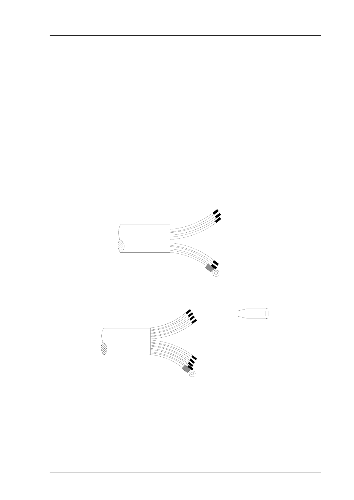
The cable wires are connected as shown in Figure 1.
HMP45D
HMP45A
YEL OUTPUT
0...1V=-40...+60 ˚C
BLU V+ 7...35VDC
BRN OUTPUT
0...1V=0... 100%RH
VIO GND
RED GND (SENSE)
GREY (SHIELD)
YEL
WHT
GRN
BLK
GREY (SHIELD)
Pt100
Pt100
Pt100
Pt100
BLU 7...35VDC
BRN OUTPUT 0...1V=0...100%RH
VIO GND
RED GND (SENSE)
Figure 1 Wire colours
Pt100
SIGNAL GROUND is used for output signal in a differential measurement. With
SIGNAL GROUND, the cable can be extended up to 100 metres without
disturbing the measurement accuracy. When outputs are not measured against
SIGNAL GROUND, connect GROUND and SIGNAL GROUND to the same point.
1
Page 4

HMP45A and HMP45D
Operating Manual U274en-1.2
3. CALIBRATION AND MAINTENANCE
Calibration and maintenance of the probes should be performed at regular
intervals, depending on the conditions of use and desired accuracy. The
recommended calibration interval is one year.
The HMP45A/D probes are easy to maintain and calibrate. The probe consists
of a probe head and a handle with cable. All calibration electronics are in the
probe head which can be disconnected from the handle without disconnecting
the wires (see Figure 2). The handles of all HMP45A and HMP45 probes are
fully interchangeable. If you wish to continue the measurement immediately,
you can insert a calibrated probe head in place of the disconnected one; this
way, the measurement is interrupted for less than a minute.
3.1 Reading the outputs during calibration
adjustment trimmers:
W = wet D = dry
(T = temperature; for
D
W
T
factory use only!)
pull the probe head
off the handle
NOTE:
remove the O-ring if you
connect the probe directly
to the HMI41 indicator
ENTERMODE HOLD ON/OFF
HMI41HMH45
Figure 2 Adjustment trimmers and probe head connection/disconnection
In calibration, the HMP45A/D output is normally read from the output cables.
The HMP45A probe head can also be checked with Vaisala’s HMI41 indicator
(see Figure 2); the probe head can be connected either to the HMH45 handle,
or directly to the HMI41 indicator. However, note that if you connect the
probe head directly to the HMI41, you must first remove the O-ring. Measured
humidity and temperature appear on the HMI41 display.
A simple field check can also be performed when there seems to be something
wrong with the measurement system. It is sufficient to compare the HMP45A
reading with the reading measured by a calibrated reference probe head. Check
2
Page 5

HMP45A and HMP45D
U274en-1.2 Operating Manual
the ambient relative humidity and temperature level with the reference probe
head, and then connect the HMP45A probe head on the HMH45 handle and
check the output readings.
Prepare the HMI41 indicator for measurements with the HMP45A probe head
as follows: turn the HMI41 indicator on and within 1-2 seconds press
simultaneously buttons ENTER and MODE until the text SEtUP appears on
the display.
Wait a few seconds, and the text Unit appears; press ENTER repeatedly until
a text similar to the following appears on the display:
set
Select PROBE TYPE 3 with buttons ▲ (number up) or ▼ (number down) and
turn the indicator off. Turn it on again by pressing the ON/OFF button. After a
few seconds, the relative humidity and temperature readings appear
automatically on the display. The HMP45D cannot be used w ith the HMI41
indicator as the passive temperature signal results in error messages on
the HMI41.
3.2 Humidity calibration
For a high-accuracy two-point calibration use a Vaisala HMK15 or HMK13B
calibrator and saturated salt solutions as described in the respective manuals.
Leave the calibrator, the HMI41 and the probe head in the same space for at
least four hours so that their temperatures have time to equalize. Unscrew the
plastic grid of the probe.
The calibration is done first for the dry end and then for the wet end by
adjusting trimmer potentiometers marked “D” (dry, <50 %RH) and “W” (wet,
>50 %RH). The potentiometers are located under a protective plug; see Figure
2. Use a ceramic screw driver with 2.5 mm blade for adjusting the
potentiometers. Note: if zero point is calibrated in Nitrogen (N2), the
minimum output signal of 0.008 V corresponds to a relative humidity of 0.8
%RH.
Greenspan’s calibration table
Temperature °C 15 20 25 30 35
LiCl %RH *) 11.3 11.3 11.3 11.3
NaCl %RH 75.6 75.5 75.3 75.1 74.9
K2SO
4
*) Do not use or store the LiCl solution in temperatures below +18°C as its humidity
equilibrium may change permanently
%RH 97.9 97.6 97.3 97.0 96.7
3
Page 6

HMP45A and HMP45D
Operating Manual U274en-1.2
As the D (dry) and W (wet) adjustments may affect each other, check again
the humidity reading at the low end. If necessary, repeat the adjustments in
both the low and the high humidity points until the reading is correct.
3.3 Changing the HUMICAP®180 humidity sensor
Unscrew the filter. Remove the damaged sensor and mount a new
HUMICAP®180 humidity sensor in its place. Handle the sensor with care.
Calibrate the probe using a two-point calibration procedure. Note that if the
probe is not calibrated, the accuracy is still better than ±7 %RH.
4. SPARE PARTS AND ACCESSORIES
Order code Description
HUMICAP180
18921 Temperature sensor Pt 1000 IEC 751 1/3 Class B (HMP45A)
19159 Temperature sensor Pt 100 IEC 751 1/3 Class B (HMP45D)
2787HM Membrane filter (standard)
6685 Sintered filter 37 µm
6686 Sintered filter 216 µm
6597 Plastic grid
HMP45ASP HMP45A probe head
HMP45DSP HMP45D probe head
HMH45ASP Probe handle for HMP45A and HMP45D
HMI41 Humidity and temperature indicator
HMH45 Probe handle for HMP45A with a connector to HMI41
HMK11 Humidity Calibrator
HMK13B Humidity Calibrator
Humidity sensor
5. TECHNICAL DATA
5.1 Humidity (HMP45A & HMP45D)
Measurement range 0.8...100 %RH
Output scale 0...100 %RH equals 0-1 VDC
Accuracy at +20 °C (including non-linearity and hysteresis):
against factory references ±1 %RH
field calibration against references ±2 %RH (0...90 %RH)
Typical long-term stability better than 1 %RH per year
Temperature dependence ±0.05 %RH/°C
Response time (90%) at +20 °C 15 s with membrane filter
Humidity sensor HUMICAP
4
±3 %RH (90...100 %RH)
®
180
Page 7

HMP45A and HMP45D
C
U274en-1.2 Operating Manual
5.2 Temperature
HMP45A
Measurement range -39.2...+60 °C
Output scale -40...+60 °C equals 0...1 VDC
Accuracy at 20°C ±0.2 °C
Accuracy over the whole measurement range:
0.5
0.4
0.3
0.2
0.1
0
-0.1
-0.2
-0.3
-0.4
-0.5
-30-40
-20
-10 0
10
20
30
40
50
60
°
Temperature sensor Pt 1000 IEC 751 1/3 Class B
HMP45D
Measurement range -40...+60 °C
Output signal resistive four wire connection
Temperature sensor Pt 100 IEC 751 1/3 Class B
5.3 General
Operating temperature range -40...+60 °C
Storage temperature range -40...+80 °C
Supply voltage 7...35 VDC
Settling time 500 ms
Power consumption < 4 mA
Output load >10 kohm (to ground)
Weight 350 g (including package)
Cable length 3.5 m
Housing material ABS plastic
Housing classification (electronics) IP 65 (NEMA 4)
Sensor protection (standard) membrane filter, part no. 2787HM
Dimensions in mm (inches):
5
Page 8

HMP45A and HMP45D
Operating Manual U274en-1.2
240 (9.45)
118 (4.65)
A
3500 (137.8)
24
A
A-A
20.5
(0.81)
(0.94)
5.4 Electromagnetic compatibility
5.4.1 Emissions
Radiated interference, test setup according to EN55022
5.4.2 Immunity
Test: Test setup Performance:
according to:
24
(0.94)
18.5
( 0.72)
REMOVABLE
PROBE HEAD
(132 mm)
Radiated interference IEC 1000-4-3 HMP45A level 1 (3V/m)
HMP45D level 3 (10 V/m)
Electrostatic discharge IEC 801-4 level 4 (HMP45A&D)
GUARANTEE
Vaisala issues a guarantee for the material and workmanship of this product
for one (1) year from the date of delivery. Damage due to exceptional
operating conditions, careless handling or misapplication will void the
guarantee. Detailed warranty information is given in the Warranty and the
Standard Conditions of Sale of Vaisala Oy.
6
Page 9

Page 10

*U274
EN
*
www.vaisala.com
 Loading...