

Page 1
QUICK REFERENCE GUIDE
Vaisala CARBOCAP® Carbon
Dioxide and Temperature
Transmitter GMW116
GENERAL
The Vaisala CARBOCAP® Carbon Dioxide and Temperature
Transmitter GMW116 measures the temperature and carbon
dioxide level in indoor spaces, and sends this information to the
ventilation system. The ventilation can then be controlled more
accurately, resulting in better indoor air and lowered energy
consumption.
Since the GMW116 constantly measures the temperature, there
is no need for temperature compensation in carbon dioxide
measurement.
INSTALLATION
1. Select the Location for a Transmitter
Select a location for the transmitter using the following criteria:
- The conditions at the location should represent well the area
of interest. Avoid placing the transmitter near heat sources,
ventilation, or in direct sunlight. Do not install the transmitter
on the ceiling.
- Check that the location has easy access to power supply
wiring.
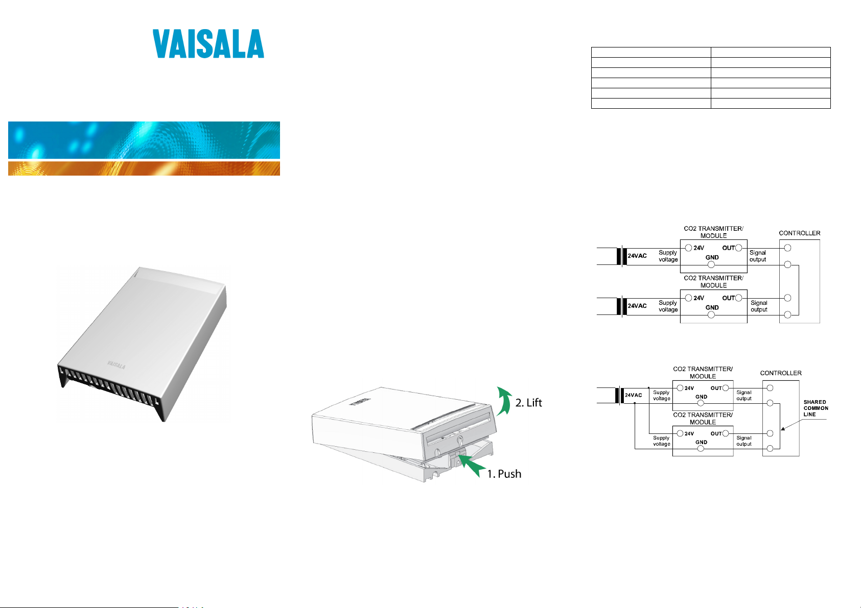
2. Open the Transmitter
The GMW116 transmitters are delivered closed. Open the
transmitter as follows:
1. Push down on the plastic clip using a flat head screwdriver.
The clip is visible through the ventilation slit at the top of the
transmitter.
2. Lift the top of the cover to remove it.
ELECTRICAL CONNECTIONS
Vin+ Power supply (+) 24 VDC/VAC
0 Power supply (-)
CH1 CO2 Signal (+) 0... 10 V
GND Signal (-)
CH2 Temperature Signal (+) 0... 10 V
GND Signal (-)
3. Connect the Power Supply
The power cable can be inserted from the top, bottom, or center
of the mounting base. Insert the power cable from the cable feed
that is most convenient (top or center preferred), and connect the
wires to the screw terminals. Avoid looping the cable over the
ventilation holes at the bottom of the transmitter, as this would
interfere with temperature and humidity measurement.
The transmitter operates on 24 VAC or 15 ... 36 VDC
Figure 2 Connection of Separate AC Supplies (Recommended)
– Compact, wall-mounted carbon
dioxide and temperature transmitter
for demand-controlled ventilation
– Ideal for HVAC applications
– Advanced single-beam dual
wavelength measurement with no
moving parts
– Incorporates the Vaisala
CARBOCAP® Sensor
© Vaisala 2010. All rights reserved.
*M211092EN*
Figure 3 Connection of Single AC supply to Several Transmitters
Figure 1 Opening the Transmitter
Page 2
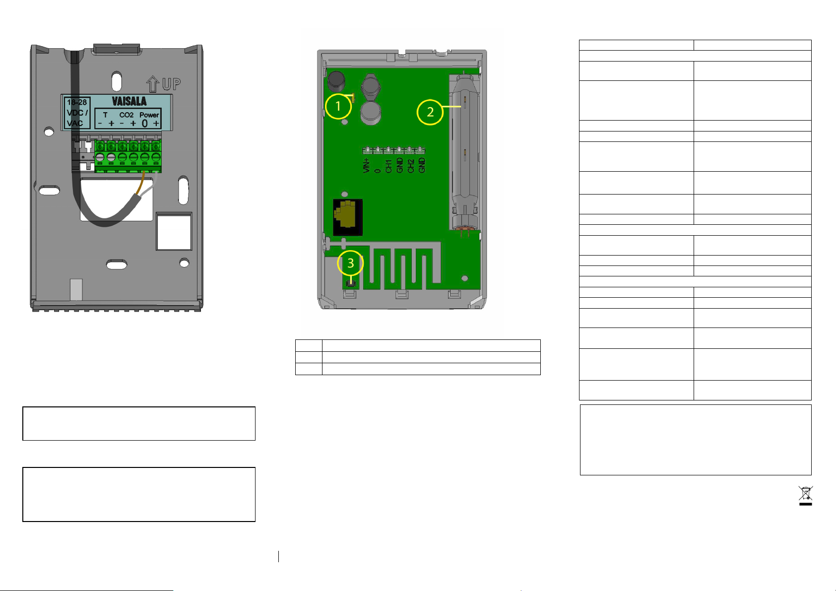
Figure 4 Surface routing of the power cable
4. Install the Mounting Base
Use the mounting holes to attach the mounting base securely to
the desired location. Use at least two screws (not included). Note
the correct orientation: the arrow on the mounting base must
point straight up after installation.
NOTE The accuracy of the temperature
measurement depends directly on the
temperature dynamics of the wall material.
NOTE A through-wall mounting for the power
cable is also possible. When tubes are used
in through-wall mounting, make sure the
tubes are properly sealed to avoid false
measurements.
1 Diag D nostics LE
2 CO2 sensor
3 Temperature sensor
Figure 5 GMW116 Cover
5. Connect the Cover to the Base
Place the cover on the mounting base and close it so that the
plastic clip snaps into place. Make sure that the pins mate with
the holes on the screw connector.
6. Check the Diagnostics LED
The transmitter has a diagnostics LED on the component board
that is visible through the front ventilation hole when the
transmitter is closed.
Green LED is lit during normal operation and will blink if there
is an internal error, for example a sensor fault.
TECHNICAL DATA
DescripProperty Va
Performance
Measurement ranges 0 ... 2000 ppm CO
Measurement accuracy
(incl. repeatability, nonlinearity and calibration
uncertainty)
Long-term stability ± 5 % of range / 5 years
Response time 1 min
Pressure dependence of
reading
Temperature measurement
accuracy
Warm-up time 1 min
Product lifetime > 10 years
Operating environment
Operating temperature
range
Operating humidity range 0 ... 85 %RH
Operating pressure range 700 hPa ... 1200 hPa
Inputs and outputs
Operating voltage 24 V (±20 %) AC/DC
Power consumption < 2 W
Connections Screw terminals, wire size
Outputs
analog 2 x (0 ... 10 V)
Recommended external
load
voltage output > 10 kΩ
Electromagnetic
compatibility
GUARANTEE
Vaisala issues a guarantee for the material and workmanship
of this product under normal operating conditions for two (2)
years from the date of delivery. Exceptional operating
conditions, damage due to careless handling and
misapplication will void the guarantee.
tion / lue
0 ...50° C T
±(2.0 % of range + 2 % of
reading)
+ 0.15 % of reading / hPa
(typical)
± 0.7° C at 25° C
0 … +50° C
0.22 ... 1.5 mm
EN61326-1:
Generic Environment
2
2
Visit our Internet pages at www.vaisala.com
M211092EN-A
 Loading...