

Page 1
3-854-213-12 (1)
Remote Control Unit
Operating Instructions
Mode d’emploi ________________________________________
Manual de instrucciones _________________________________
Gebrauchsanweisung __________________________________
__________________________________
GB
FR
ES
DE
RM-BR300
© 2004 Sony Corporation
Page 2

Owner’s Record
The model and serial numbers are located on the bottom.
Record the serial number in the space provided below.
Refer to these numbers whenever you call upon your
Sony dealer regarding this product.
Model No. RM-BR300
Serial No.
WARNING
To reduce a risk of fire or electric shock,
do not expose this product to rain or
moisture.
To avoid electrical shock, do not open the
cabinet. Refer servicing to qualified
personnel only.
WARNING
Use the Sony MPA-AC1 AC power adapter provided
with this equipment as a power supply source. Any other
power sources may result in hazards such as a fire.
Disconnect device of this equipment is the mains plug of
the AC adapter.
The mains plug on this equipment must be used to
disconnect mains power.
Please ensure that the socket outlet is installed near the
equipment and shall be easily accessible.
In the event of abnormal operations, disconnect the
mains plug.
IMPORTANT
Nameplate is located on the bottom.
– Reorient or relocate the receiving antenna.
– Increase the separation between the equipment and
receiver.
– Connect the equipment into an outlet on a circuit
different from that to which the receiver is connected.
– Consult the dealer or an experienced radio/TV
technician for help.
If you have any questions about this product, you may
call:
Sony's Business Information Center (BIC) at
1-800-686-Sony (7669)
or Write to: Sony Customer Information Services
Center
6900-29, Daniels Parkway, PMB 330
Fort Myers, Florida 33912
Declaration of Conformity
Trade Name: SONY
Model No: RM-BR300
Responsible Party: Sony Electronics Inc.
Address: 16450 W. Bernardo Dr, San
Diego, CA 92127 U.S.A.
Telephone Number:858-942-2230
This device complies with part 15 of the FCC Rules.
Operation is subject to the following two conditions:
(1) This device may not cause harmful interference,
and
(2) this device must accept any interference received,
including interference that may cause undesired
operation.
You are cautioned that any changes or modifications not
expressly approved in this manual could void your
authority to operate this equipment.
ATTENTION
The electromagnetic fields at the specific frequencies
may influence the picture of this unit.
For customers in the U.S.A.
This equipment has been tested and found to comply
with the limits for a Class B digital device, pursuant to
Part 15 of the FCC Rules. These limits are designed to
provide reasonable protection against harmful
interference in a residential installation. This equipment
generates, uses, and can radiate radio frequency energy
and, if not installed and used in accordance with the
instructions, may cause harmful interference to radio
communications. However, there is no guarantee that
interference will not occur in a particular installation. If
this equipment does cause harmful interference to radio
or television reception, which can be determined by
turning the equipment off and on, the user is encouraged
to try to correct the interference by one or more of the
following measures:
The shielded interface cable recommended in this
manual must be used with this equipment in order to
comply with the limits for a digital device pursuant to
Subpart B of Part 15 of FCC Rules.
INTERFACE CABLE
This device requires shielded interface cables to comply
with FCC emission limits.
GB
2
Page 3

Table of Contents
Overview
Features ..................................................................4
Precautions ............................................................. 4
Location and Function of Parts ............................ 5
Available Functions for Sony VISCA Cameras . 8
Connections and Operations
Connections ............................................................ 9
Connecting a Camera Equipped with a VISCA
RS-232C Connector ......................................... 9
Connecting a Camera Equipped with a VISCA
RS-422 Connector .......................................... 10
Connecting Multiple Cameras Equipped with
VISCA RS-232C Connector .......................... 10
Connecting Multiple Cameras Equipped with
VISCA RS-422 Connector ............................. 11
Connecting the BRU-300/300P Optical Multiplex
Unit ................................................................. 12
Connecting a Video Switcher ........................... 13
Turning on the Power .......................................... 13
Storing the Camera Settings in Memory
– Presetting Feature ............................................. 14
Setting the Speed of the Camera Moving to a
Preset Position (BRC-300/300P and BRC-H700/
H700P only) ................................................... 15
GB
Appendix
Troubleshooting ................................................... 16
Specifications ........................................................ 17
Dimensions ....................................................... 17
Pin Assignments ............................................... 18
Using the VISCA RS-422 Connector Plug ...... 19
Table of Contents
GB
3
Page 4

Overview
Precautions
Overview
Features
The optical three-axis joystick allows
comfortable pan/tilt/zoom operations.
Easy operation of versatile camera
adjustments
Using the buttons on the unit, you can easily perform
various camera adjustments such as auto focusing, onepush auto focus adjustment, AE adjustment, one-push
auto white balance adjustment and backlight
compensation.
The VISCA RS-232C/RS-422 communication
interfaces allow high-speed, long-distance
communication.
The unit is capable of controlling up to seven cameras
connected in daisy chain.
A tally lamp input/contact output terminal (9pin connector plug) allows connection of a
video switcher.
Preset feature to save camera settings
The unit allows saving up to 16 combinations* of
camera settings such as pan/tilt/zoom positions and
other camera adjustment values in the memory of the
camera.
Operating or storing the unit in the following locations
may cause damage to the unit:
• Extremely hot or cold places (Operating temperature:
°C to +40°C [32°F to 104°F])
0
• Exposed in direct sunlight for a long time, or close to
heating equipment (e.g., near heaters)
• Close to sources of strong magnetism
• Close to sources of powerful electromagnetic
radiation, such as radios or TV transmitters
• Locations subject to strong vibration or shock
Ventilation
To prevent heat buildup, do not block air circulation
around the unit.
Transportation
When transporting the unit, repack it as originally
packed at the factory or in materials equal in quality.
Cleaning
• Use a soft, dry cloth to clean the external surfaces of
the unit. Stubborn stains can be removed using a soft
cloth dampened with a small quantity of detergent
solution, then wipe dry.
• Do not use volatile solvents such as alcohol, benzene
or thinners as they may damage the surface finishes.
Operating or storage location
* The number of positions to be saved differs depending
on the connected camera. (For the BRC-300/300P
3CCD Color Video Camera, 6 positions can be saved.)
Controllable Sony VISCA cameras
The unit can control the following cameras:
• BRC-300/300P 3CCD Color Video Camera
• BRC-H700/H700P HD 3CCD Color Video Camera
• EVI-D100/D100P Color Video Camera
• EVI-D70/D70P Color Video Camera
• EVI-D30/D30P Color Video Camera
• SNC-RZ30N/RZ30P Network Camera
Notes
• The operable functions are limited to those that the
camera is equipped with.
• This manual mainly explains the functions of the unit
for the BRC-300/300P camera.
When another camera is connected, refer to the
Operating Instructions supplied with the connected
camera for available functions.
GB
4
Features / Precautions
Page 5
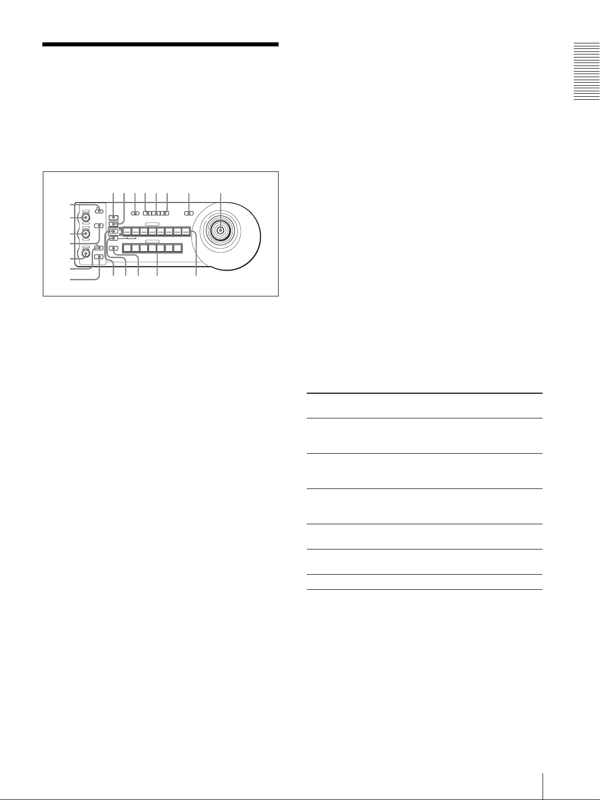
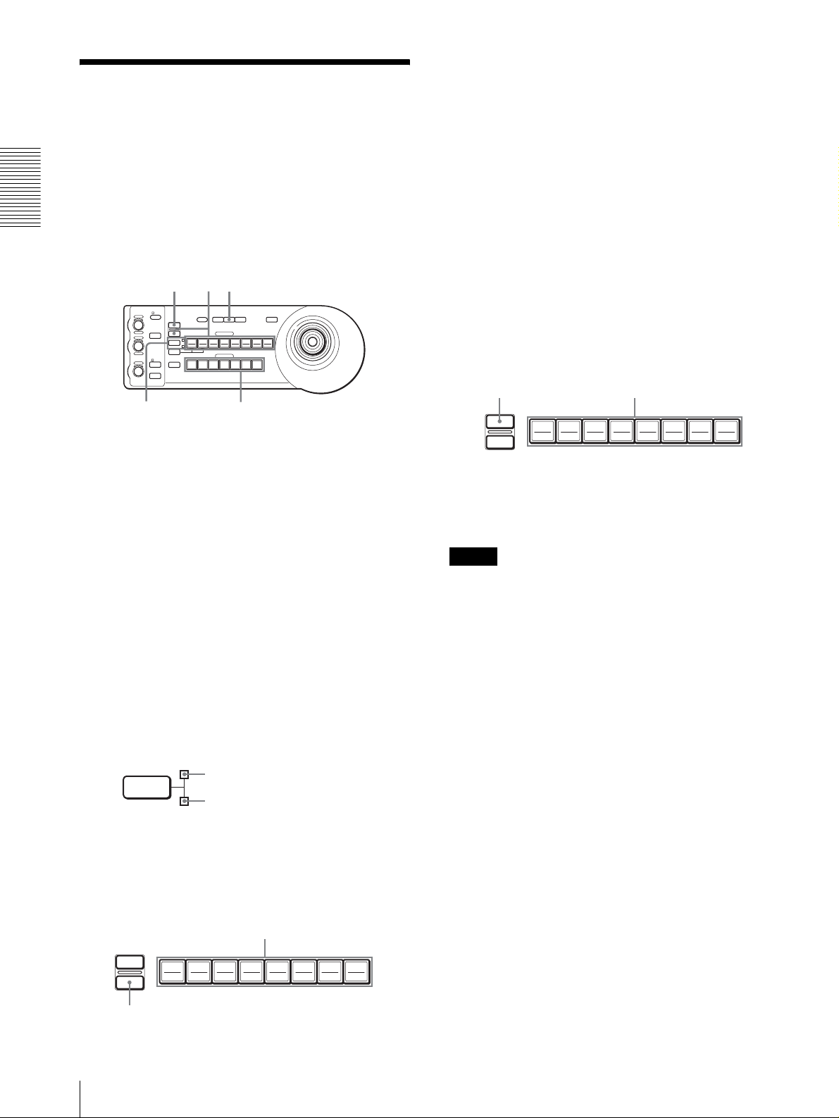
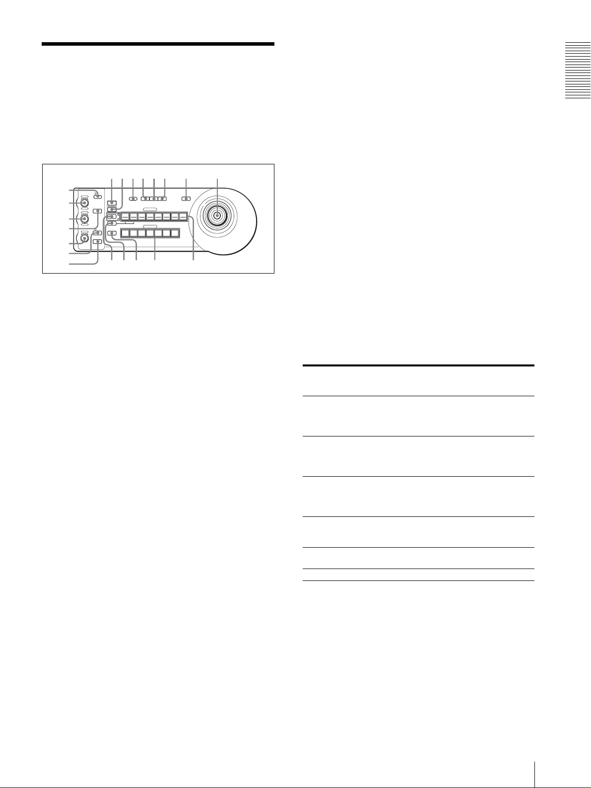
Location and Function
qhqjqkq
w
of Parts
This manual focuses on the operations of the RMBR300 when it is used with the BRC-300/300P or BRCH700/H700P camera.
Front
C BRIGHT/B control
When the brightness adjustment mode is
selected with the MODE button (with the
BRIGHT indicator lit:
This control adjusts the value of the brightness of
the camera, etc.
When the BRIGHT indicator is lit, the function of
the control varies according to the exposure mode
selected on the camera. For details, see “Functions
of the VALUE and BRIGHT controls” on page 5.
Overview
90qaqsqd qf qg
8
1
VALUE
2
3
4
5
– +
– +
NEAR FAR
LOCK
R
MODE
BRIGHT
B
AUTO
FOCUS
AUTO
MANUAL
ONE PUSH
AF
RESET
PRESET
SHIFT
DIRECTION
POWER
1
9
STD REV
L/R
1
PANEL
BLACK
PAN-TILT
ONE PUSH
LIGHT
LIGHT
RESET
AWB
POSITION
2
3114
5136147158
10
12
CAMERA
234567
MENU
16
6
7
l
;
A LOCK button and indicator
Press the LOCK button for more than one second,
and the LOCK indicator lights and the values set by
the VALUE/R, BRIGHT/B and FOCUS controls
are locked. (The indicators of the locked controls
are turned off.).
The AUTO/MANUAL button is also disabled.
Press the LOCK button for more than one second
again to unlock the controls and buttons.
B VALUE/R control
When the brightness adjustment mode is
selected with the MODE button (with the
VALUE indicator lit):
This control adjusts the value of the item
(SHUTTER or IRIS) selected on the camera.
When the VALUE indicator is lit, the function of
the control varies according to the exposure mode
selected on the camera. For details, see “Functions
of the VALUE and BRIGHT controls” on page 5.
When the white balance adjustment mode is
selected with the MODE button (with the R
indicator lit):
This control adjusts the R. GAIN (red gain) (except
the EVI-D30/D30P).
When the BRC-H700/H700P camera is connected,
the function of the control with the R indicator lit
varies according to the white balance mode selected
on the camera. For details, see “Functions of the R
and B controls for the BRC-H700/H700P camera”
on page 5.
When the white balance adjustment mode is
selected with the MODE button (with the B
indicator lit:
This control adjusts the B. GAIN (blue gain)
(except the EVI-D30/D30P).
When the BRC-H700/H700P camera is connected,
the function of the control with the B indicator lit
varies according to the white balance mode selected
on the camera. For details, see “Functions of the R
and B controls for the BRC-H700/H700P camera”
on page 5.
Functions of the VALUE and BRIGHT controls
The functions of the VALUE control and the BRIGHT
control change according to the exposure mode setting
on the camera, as follows:
Exposure mode
on the camera
FULL AUTO Not used Exposure
SHUTTER Pri Shutter speed
IRIS Pri Iris control Exposure
BRIGHT Not used Brightness level
MANUAL Shutter speed
GAIN Pri*** Gain control
* When the exposure compensation function is activated on
the camera.
** Iris + Gain control is possible for the BRC-H700/H700P
camera.
*** Available for the BRC-H700/H700P camera only
Function of
VALUE control
control
control
***
Function of
BRIGHT control
compensation level
control*
Exposure
compensation level
control*
compensation level
control*
control
Iris control**
Not used
Functions of the R and B controls for the BRCH700/H700P camera
When the white balance adjustment mode is selected
with the MODE button of this unit, the functions of the
R control and B control change according to the white
balance mode setting on the BRC-H700/H700P camera.
GB
Location and Function of Parts
5
Page 6

J PANEL LIGHT button
White balance
mode on the
camera
MANUAL Red gain control Blue gain control
Overview
AUTO, ONE
PUSH
Function of the
R control
Red WB SHIFT
control
Function of the
B control
Blue WB SHIFT
control
Press this button to illuminate all the POSITION
buttons and CAMERA buttons. Press the button
again to turn off the illumination.
K BACK LIGHT button
When the FULL AUTO exposure mode is selected
on the camera, press this button to enable the
D MODE button
Press this button to select the function of the
VALUE/R control and BRIGHT/B control.
When the brightness adjustment mode is selected,
the VALUE and BRIGHT indicators are lit.
When the white balance adjustment mode is
selected, the R and B indicators are lit.
E FOCUS control
This control is enabled when MANUAL is selected
with the AUTO/MANUAL button. Turn the control
counterclockwise (toward NEAR) to focus on a
near subject, and clockwise (toward FAR) to focus
on a far subject.
backlight compensation function of the camera.
Press it again to disable the function.
For the BRC-H700/H700P camera, hold down the
SHIFT button and press this button to enable the
spotlight compensation function of the camera.
This function adjusts the exposure to a darker level
if a portion of the shooting object is illuminated.
To disable the spotlight compensation, hold down
the SHIFT button and press this button again.
L PAN-TILT RESET button
Press this button to reset the pan/tilt position of the
camera to the initial conditions.
F AUTO/MANUAL button and AUTO indicator
Press this button to select focus mode AUTO or
MANUAL.
When AUTO is selected, the AUTO indicator lights
and the camera focuses automatically on the subject
in the center of the screen. The FOCUS control and
the ONE PUSH AF button are disabled.
When MANUAL is selected, the FOCUS control
and the ONE PUSH AF button are enabled (with
the FOCUS indicator lit).
G ONE PUSH AF button
This button is enabled when MANUAL is selected
with the AUTO/MANUAL button. Press the button
to perform the one-push auto focus function (except
the EVI-D30/D30P).
H RESET button
Hold down this button and press one of the
POSITION buttons, and the memory of the camera
corresponding to the pressed POSITION button is
cleared to the factory-preset conditions.
When multiple cameras are connected, the camera
addresses are set by holding down this button and
pressing the POWER button.
I PRESET button
Hold down this button and press one of the
POSITION buttons, and the current camera settings
are stored in the memory of the camera
corresponding to the pressed POSITION button.
M ONE PUSH AWB button
When the ONE PUSH white balance mode is
selected on the camera, press this button to perform
the one-push white balance adjustment.
N MENU button
For the BRC-300/300P or BRC-H700/H700P
camera, press this button for about one second to
display the menu of the camera, return to the main
menu or turn off the menu.
For other cameras, press this button for about one
second to turn the on-screen data display on or off.
O Joystick
The joystick is used for pan/tilt and zoom
operations. Select the camera you want to control
using the CAMERA buttons and operate the
joystick.
Panning and tilting
When you incline the joystick right and left, the
camera pans. When you incline it forward or
backward, the camera tilts.
The pan/tilt speed changes according to the angle of
the inclination.
When you release the joystick, the camera
movement stops.
Zooming
When you turn the dial on the upper part of the
joystick clockwise, the subject becomes larger
(zoom in). When you turn it counterclockwise, the
subject becomes smaller (zoom out).
GB
6
Location and Function of Parts
Page 7
To face the camera back to the front
When you press the button on the top of the joystick
for one or two seconds with or without the menu
displayed, the pan/tilt/zoom are reset and the
camera returns to the front.
P SHIFT button and indicators
Press this button for more than one second to select
the function of the POSITION buttons for positions
1 to 8 or positions 9 to 16.
The upper indicator lights for positions 1 to 8, and
the lower indicator for positions 9 to 16.
For the BRC-H700/H700P camera, hold down the
SHIFT button and press one of the POSITION
buttons. The lower indicator will light and you can
use the POSITION buttons for positions 9 to 16. If
you release the SHIFT button, the upper indicator
will light and the POSITION buttons can be used
for positions 1 to 8.
Q L/R DIRECTION button
The camera is preset to face toward the right
whenever the joystick is inclined to the right. Hold
down this button and press POSITION button 2
(REV) to reverse the pan direction to the direction
in which you incline the joystick. To reset the
direction, hold down this button and press
POSITION button 1 (STD).
the camera model and the functions of positions 7 to 16
of the POSITION buttons change as in the following
table. This allows you the direct control of the camera
without connecting to a computer.
POSITION
button
Position 7 Automatic Exposure – Full Auto mode
Position 8 Automatic Exposure – Bright mode
Position 9 Digital zoom – ON
Position 10 Digital zoom – OFF
Position 11 Auto White Balance mode
Position 12 Manual White Balance mode
Position 13 One Push White Balance mode
Position 14 Auto Tracing White Balance (ATW) mode
Position 15 IR Cut-Removable (ICR) – ON
Position 16 IR Cut-Removable (ICR) – OFF
Function
For details on each function, refer to the Technical
Manual of the camera.
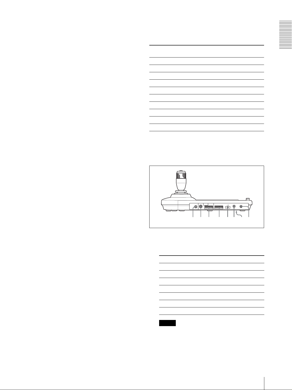
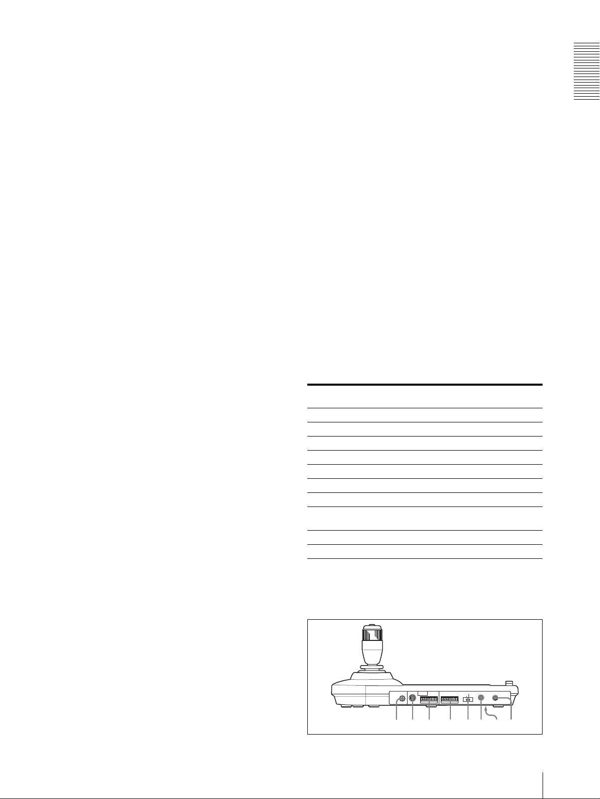
Rear/Bottom
Overview
R POWER button
Press this button to light the CAMERA button(s)
corresponding to the status of the connected
camera(s).
Blue: The power of the camera is on.
Yel lo w g re e n : The camera is in standby mode.
Off: No camera is connected.
Hold down this button and press CAMERA button
1 to 7 to turn on/off the power of the camera
corresponding to the pressed button.
S CAMERA buttons
Press one of the buttons to select the camera from
among those connected. The selected CAMERA
button lights in blue.
T POSITION buttons
You can store various camera settings such as the
pan, tilt and zoom positions to the memory of the
camera corresponding to each POSITION button,
and load the settings in the memory.
Functions of the POSITION buttons for
the EVI-D100/D100P and EVI-D70/D70P
cameras
When the EVI-D100/D100P or EVI-D70/D70P camera
is connected to this unit, the unit automatically detects
MODE
RS-232C
RS-422 ON/OFF
VISCA
1919
TALLY/CONTACT
CONTACT(TALLY)
TALLY
CONTACT DC IN 12V
!
ws wd wf wg wh wj wkwa
U MODE selector
Select the position corresponding to the VISCAcontrollable camera to be connected.
Switch position Camera mode
0 Automatically selected (default)
1 BRC-300/300P
2 EVI-D70/D70P
3 EVI-D100/D100P
4 EVI-D30/D30P
5 SNC-RZ30N/RZ30P
6 BRC-H700/H700P
Notes
• Use position 1 to 4 when all the connected
cameras are of the same model.
• Be sure to use position 5 for the SNC-RZ30N/
RZ30P.
Location and Function of Parts
GB
7
Page 8

V VISCA RS-232C connector
Connect to the VISCA RS-232C IN connector of
the camera or the Optical Multiplex Unit.
CONTACT (TALLY): The contact output
corresponding to the camera address selected with
this unit is short-circuited against the connected
switcher and the tally lamp of the camera selected
W VISCA RS-422 connector
Overview
Connect to the VISCA RS-422 connector of the
camera or the Optical Multiplex Unit.
An RS-422 connector plug is attached at the
with the connected switcher lights.
wh DC IN 12V connector
Connect the supplied AC power adaptor.
factory.
wj DIP switches (bottom)
X TALLY/CONTACT connector
This connector is used for the tally lamp input or the
Switch 1 (RS-232C/RS-422 selector)
Set to ON for RS-422, or OFF for RS-232C.
contact output.
Select the function of the connector using the
TALLY/CONTACT selector.
Switch 2 (Communication baud rate selector)
Set to ON for 38400bps, or OFF for 9600bps.
An RS-422 connector plug is attached at the
factory.
wk ON/OFF switch
Press this switch to turn on/off this unit.
Y TALLY/CONTACT selector
Select the function of the TALLY/CONTACT
Note
connector.
TA LLY: The tally lamp of the camera selected
with the connected switcher lights.
Set the switches before you turn on the power of this
unit. Otherwise, the setting is not effective.
CONTACT: The contact output corresponding to
the camera address selected with this unit is shortcircuited against the connected switcher.
Available Functions for Sony VISCA Cameras
The functions of the controls, buttons and connectors in the following list differ depending on the connected camera
model. The functions of the other parts are the same for all the camera models.
Parts BRC-300/
300P, BRC-
H700/H700P
B VALUE/R control a a a
C BRIGHT/B control a a a
G ONE PUSH AF button a a a
L PAN-TILT RESET button a a a a
N MENU button a a a a
R POWER button a a a a
S CAMERA buttons a a a a
W VISCA RS-422 connector a
a: available, ×: not available
EVI-D100/
D100P
×
EVI-D70/
D70P
a
EVI-D30/
D30P
×
×
×
× ×
SNC-RZ30N/
RZ30P
a
a
a
×
×
×
×
GB
8
Location and Function of Parts
Page 9
Connections and Operations
Note
When using the VISCA RS-232C connectors, check that
the DIP switch on the bottom of this unit (page 8) is set
to RS-232C.
Connections
This section focuses on the connection examples for the
BRC-300/300P camera. For connections with other
cameras, refer to the Operating Instructions supplied
with the camera you will connect.
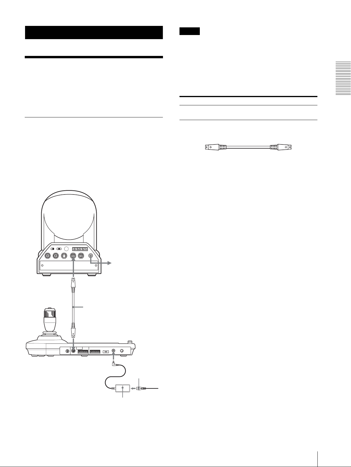
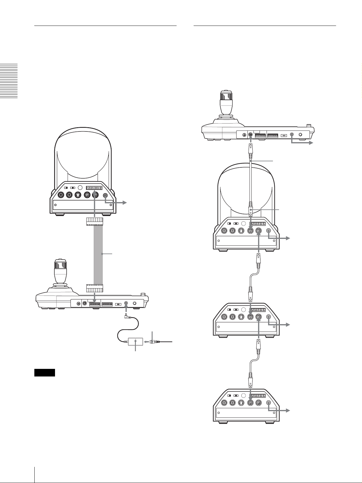
Connecting a Camera Equipped
with a VISCA RS-232C Connector
1
Connect this unit to the camera using the RS-232C
connecting cable supplied with this unit.
2
Connect this unit to an AC outlet using the supplied
AC power adaptor and AC power cord.
Camera BRC-300/300P
Connecting cables
Use the following connecting cable to connect devices
in this system.
Cable Part No. Number
RS-232C cable
(3m (10feet))
RS-232C cable
1-590-879-3X 1
Connections and Operations
OFF ON
EXT SYNC IN
IR SELECT
75
VIDEO S VIDEO
1 2 3
R
1 2 3 4 5 6 7 8 9
VISCA RS-422
!
IN VISCA RS-232C OUT
DC IN
12V
VISCA RS-232C IN
RS-232C cable (supplied)
(SONY: 1-590-879-3X)
VISCA RS-232C
DC IN 12V
AC power adaptor
MPA-AC1 (supplied)
to AC outlet
AC power cord
(supplied)
to AC outlet
Connections
GB
9
Page 10
Connecting a Camera Equipped
with a VISCA RS-422 Connector
You can use the VISCA RS-422 connectors to connect
this unit to the camera instead of the VISCA RS-232C
connectors. Use of the VISCA RS-422 connectors
allows the connection up to 1,200 m (3,937 feet) away.
Prepare the connecting cable using the RS-422
connector plugs that come with this unit.
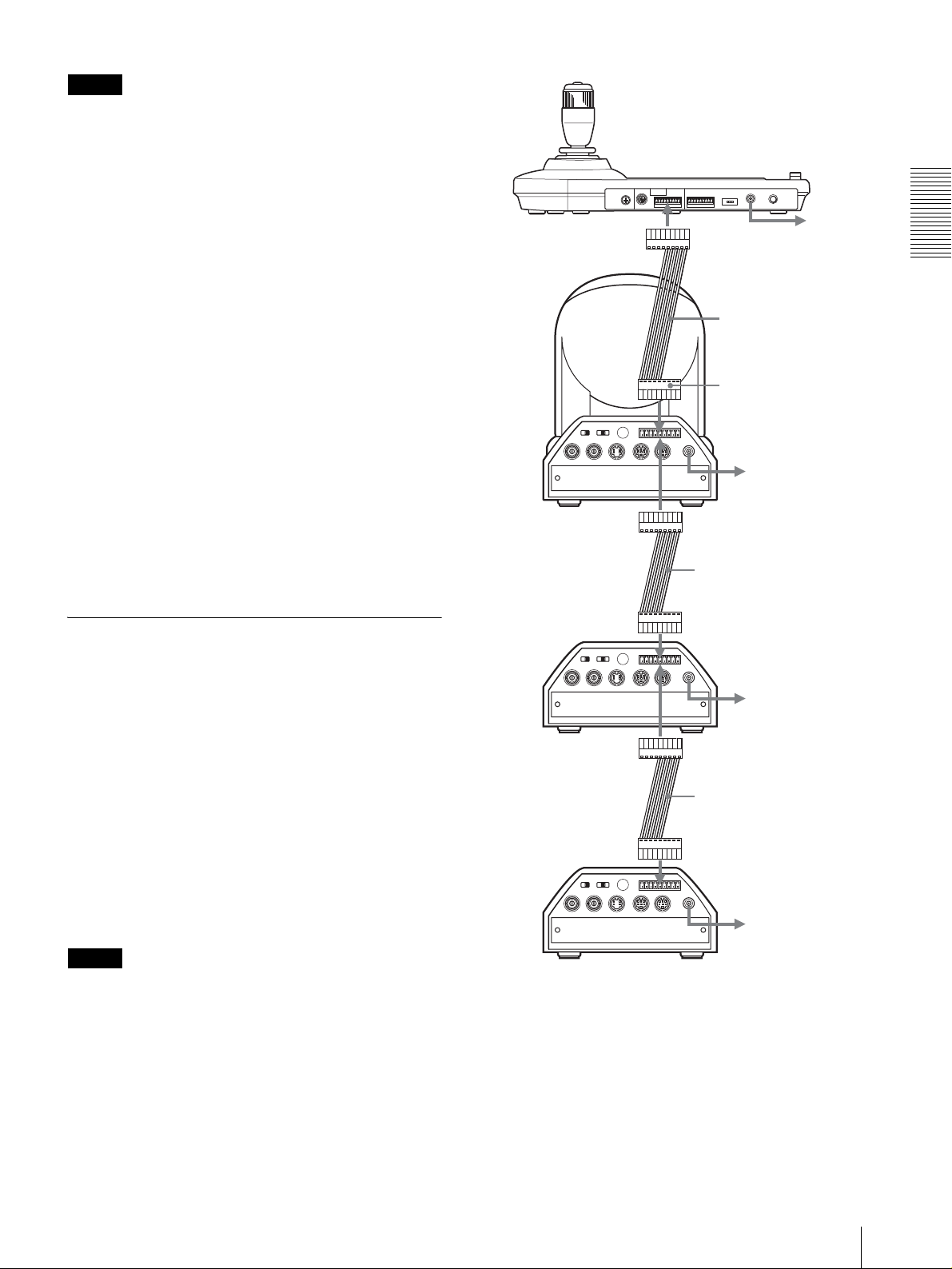
Connecting Multiple Cameras
Equipped with VISCA RS-232C
Connector
Connections with the VISCA RS-232C cables (cross
type) enable control of up to seven cameras with a single
RM-BR300 Remote Control Unit.
Connections and Operations
For making the cable, refer to the pin assignments of the
VISCA RS-422 connector (page 18).
For the use of the RS-422 connector plugs, see page 19.
Camera BRC-300/300P
to AC outlet
VISCA RS-422
VISCA RS-422 cable
VISCA RS-232C
Camera BRC300/300P
EXT SYNC IN
First camera
OFF ON
75
1 2 3
IR SELECT
VIDEO S VIDEO
R
1 2 3 4 5 6 7 8 9
IN VISCA RS-232C OUT
RS-232C cable (supplied)
(SONY: 1-590-879-3X)
to VISCA RS-232C IN
VISCA RS-422
!
DC IN
12V
VISCA RS-232C OUT
to AC outlet
to AC outlet
VISCA RS-422
DC IN 12V
AC power cord
(supplied)
to AC outlet
AC power adaptor
MPA-AC1 (supplied)
Notes
• When using the VISCA RS-422 connectors, check
that the DIP switch on the bottom of this unit (page 8)
is set to RS-422.
• When the connections using the VISCA RS-422
connectors are made, the VISCA RS-232C connection
is not available.
RS-232C cable
VISCA RS-232C IN
R
1 2 3 4 5 6 7 8 9
1 2 3
OFF ON
IR SELECT
EXT SYNC IN
75
VIDEO S VIDEO
VISCA RS-422
IN VISCA RS-232C OUT
Second camera
RS-232C cable
VISCA RS-232C IN
R
1 2 3 4 5 6 7 8 9
1 2 3
OFF ON
IR SELECT
EXT SYNC IN
75
VIDEO S VIDEO
VISCA RS-422
IN VISCA RS-232C OUT
Third to Seventh camera
!
DC IN
12V
to AC outlet
VISCA RS-232C OUT
!
DC IN
12V
to AC outlet
GB
10
Connections
Page 11
Note
When using the VISCA RS-232C connectors, check that
the DIP switch on the bottom of this unit (page 8) is set
to RS-232C.
To assign camera addresses
Before operating, you must assign the camera addresses
to the connected cameras as follows. Then you can
switch the camera to be controlled simply by pressing
the corresponding CAMERA button.
1
Turn on the power of all the connetcted cameras
and this unit.
2
Hold down the RESET button and press the
POWER button on this unit.
The unit recognizes the connected cameras and
assigns them camera addresses 1 to 7 automatically
in the connected order.
3
Press the POWER button on this unit and check that
the CAMERA buttons light.
The number of the lit CAMERA buttons indicates
how many cameras have the addresses assigned.
Now you can switch the camera you want to control
by pressing the CAMERA button.
Camera
BRC-300/300P
1 2 3
OFF ON
IR SELECT
75
EXT SYNC IN
VIDEO S VIDEO
First camera
R
IN VISCA RS-232C OUT
1 2 3 4 5 6 7 8 9
VISCA RS-422
VISCA RS-422
VISCA RS-422 cable
to VISCA RS-422
!
DC IN
12V
to AC outlet
VISCA RS-422
VISCA RS-422 cable
to AC outlet
Connections and Operations
Connecting Multiple Cameras
Equipped with VISCA RS-422
Connector
Connection via the VISCA RS-422 connectors enables
control of multiple cameras. This allows the connection
up to 1,200 m (3,937 feet) away.
Prepare the connecting cable using the RS-422
connector plug that comes with this unit.
For making the cable, refer to the pin assignments of the
VISCA RS-422 connector (page 18).
For the use of the RS-422 connector plugs, see page 19.
For the wiring diagram of VISCA RS-422 connection,
refer to the Operating Instructions supplied with the
BRC-300/300P.
Notes
• When using the VISCA RS-422 connectors, check
that the DIP switch on the bottom of this unit (page 8)
is set to RS-422.
• When the connections using the VISCA RS-422
connectors are made, the VISCA RS-232C connection
is not available.
R
1 2 3 4 5 6 7 8 9
1 2 3
OFF ON
IR SELECT
EXT SYNC IN
75
VIDEO S VIDEO
VISCA RS-422
IN VISCA RS-232C OUT
Second camera
R
1 2 3 4 5 6 7 8 9
1 2 3
OFF ON
IR SELECT
EXT SYNC IN
75
VIDEO S VIDEO
VISCA RS-422
IN VISCA RS-232C OUT
Third to Seventh camera
VISCA RS-422
!
DC IN
12V
to AC outlet
VISCA RS-422
VISCA RS-422 cable
VISCA RS-422
!
DC IN
12V
to AC outlet
Connections
11
GB
Page 12
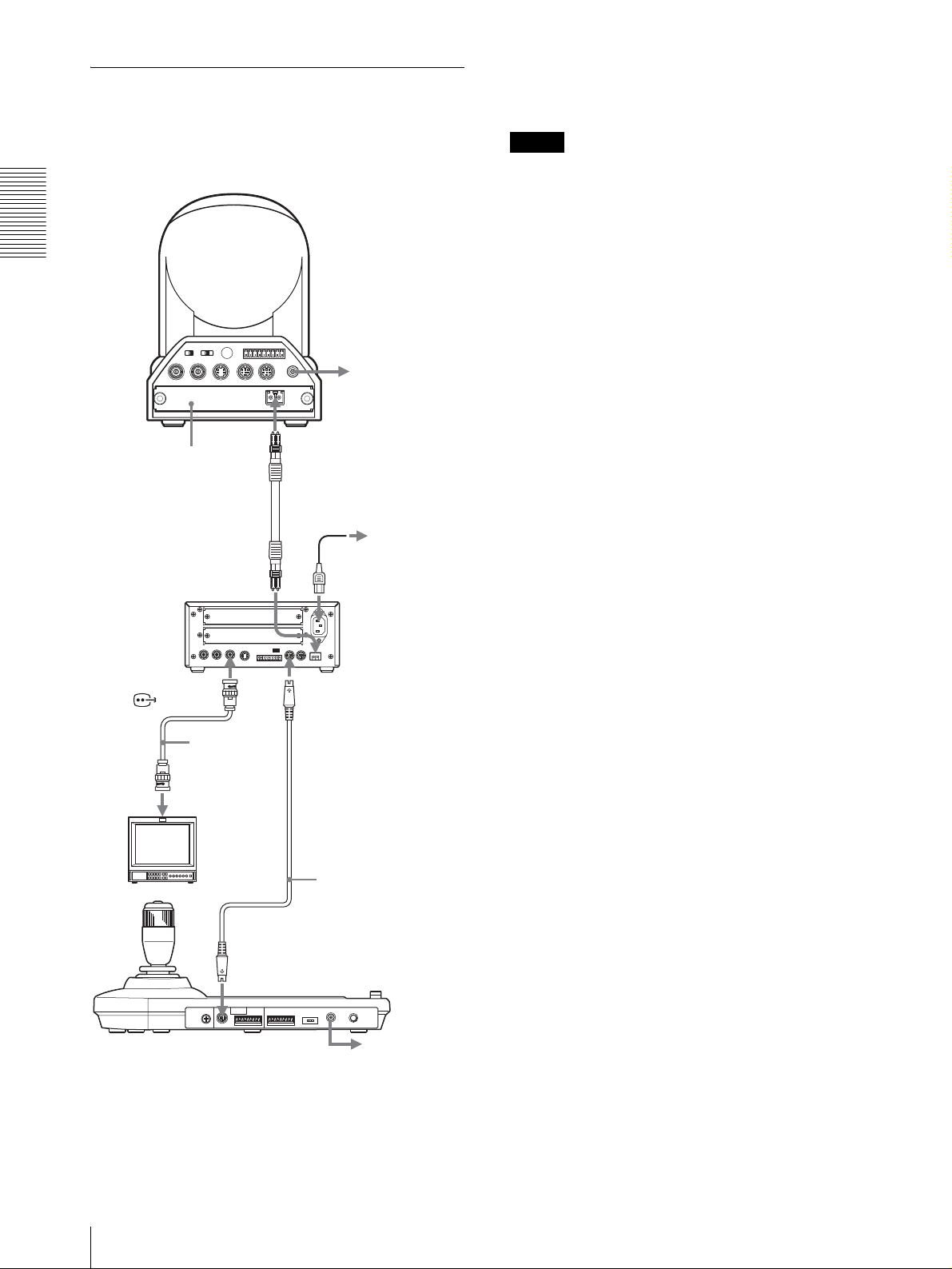
Connecting the BRU-300/300P
Optical Multiplex Unit
camera with this unit. For details of the connection,
refer to the Operating Instructions supplied with the
BRC-H700/H700P.
You can control the camera using this unit via the BRU300/300P Optical Multiplex Unit (not supplied).
Notes
When using the VISCA RS-232C connectors or VISCA
RS-422 connectors, check the VISCA FUNCTION
switch on the rear of the Optical Multiplex Unit and the
Camera BRC-300/300P
DIP switch on the bottom of this unit (page 8) are set to
RS-232C or RS-422 correctly.
Connections and Operations
R
1 2 3 4 5 6 7 8 9
1 2 3
OFF ON
IR SELECT
75
EXT SYNC IN
VIDEO S VIDEO
BRBK-303 Optical
Multiplex Card
VISCA RS-422
IN VISCA RS-232C OUT
CAMERA
!
DC IN
12V
to AC outlet
CCFC-M100 Optical
Fiber Cable
to AC outlet
AC power cord
(supplied with the
BRU-300/300P)
BRU-300/300P
Optical Multiplex
Unit
T VIDEO
(or S VIDEO)
VISCA RS-232C IN
75-ohm coaxial
cable (or Svideo cable)
RS-232C cable
Video monitor, etc.
(supplied)*
(SONY: 1-590-879-3X)
VISCA RS-232C
to AC outlet
* The VISCA RS-422 connection is also available if you use the
VISCA RS-422 connectors.
GB
For the BRC-H700/H700P camera, you can use the
BRU-H700/H700P Optical Multiplex Unit to control the
12
Connections
Page 13
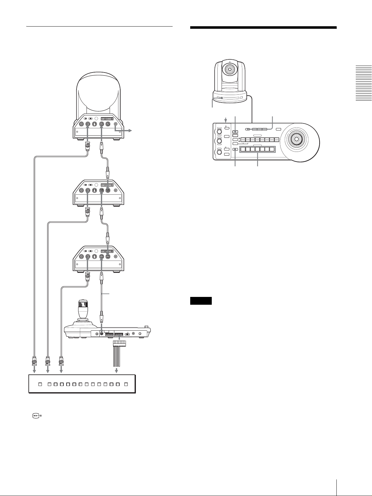
Connecting a Video Switcher
Use a commercially available contact-control type video
switcher to switch between the multiple camera signals
to be output.
Camera
Third to Seventh
camera
T VIDEO
Second camera
T VIDEO
75-ohm coaxial cable*
First camera
75-ohm coaxial cable*
to composite video input
75-ohm coaxial cable*
EXT SYNC IN
EXT SYNC IN
EXT SYNC IN
OFF ON
OFF ON
OFF ON
75
75
75
R
1 2 3 4 5 6 7 8 9
1 2 3
IR SELECT
VISCA RS-422
IN VISCA RS-232C OUT
VIDEO S VIDEO
VISCA RS-232C IN
R
1 2 3 4 5 6 7 8 9
1 2 3
IR SELECT
VISCA RS-422
IN VISCA RS-232C OUT
VIDEO S VIDEO
VISCA RS-232C IN
R
1 2 3 4 5 6 7 8 9
1 2 3
IR SELECT
VISCA RS-422
IN VISCA RS-232C OUT
VIDEO S VIDEO
VISCA RS-232C IN
MODE
RS-232C
VISCA
BRC-300/300P
!
DC IN
12V
to AC outlet
RS-232C cable
VISCA RS-232C OUT
!
DC IN
12V
RS-232C cable
VISCA RS-232C OUT
!
DC IN
12V
RS-232C cable (supplied)
(SONY: 1-590-879-3X)
VISCA RS-232C
CONTACT(TALLY)
RS-422 ON/OFF
TALLY/CONTACT
!
1919
TALLY
CONTACT DC IN 12V
TALLY/CONTACT
Turning on the Power
PANEL LIGHT
PANEL
BLACK
PAN-TILT
LIGHT
LIGHT
RESET
POSITION
2
3114
1
9
10
12
STD REV
CAMERA
1
234567
ONE PUSH
AWB
5136147158
MENU
16
– +
– +
NEAR FAR
RESET
VALUE
LOCK
RESET
R
PRESET
MODE
BRIGHT
SHIFT
L/R
DIRECTION
B
AUTO
FOCUS
AUTO
POWER
MANUAL
ONE PUSH
AF
1 2
POWER CAMERA
1
Connect the camera to an AC outlet.
The power of the camera is turned on and the
POWER lamp lights.
The camera will automatically pan and tilt and be
reset to the position stored in POSITION 1 (Pan/tilt
reset action).
2
Press the ON/OFF switch on this unit to turn it on.
The CAMERA button representing the camera
whose power was turned off last lights. (CAMERA
1 button lights by default.)
3
Turn on the peripheral devices.
Notes
• Be sure to turn on the power of the camera before the
power of this unit. Otherwise, the unit cannot
recognize the connected camera.
• Do not touch the joystick when turning on the power
of the unit. Doing so may affect the confirmation of
the origin.
Connections and Operations
to contact control
terminal
Video switcher (commercially available)
* You can also use an S-video connecting cable to connect the
S VIDEO connector on the camera and the S-video input
connector on the video switcher.
For connection with a video switcher, refer to the
Operating Instructions of the switcher.
To turn on/off the camera using this unit
As long as the camera is connected to an AC outlet, you
can turn the camera on or off with the POWER button on
this unit.
While holding down the POWER button, press the
CAMERA button corresponding to the camera whose
power you want to turn on/off.
When you turn the power off using this unit, the
POWER lamp turns off and the STANDBY lamp lights
on the camera.
Turning on the Power
13
GB
Page 14
Storing the Camera
Settings in Memory
The settings are stored in the memory of the
camera.
The pressed button flashes during storing. Flashing
stops when storing is completed.
– Presetting Feature
To recall the stored settings
Select the function of the POSITION 1 to 8 buttons by
Up to sixteen combinations of settings (sixteen
positions), including camera position, zooming,
Connections and Operations
focusing, and backlighting, can be stored in the memory
of the camera using this unit.
pressing the SHIFT button for more than one second, if
necessary. Press any of the POSITION buttons, 1 to 8,
in which you have stored the settings.
To cancel the preset memory
RESET
VALUE
LOCK
– +
R
MODE
BRIGHT
– +
B
AUTO
FOCUS
AUTO
MANUAL
ONE PUSH
AF
NEAR FAR
1
Press the PAN-TILT RESET button to reset the pan/
tilt position.
2
Press the CAMERA button to select the camera
whose settings you want to preset.
3
Adjust the position, zooming, focusing and
backlighting of the camera.
4
Press the SHIFT button for more than one second to
select the function of POSITION 1 to 8 buttons, if
necessary. (except the BRC-H700/H700P)
To store in positions 1 to 8, press the SHIFT button
so that the upper indicator lights. The POSITION
1 to 8 buttons can be used for positions 1 to 8.
To store in positions 9 to 16, press the SHIFT button
so that the lower indicator lights. The POSITION 1
to 8 buttons can be used for positions 9 to 16.
RESET
PRESET
1
SHIFT
9
STD REV
L/R
DIRECTION
POWER
1
51
PANEL
BLACK
PAN-TILT
ONE PUSH
LIGHT
LIGHT
RESET
AWB
POSITION
2
3114
5136147158
10
12
CAMERA
234567
24
Select the function of the POSITION 1 to 8 buttons
using the SHIFT button, if necessary. While holding
MENU
16
down the RESET button, press the POSITION button
from which you want to cancel the settings.
While holding down
RESET
PRESET
192103114125136147158
Press a POSITION button.
16
The pressed button flashes during canceling of the
settings. Flashing stops when the settings have been
canceled.
Notes
• When the power is turned on, the camera starts with
the settings stored in POSITION 1.
• If you want to retain the previous pan and tilt positions
when the power is turned off and turned on again, store
those positions in POSITION 1.
• When you are storing or canceling the settings in one
POSITION, you cannot call up, store or cancel the
settings in another POSITION.
To select positions 9 to 16 for the BRCH700/H700P
SHIFT
for positions 9 to 16
for positions 1 to 8
5
While holding down the PRESET button, press any
of the POSITION buttons, 1 to 8, in which you want
to store the settings. (except the BRC-H700/
H700P)
Press a POSITION button.
RESET
PRESET
192103114125136147158
16
While holding down the SHIFT button, press the
PRESET button (to store or recall the settings) or the
RESET button (when canceling the settings). The lower
indicator will light and the POSITION 1 to 8 buttons can
be used for positions 9 to 16.
When you release the SHIFT button, the upper indicator
lights and the POSITION 1 to 8 buttons can be used for
positions 1 to 8.
For the BRC-H700/H700P, you need not press the
SHIFT button for more than one second to switch the
indicator in advance.
GB
While holding down
14
Storing the Camera Settings in Memory – Presetting Feature
Page 15

Setting the Speed of the Camera
Moving to a Preset Position (BRC300/300P and BRC-H700/H700P
only)
You can select the panning/tilting speed when the
camera moves to a preset position.
1
Press the CAMERA button to select the camera
whose speed you want to set.
2
Press the POSITION button for which you want to
set the speed for more than one second.
All the CAMERA buttons, 1 to 7, flash.
3
Press one of the CAMERA buttons to select the
speed.
CAMERA button Panning/tilting speed
1 1 degree/sec.
2 2.2 degrees/sec.
3 4.8 degrees/sec.
4 11 degrees/sec.
5 23.3 degrees/sec.
6 43 degrees/sec.
7 60 degrees/sec. (default)
Connections and Operations
Now the camera will move to the position preset to
the pressed POSITION button with the selected
speed.
To set the speed of the camera moving to
a preset position for the BRC-H700/
H700P
To set the speed of the camera moving to a preset
position between 9 and 16, hold down the SHIFT button
and press the corresponding POSITION button.
Storing the Camera Settings in Memory – Presetting Feature
15
GB
Page 16

Appendix
Troubleshooting
Before bringing in your unit for service, check the
following as a guide to troubleshoot the problem. If the
problem cannot be corrected, consult with your Sony
dealer.
Symptom Cause Remedy
The power of the unit is not turned on. The AC power adaptor is not connected to the
Appendix
The camera cannot be operated with the
unit.
The unit cannot be operated at all.
DC IN 12V jack firmly.
The AC power cord is not inserted firmly into
the AC power adaptor or the AC outlet.
The connection using the VISCA RS-422
connectors is not correctly made.
VISCA control setting is not correct. Select the proper setting (RS-232C or RS-
The communication baud rate setting of the
camera and the unit differ.
—
Insert the power cord firmly as far as it will
go.
Insert the power cord firmly as far as it will
go.
Check that the connection to the VISCA RS422 connectors is correctly made, and the RS422 cable is properly connected.
422) with the DIP switch on the unit (page 8).
Select the communication baud rate, 9,600
bps or 38,400 bps, with the DIP switch on the
unit (page 8) which is selected on the camera.
Pull out the plug of the power cord from the
AC outlet, then reinsert it into the AC outlet
after a while.
GB
16
Troubleshooting
Page 17
Specifications
Input/output connectors
Control input/output
VISCA RS-232C OUT: Mini DIN 8-
pin type
VISCA RS-422: 9-pin type
TALLY IN/CONTACT OUT: 9-pin
type
Control signal format
9600 bps/38400 bps
Data: 8 bit
Stop bit: 1
Power connector
JEITA type4 (DC IN 12V)
General
Input voltage 12 V DC (10.8 to 13.2 V DC)
Current consumption
0.2 A max. (at 12 V DC), 2.4W
Operating temperature
0ºC to +40ºC (32ºF to 104ºF)
Storage temperature
-20ºC to +60ºC (-4ºF to 140ºF)
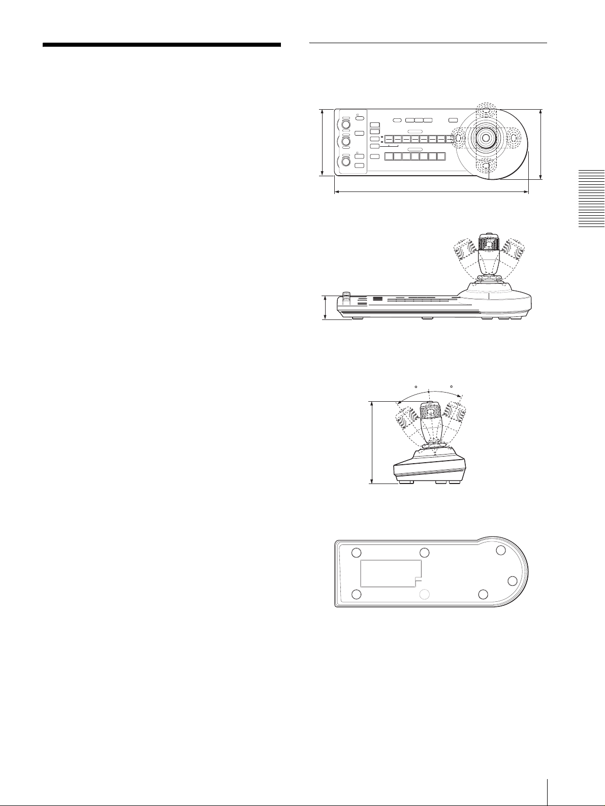
Dimensions 391.3 × 185 × 145.9 mm (w/h/d)
Mass Approx. 950 g (2 lb 15 oz)
1
/2 × 7 3/8 × 5 3/4 inches)
(15
Dimensions
Top
VALUE
– +
BRIGHT
– +
FOCUS
NEAR FAR
LOCK
RESET
R
PRESET
MODE
SHIFT
L/R
DIRECTION
B
AUTO
AUTO
POWER
MANUAL
ONE PUSH
AF
)
2
/
1
(5
137.2
Front
)
16
/
13
(1
45.9
Side
PANEL
BLACK
PAN-TILT
LIGHT
LIGHT
RESET
POSITION
2
3114
1
9
10
12
STD REV
CAMERA
1
234567
391.3 (15 1/2)
30
ONE PUSH
AWB
5136147158
30
MENU
16
)
4
/
3
(5
145.9
Appendix
Supplied accessories
MPA-AC1 AC power adaptor (Sony) (1)
AC power cord (1)
RS-232C connecting cable (1)
RS-422 connector plug (2)
Operating Instructions (1)
Design and specifications are subject to change without
notice.
Bottom
)
8
/
3
(7
185
Unit: mm (inches)
Specifications
17
GB
Page 18

Pin Assignments
VISCA RS-232C output connector (mini DIN 8pin, female)
TALLY/CONTACT connector (connector plug,
9-pin)
TALLY/CONTACT
RS-232C
Pin No. Function
1 CAMERA1
Pin No. Function
1 No Connection
2 No Connection
Appendix
3TXD IN
4 GND
5 RXD IN
6 GND
7 No Connection
8 No Connection
2 CAMERA2
3 CAMERA3
4 CAMERA4
5 CAMERA5
6 CAMERA6
7 CAMERA7
8 GND
9 GND
19
VISCA RS-422 connector (connector plug,
9-pin)
VISCA
RS-422
19
Pin No. Function
1 No Connection
2 No Connection
3 No Connection
4 No Connection
5 GND
6 RXD IN-
7 RXD IN+
8TXD IN-
9TXD IN+
GB
18
Specifications
Page 19
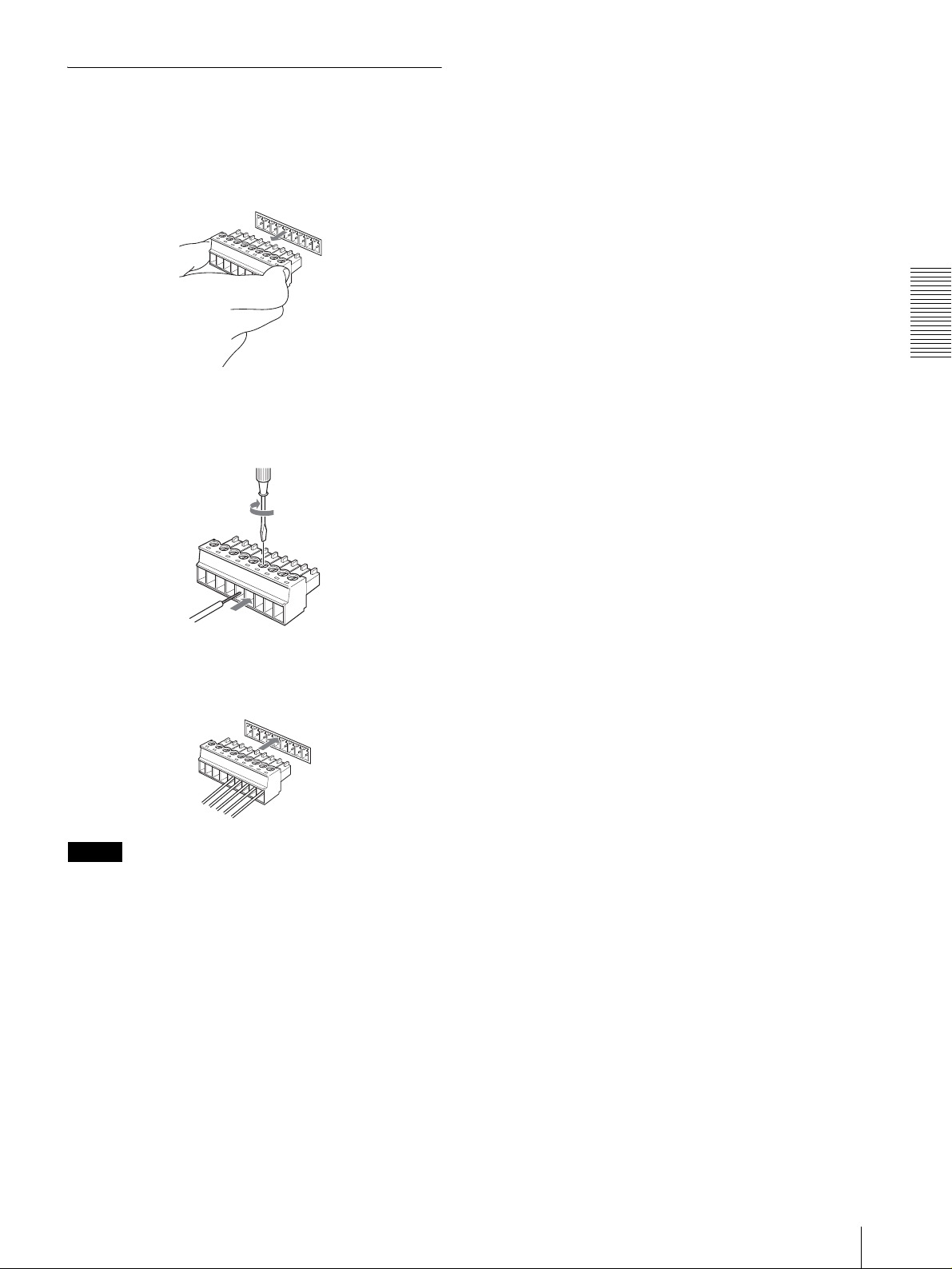
Using the VISCA RS-422 Connector
Plug
1
Grasp both ends of the VISCA RS-422 connector
plug and pull it out as shown in the illustration.
1
9
2
Insert a wire (AWG Nos. 28 to 18) into the desired
wire opening on the plug, and tighten the screw for
that wire using a flat-head screwdriver.
Flat-head screwdriver
Appendix
Wire
3
Insert the VISCA RS-422 connector plug into the
VISCA RS-422 connector.
1
9
Notes
• In order to stabilize the voltage level of the signal,
connect both ends to GND.
• When the connections using the VISCA RS-422
connectors are made, the VISCA RS-232C connection
is not available.
• The maximum connection distance with the VISCA
RS-422 connection is approximately 1,200 m (3,937
feet).
Specifications
19
GB
Page 20

AVERTISSEMENT
Afin de réduire les risques d’incendie ou
d’électrocution, ne pas exposer cet
appareil à la pluie ou à l’humidité.
Pour prévenir tout risque d’électrocution,
n’ouvrez pas le boîtier. Confiez l’entretien
de cet appareil exclusivement à un
personnel qualifié.
AVERTISSEMENT
Utilisez l’adaptateur secteur Sony MPA-AC1 fourni
avec cet équipement comme source d’alimentation.
Toute autre source d’alimentation pourrait être
dangereuse en faisant notamment courir un risque
d’incendie.
Le dispositif de déconnexion de cet équipement est la
fiche secteur de l’adaptateur secteur.
Vous devez utiliser la fiche secteur de cet équipement
pour le déconnecter du secteur.
Veillez à ce que la prise de courant se trouve près de
l’équipement et qu’elle soit facilement accessible.
En cas de fonctionnement anormal, débranchez la fiche
secteur.
IMPORTANT
La plaquette signalétique se trouve au-dessous de
l’appareil.
ATTENTION
Des champs électromagnétiques à des fréquences
spécifiques peuvent avoir une incidence sur l’image de
cet appareil.
FR
2
Page 21

Table des matières
Description générale
Caractéristiques ..................................................... 4
Précautions ............................................................. 4
Emplacement et fonction des pièces ..................... 5
Fonctions disponibles pour les caméras
Sony VISCA ..................................................... 8
Raccordements et opérations
Raccordements ....................................................... 9
Raccordement d’une caméra dotée d’un
connecteur VISCA RS-232C ........................... 9
Raccordement d’une caméra dotée d’un
connecteur VISCA RS-422 ............................ 10
Raccordement de plusieurs caméras dotées d’un
connecteur VISCA RS-232C ......................... 10
Raccordement de plusieurs caméras dotées d’un
connecteur VISCA RS-422 ............................ 11
Raccordement du module multiplex optique
BRU-300/300P ...............................................12
Raccordement d’un sélecteur vidéo ................. 13
Mise sous tension .................................................13
Mémorisation des paramètres de la caméra
– Fonction de mémorisation ............................... 14
Mémorisation de la vitesse de déplacement de la
caméra sur une position prédéfinie (BRC-300/
300P et BRC-H700/H700P seulement) ..........15
FR
Annexe
Dépannage ............................................................ 16
Spécifications ........................................................17
Dimensions ....................................................... 17
Brochage ........................................................... 18
Utilisation de la fiche de connexion
VISCA RS-422 ...............................................19
Table des matières
FR
3
Page 22

Description générale
Précautions
Description générale
Caractéristiques
La manette de commande à trois axes optique
permet de commander confortablement des
opérations de panoramique/inclinaison/zoom.
Commande facile de divers réglages de la caméra
Les touches du pupitre vous permettent de commander
facilement divers réglages de la caméra tels que mise au
point automatique, réglage de la mise au point
automatique One Push, réglage automatique de la
balance des blancs One Push et compensation de contrejour.
Les interfaces de communication VISCA RS232C/RS-422 permettent des communications
longue distance à haute vitesse.
Le pupitre permet de commander jusqu’à sept caméras
connectées en guirlande.
Une borne d’entrée de témoin de signalisation/
sortie de contact (fiche de connexion à
9 broches) permet le raccordement d’un
sélecteur vidéo.
Fonction de mémorisation pour la sauvegarde
des paramètres de la caméra
Le pupitre vous permet de sauvegarder jusqu’à 16
combinaisons* de paramètres de la caméra comme
positions de panoramique/inclinaison/zoom et d’autres
valeurs de réglage de la caméra dans la mémoire de la
caméra.
* Le nombre de positions pouvant être sauvegardées
dépend de la caméra connectée. (Pour la caméra vidéo
couleur 3CCD BRC-300/300P, 6 positions peuvent
être sauvegardées.)
Lieu d’utilisation ou de rangement
L’utilisation ou le rangement du pupitre dans les
endroits suivants peut l’endommager :
• endroits extrêmement chauds ou froids (température
de fonctionnement : 0 à +40
• endroits longuement exposés aux rayons directs du
soleil ou proximité d’une source de chaleur (appareil
de chauffage, par exemple)
• proximité d’une source de magnétisme puissant
• endroits proches de sources de rayonnement
électromagnétique puissant (émetteurs de radio ou de
télévision, par exemple)
• endroits soumis à de fortes vibrations ou chocs
°C [32 à 104 °F])
Aération
Pour prévenir toute surchauffe interne, n’entravez pas la
circulation d’air autour du pupitre.
Tran sport
Pour transporter le pupitre, remballez-le dans son
conditionnement d’origine ou dans des matériaux de
qualité équivalente.
Nettoyage
• Utilisez un chiffon doux et sec pour nettoyer
l’extérieur du pupitre. Éliminez les taches tenaces
avec un chiffon doux légèrement imprégné d’une
solution détergente, puis essuyez.
• N’utilisez pas de solvants volatils tels qu’alcool,
benzène ou diluants car ils peuvent attaquer le fini du
pupitre.
Caméras Sony VISCA pouvant être
commandées
Le pupitre peut commander les caméras suivantes :
• BRC-300/300P 3CCD Color Video Camera
• BRC-H700/H700P HD 3CCD Color Video Camera
• EVI-D100/D100P Color Video Camera
• EVI-D70/D70P Color Video Camera
• EVI-D30/D30P Color Video Camera
• SNC-RZ30N/RZ30P Network Camera
Remarques
• Les fonctions utilisables se limitent à celles dont est
dotée la caméra.
• Ce manuel décrit principalement les fonctions du
pupitre pour la caméra BRC-300/300P.
Lorsqu’une autre caméra est connectée, consultez son
mode d’emploi pour la description des fonctions
disponibles.
FR
4
Caractéristiques / Précautions
Page 23
Emplacement et
qhqjqkq
w
fonction des pièces
Ce manuel décrit les opérations du RM-BR300 lorsqu’il
est utilisé avec la caméra BRC-300/300P ou BRCH700/H700P.
Face avant
90qaqsqd qf qg
8
1
VALUE
– +
BRIGHT
– +
NEAR FAR
LOCK
R
MODE
B
AUTO
FOCUS
AUTO
MANUAL
ONE PUSH
AF
2
3
4
5
6
7
A Touche et témoin LOCK
Appuyez sur la touche LOCK pendant plus d’une
seconde. Le témoin LOCK s’allume et les valeurs
spécifiées avec les boutons VALUE/R, BRIGHT/B
et FOCUS sont verrouillées. (Les témoins des
boutons verrouillés sont éteints.)
La touche AUTO/MANUAL est également
désactivée.
Appuyez à nouveau sur la touche LOCK pendant
plus d’une seconde pour déverrouiller les boutons
et touches.
B Bouton VALUE/R
Lorsque vous avez sélectionné le mode de
réglage de la luminosité avec la touche MODE
(avec le témoin VALUE allumé) :
Ce bouton permet de régler la valeur du paramètre
(SHUTTER ou IRIS) sélectionné sur la caméra.
Lorsque le témoin VALUE est allumé, la fonction
du bouton diffère selon le mode d’exposition
sélectionné sur la caméra. Pour plus
d’informations, voir « Fonctions des boutons
VALUE et BRIGHT » à la page 5.
Lorsque vous avez sélectionné le mode de
réglage de la balance des blancs avec la touche
MODE (avec le témoin R allumé) :
Ce bouton permet de régler R. GAIN (gain du
rouge) (sauf pour l’EVI-D30/D30P).
Lorsque la caméra BRC-H700/H700P est
connectée, la fonction du bouton avec le témoin R
allumé diffère selon le mode de la balance des
blancs sélectionné sur la caméra. Pour plus
d’informations, voir « Fonctions des boutons R et B
pour la caméra BRC-H700/H700P » à la page 5.
PRESET
DIRECTION
POWER
RESET
1
SHIFT
9
STD REV
L/R
1
PANEL
BLACK
PAN-TILT
ONE PUSH
LIGHT
LIGHT
RESET
AWB
POSITION
2
3114
5136147158
12
10
CAMERA
234567
l
MENU
16
;
C Bouton BRIGHT/B
Lorsque vous avez sélectionné le mode de
réglage de luminosité avec la touche MODE
(avec le témoin BRIGHT allumé) :
Ce bouton permet de régler la valeur de luminosité
de la caméra, etc.
Lorsque le témoin BRIGHT est allumé, la fonction
du bouton diffère selon le mode d’exposition
sélectionné sur la caméra. Pour plus
d’informations, voir « Fonctions des boutons
VALUE et BRIGHT » à la page 5.
Lorsque vous avez sélectionné le mode de
réglage de la balance des blancs avec la touche
MODE (avec le témoin B allumé) :
Ce bouton permet de régler B. GAIN (gain du bleu)
(sauf pour l’EVI-D30/D30P).
Lorsque la caméra BRC-H700/H700P est
connectée, la fonction du bouton avec le témoin B
allumé diffère selon le mode de la balance des
blancs sélectionné sur la caméra. Pour plus
d’informations, voir « Fonctions des boutons R et B
pour la caméra BRC-H700/H700P » à la page 5.
Fonctions des boutons VALUE et BRIGHT
Selon le paramètre de mode d’exposition sélectionnée
sur la caméra, les fonctions du bouton VALUE et du
bouton BRIGHT changent comme suit :
Mode
d’exposition sur
Fonction du
bouton VALUE
la caméra
FULL AUTO Non utilisé Commande de
SHUTTER Pri Commande de
vitesse d’obturation
IRIS Pri Commande de
diaphragme
BRIGHT Non utilisé Commande de
MANUAL Commande de
vitesse d’obturation
GAIN Pri***
Réglage du gain***
* Lorsque la fonction de compensation d’exposition est
activée sur la caméra.
** La commande de diaphragme + gain est possible pour la
caméra BRC-H700/H700P.
*** Disponible pour la caméra BRC-H700/H700P seulement
Fonction du
bouton BRIGHT
niveau de
compensation
d’exposition*
Commande de
niveau de
compensation
d’exposition*
Commande de
niveau de
compensation
d’exposition*
niveau de
luminosité
Commande de
diaphragme**
Non utilisé
Fonctions des boutons R et B pour la caméra
BRC-H700/H700P
Lorsque vous avez sélectionné le mode de réglage de la
balance des blancs avec la touche MODE, les fonctions
du bouton R et du bouton B changent selon le mode de
balance des blancs sélectionné sur la caméra BRCH700/H700P.
Description générale
FR
Emplacement et fonction des pièces
5
Page 24

Description générale
Mode de
balance des
blancs sur la
caméra
MANUAL Commande de gain
AUTO, ONE
PUSH
Fonction du
bouton R
du rouge
Commande WB
SHIFT du rouge
Fonction du
bouton B
Commande de gain
du bleu
Commande WB
SHIFT du bleu
D Touc he M ODE
Appuyez sur cette touche pour sélectionner la
fonction du bouton VALUE/R et du bouton
BRIGHT/B.
Lorsque le mode de réglage de la luminosité est
sélectionné, les témoins VALUE et BRIGHT sont
allumés.
Lorsque le mode de réglage de la balance des
blancs est sélectionné, les témoins R et B sont
allumés.
E Bouton FOCUS
Ce bouton est activé lorsque vous sélectionnez
MANUAL avec la touche AUTO/MANUAL.
Tournez le bouton dans le sens inverse des aiguilles
d’une montre (vers NEAR) pour effectuer la mise
au point sur un sujet proche et dans le sens des
aiguilles d’une montre (vers FAR) pour effectuer la
mise au point sur un sujet éloigné.
F Touche AUTO/MANUAL et témoin AUTO
Appuyez sur cette touche pour sélectionner le mode
de mise au point AUTO ou MANUAL.
Lorsque AUTO est sélectionné, le témoin AUTO
s’allume et la caméra effectue automatiquement la
mise au point sur le sujet au centre de l’écran. Le
bouton FOCUS et la touche ONE PUSH AF sont
désactivés.
Lorsque MANUAL est sélectionné, le bouton
FOCUS et la touche ONE PUSH AF sont activés
(avec le témoin FOCUS allumé).
G Touche ONE PUSH AF
Cette touche est activée lorsque vous sélectionnez
MANUAL avec la touche AUTO/MANUAL.
Appuyez sur la touche pour exécuter une mise au
point automatique One Push (sauf pour l’EVI-D30/
D30P).
H Touche RESET
Tout en maintenant cette touche enfoncée, appuyez
sur l’une des touches POSITION. La mémoire de la
caméra correspondant à la touche POSITION
enfoncée est réinitialisée aux conditions prédéfinies
en usine.
Lorsque plusieurs caméras sont connectées, vous
pouvez spécifier les adresses de caméra en
maintenant cette touche enfoncée et en appuyant
sur la touche POWER.
I Touche PRESET
Tout en maintenant cette touche enfoncée, appuyez
sur l’une des touches POSITION. Les réglages
actuels de la caméra sont mémorisés dans la caméra
correspondant à la touche POSITION enfoncée.
J Touche PANEL LIGHT
Appuyez sur cette touche pour éclairer toutes les
touches POSITION et les touches CAMERA.
Appuyez à nouveau sur cette touche pour éteindre
l’éclairage.
K Touche BACK LIGHT
Lorsque le mode d’exposition FULL AUTO est
sélectionné sur la caméra, appuyez sur cette touche
pour activer la fonction de compensation de contrejour de la caméra. Appuyez à nouveau sur cette
touche pour désactiver la fonction.
Pour la caméra BRC-H700/H700P, appuyez sur
cette touche tout en maintenant la touche SHIFT
enfoncée pour activer la fonction de compensation
de spots lumineux de la caméra. Cette fonction
règle l’exposition à un niveau plus sombre si une
partie du sujet filmé est éclairée. Pour désactiver la
fonction de compensation de spots lumineux,
appuyez à nouveau sur cette touche tout en
maintenant la touche SHIFT enfoncée.
L Touche PAN-TILT RESET
Appuyez sur cette touche pour ramener la position
de panoramique/inclinaison de la caméra aux
conditions initiales.
M Touche ONE PUSH AWB
Lorsque le mode de balance des blancs ONE PUSH
est sélectionné sur la caméra, appuyez sur cette
touche pour effectuer un réglage One Push de la
balance des blancs.
N Touc he M ENU
Pour la caméra BRC-300/300P ou BRC-H700/
H700P, appuyez sur cette touche pendant environ
une seconde pour afficher le menu de la caméra,
pour revenir au menu principal ou pour faire
disparaître le menu.
Pour les autres caméras, appuyez sur cette touche
pendant environ une seconde pour activer/
désactiver l’affichage des données à l’écran.
O Manette de commande
La manette de commande permet d’effectuer des
opérations de panoramique/inclinaison et de zoom.
Sélectionnez la caméra que vous désirez
commander à l’aide des touches CAMERA et
actionnez la manette de commande.
Panoramique et inclinaison
Lorsque vous inclinez la manette de commande
vers la droite ou la gauche, la caméra effectue un
FR
6
Emplacement et fonction des pièces
Page 25
panoramique. Lorsque vous l’inclinez vers l’avant
ou l’arrière, la caméra s’incline.
La vitesse de panoramique/inclinaison change en
fonction de l’angle d’inclinaison.
Lorsque vous relâchez la manette de commande, le
mouvement de la caméra s’arrête.
Zoom
Lorsque vous tournez le cadran sur la partie
supérieure de la manette de commande dans le sens
des aiguilles d’une montre, le sujet devient plus
grand (zoom avant). Lorsque vous le tournez dans
le sens inverse des aiguilles d’une montre, le sujet
devient plus petit (zoom arrière).
Pour ramener la caméra vers l’avant
Lorsque vous appuyez sur la touche au-dessus de la
manette de commande pendant une ou deux
secondes, que le menu soit ou non affiché, les
positions de panoramique/inclinaison/zoom sont
ramenées à l’état initial et la caméra revient vers
l’avant.
P Touche et témoins SHIFT
Appuyez sur cette touche pendant plus d’une
seconde pour sélectionner la fonction des touches
POSITION pour les positions 1 à 8 ou les positions
9 à 16.
Le témoin supérieur s’allume pour les positions 1 à
8 et le témoin inférieur pour les positions 9 à 16.
Pour la caméra BRC-H700/H700P, appuyez sur
l’une des touches POSITION tout en maintenant la
touche SHIFT enfoncée. Le témoin inférieur
s’allume et vous pouvez utiliser les touches
POSITION pour les positions 9 à 16. Si vous
relâchez la touche SHIFT, le témoin supérieur
s’allume et vous pouvez utiliser les touches
POSITION pour les positions 1 à 8.
Q Touche L/R DIRECTION
La caméra est préréglée pour se tourner vers la
droite lorsque vous inclinez la manette de
commande vers la droite. Tout en maintenant cette
touche enfoncée, appuyez sur la touche POSITION
2 (REV) pour inverser la direction de panoramique
par rapport au sens vers lequel vous inclinez la
manette de commande. Pour ramener la direction à
l’état initial, appuyez sur la touche POSITION 1
(STD) tout en maintenant cette touche enfoncée.
Tout en maintenant cette touche enfoncée, appuyez
sur l’une des touches CAMERA 1 à 7 pour mettre
la caméra correspondant à la touche appuyée sous/
hors tension.
S Touches CAMERA
Appuyez sur l’une des ces touches pour
sélectionner une caméra parmi celles qui sont
connectées. La touche CAMERA sélectionnée
s’allume en bleu.
T Touches POSITION
Vous pouvez mémoriser divers paramètres de la
caméra tels que les positions de panoramique,
inclinaison et zoom dans la mémoire de la caméra
correspondant à chaque touche POSITION afin de
pouvoir les rappeler ultérieurement.
Fonctions des touches POSITION pour
les caméras EVI-D100/D100P et EVI-D70/
D70P
Lorsque la caméra EVI-D100/D100P ou EVI-D70/
D70P est connectée à ce pupitre, le pupitre détecte
automatiquement le modèle de la caméra, et les
fonctions des positions 7 à 16 des touches POSITION
changent comme indiqué dans le tableau ci-dessous.
Ceci vous permet de commander directement la caméra
sans la connecter à un ordinateur.
Touche
POSITION
Position 7 Exposition automatique – Mode Full Auto
Position 8 Exposition automatique – Mode Bright
Position 9 Zoom numérique – Activé
Position 10 Zoom numérique – Désactivé
Position 11 Mode de balance des blancs automatique
Position 12 Mode de balance des blancs manuelle
Position 13 Mode de balance des blancs One Push
Position 14 Mode ATW (balance des blancs à suivi
Position 15 IR Cut-Removable (ICR) – Activé
Position 16 IR Cut-Removable (ICR) – Désactivé
Pour plus d’informations sur chaque fonction, consultez
le Manuel Technique de la caméra.
Face arrière/inférieure
Fonction
automatique)
Description générale
R Touch e P OWER
Appuyez sur cette touche pour éclairer la ou les
touches CAMERA correspondant à l’état de la ou
des caméras connectées.
Bleu : L’alimentation de la caméra est établie.
Jaune vert : L’appareil est en mode de veille.
Éteint : Aucune caméra n’est connectée.
MODE
RS-232C
RS-422 ON/OFF
VISCA
1919
TALLY/CONTACT
CONTACT(TALLY)
TALLY
CONTACT DC IN 12V
!
ws wd wf wg wh wj wkwa
Emplacement et fonction des pièces
FR
7
Page 26

Description générale
U Sélecteur MODE
Sélectionnez la position correspondant à la caméra
compatible VISCA à connecter.
Position du
sélecteur
0 Automatiquement sélectionné (par
1 BRC-300/300P
2 EVI-D70/D70P
3 EVI-D100/D100P
4 EVI-D30/D30P
5SNC-RZ30N/RZ30P
6 BRC-H700/H700P
Remarques
Mode de caméra
défaut)
• Utilisez une position 1 à 4 lorsque toutes les
caméras connectées sont de même modèle.
• Utilisez la position 5 pour la SNC-RZ30N/
RZ30P.
V Connecteur VISCA RS-232C
Raccordez ce connecteur au connecteur VISCA
RS-232C IN de la caméra ou du module multiplex
optique.
W Connecteur VISCA RS-422
Raccordez ce connecteur au connecteur VISCA
RS-422 de la caméra ou du module multiplex
optique.
Une fiche de connexion RS-422 a été montée en
usine.
X Connecteur TALLY/CONTACT
Ce connecteur est utilisé pour l’entrée du signal du
témoin de signalisation ou la sortie du signal de
contact.
Sélectionnez la fonction du connecteur à l’aide du
sélecteur TALLY/CONTACT.
Une fiche de connexion RS-422 a été montée en
usine.
Y Sélecteur TALLY/CONTACT
Ce sélecteur permet de sélectionner la fonction du
connecteur TALLY/CONTACT.
TALLY : Le témoin de signalisation de la caméra
sélectionnée avec le sélecteur vidéo connecté
s’allume.
CONTACT : La sortie de contact correspondant à
l’adresse de la caméra sélectionnée avec ce pupitre
est court-circuitée contre le sélecteur vidéo
connecté.
CONTACT (TALLY) : La sortie de contact
correspondant à l’adresse de caméra sélectionnée
avec ce pupitre est court-circuitée contre le
sélecteur vidéo connecté et le témoin de
signalisation de la caméra sélectionnée avec le
sélecteur vidéo connecté s’allume.
wh Connecteur DC IN 12V
Permet de brancher l’adaptateur secteur fourni.
wj Commutateurs DIP (face inférieure)
Commutateur 1 (Sélecteur RS-232C/RS-422)
Placez-le sur ON pour RS-422 ou sur OFF pour RS232C.
Commutateur 2 (Sélecteur de vitesse de
transmission)
Placez-le sur ON pour 38 400 bit/s ou sur OFF pour
9 600 bit/s.
wk Interrupteur ON/OFF
Appuyez sur cet interrupteur pour mettre le pupitre
sous/hors tension.
Remarque
Positionnez les commutateurs avant de mettre ce pupitre
sous tension. Le changement de position ne serait
autrement pas pris en compte.
Fonctions disponibles pour les caméras Sony VISCA
Les fonctions des boutons, touches et connecteurs de la liste suivante diffèrent selon le modèle de caméra connecté. Les
fonctions des autres pièces sont les mêmes pour tous les modèles de caméra.
Pièces BRC-300/
300P, BRC-
H700/H700P
B Bouton VALUE/R a a a
C Bouton BRIGHT/B a a a
G Touche ONE PUSH AF a a a
L Touche PAN-TILT RESET a a a a
N Touche MENU a a a a
R Touche POWER a a a a
S Touches CAMERA a a a a
W Connecteur VISCA RS-422 a
a: disponible, ×: non disponible
FR
8
Emplacement et fonction des pièces
EVI-D100/
D100P
×
EVI-D70/
D70P
a
EVI-D30/
D30P
×
×
×
× ×
SNC-RZ30N/
RZ30P
a
a
a
×
×
×
×
Page 27

Raccordements et opérations
Remarque
Lorsque vous utilisez les connecteurs VISCA RS-232C,
assurez-vous que le commutateur DIP au-dessous de ce
pupitre (page 8) se trouve sur RS-232C.
Raccordements
Cette section présente des exemples de raccordement à
la caméra BRC-300/300P. Pour le raccordement à
d’autres caméras, consultez leur mode d’emploi.
Raccordement d’une caméra dotée
d’un connecteur VISCA RS-232C
1
Raccordez ce pupitre à la caméra à l’aide du câble
de raccordement RS-232C fourni avec le pupitre.
2
Branchez ce pupitre à une prise de courant à l’aide
de l’adaptateur secteur et du cordon d’alimentation
fournis.
Caméra BRC-300/300P
Câbles de raccordement
Utilisez le câble de raccordement suivant pour raccorder
les périphériques de cette chaîne.
Câble N° de pièce Nombre
Câble RS-232C
(3 m (10 pieds))
Câble RS-232C
1-590-879-3X 1
Raccordements et opérations
OFF ON
EXT SYNC IN
IR SELECT
75
VIDEO S VIDEO
1 2 3
R
1 2 3 4 5 6 7 8 9
VISCA RS-422
!
IN VISCA RS-232C OUT
DC IN
12V
VISCA RS-232C IN
Câble RS-232C (fourni)
(SONY : 1-590-879-3X)
VISCA RS-232C
DC IN 12V
Adaptateur secteur
MPA-AC1 (fourni)
vers prise de
courant
Cordon
d’alimentation
secteur
(fourni)
vers prise de
courant
Raccordements
FR
9
Page 28

Raccordement d’une caméra dotée
Raccordement de plusieurs
Raccordements et opérations
d’un connecteur VISCA RS-422
Vous pouvez utiliser les connecteurs VISCA RS-422 au
lieu des connecteurs VISCA RS-232C pour raccorder ce
pupitre à la caméra. L’utilisation des connecteurs
VISCA RS-422 permet un raccordement sur une
distance maximale de 1 200 m (3 937 pieds).
Préparez le câble de raccordement en utilisant les fiches
de connexion RS-422 fournies avec ce pupitre.
Pour la préparation du câble, reportez-vous au brochage
du connecteur VISCA RS-422 (page 18).
Pour l’utilisation des fiches de connexion RS-422, voir
page 19.
Caméra BRC-300/300P
vers prise de
courant
VISCA RS-422
caméras dotées d’un connecteur
VISCA RS-232C
Le raccordement avec des câbles VISCA RS-232C (type
croisé) permet de commander jusqu’à sept caméras avec
un seul pupitre de télécommande RM-BR300.
VISCA RS-232C
Caméra BRC300/300P
EXT SYNC IN
OFF ON
75
1 2 3
IR SELECT
VIDEO S VIDEO
R
1 2 3 4 5 6 7 8 9
IN VISCA RS-232C OUT
VISCA RS-422
Câble RS-232C (fourni)
(SONY : 1-590-879-3X)
vers VISCA RS-232C IN
!
DC IN
12V
vers prise de
courant
vers prise de
courant
Câble VISCA RS-422
VISCA RS-422
DC IN 12V
Cordon
d’alimentation
secteur
(fourni)
vers prise de
Adaptateur secteur
courant
MPA-AC1 (fourni)
Remarques
• Lorsque vous utilisez les connecteurs VISCA RS-422,
assurez-vous que le commutateur DIP au-dessous de
ce pupitre (page 8) se trouve sur RS-422.
• Lorsque les raccordements sont effectués à l’aide des
connecteurs VISCA RS-422, la connexion VISCA
RS-232C n’est pas disponible.
Première caméra
VISCA RS-232C OUT
Câble RS-232C
VISCA RS-232C IN
R
1 2 3 4 5 6 7 8 9
1 2 3
OFF ON
IR SELECT
75
EXT SYNC IN
VIDEO S VIDEO
Seconde caméra
VISCA RS-422
!
IN VISCA RS-232C OUT
DC IN
12V
VISCA RS-232C OUT
Câble RS-232C
VISCA RS-232C IN
R
1 2 3 4 5 6 7 8 9
1 2 3
OFF ON
IR SELECT
EXT SYNC IN
75
VIDEO S VIDEO
VISCA RS-422
IN VISCA RS-232C OUT
!
DC IN
12V
Troisième à septième caméras
vers prise de
courant
vers prise de
courant
FR
10
Raccordements
Page 29

Remarque
Remarques
Lorsque vous utilisez les connecteurs VISCA RS-232C,
assurez-vous que le commutateur DIP au-dessous de ce
pupitre (page 8) se trouve sur RS-232C.
Pour attribuer les adresses de caméra
Avant l’utilisation, vous devez attribuer des adresses aux
caméras connectées en procédant comme il est indiqué
ci-dessous. Vous pourrez alors sélectionner la caméra à
commander en appuyant simplement sur la touche
CAMERA correspondante.
1
Mettez toutes les caméras connectées et ce pupitre
sous tension.
2
Tout en maintenant la touche RESET enfoncée,
appuyez sur la touche POWER de ce pupitre.
Le pupitre reconnaît les caméras connectées et leur
attribue automatiquement des adresses de 1 à 7 dans
l’ordre de leur connexion.
3
Appuyez sur la touche POWER de ce pupitre et
assurez-vous que les touches CAMERA
s’allument.
Le nombre de touches CAMERA allumées indique
le nombre de caméras auxquelles une adresse a été
attribuée.
Vous pouvez maintenant sélectionner la caméra à
commander en appuyant sur la touche CAMERA.
• Lorsque vous utilisez les connecteurs VISCA RS-422,
assurez-vous que le commutateur DIP au-dessous de
ce pupitre (page 8) se trouve sur RS-422.
• Lorsque les raccordements sont effectués à l’aide des
connecteurs VISCA RS-422, la connexion VISCA
RS-232C n’est pas disponible.
vers prise
de courant
vers prise de
courant
Caméra BRC300/300P
EXT SYNC IN
OFF ON
75
1 2 3
IR SELECT
VIDEO S VIDEO
R
IN VISCA RS-232C OUT
1 2 3 4 5 6 7 8 9
VISCA RS-422
VISCA RS-422
Câble VISCA RS-422
vers VISCA RS-422
!
DC IN
12V
Raccordements et opérations
Raccordement de plusieurs
caméras dotées d’un connecteur
VISCA RS-422
Le raccordement via les connecteurs VISCA RS-422
permet de commander plusieurs caméras. Ceci permet
un raccordement sur une distance maximale de 1 200 m
(3 937 pieds).
Préparez le câble de raccordement en utilisant la fiche de
connexion RS-422 fournie avec ce pupitre.
Pour la préparation du câble, reportez-vous au brochage
du connecteur VISCA RS-422 (page 18).
Pour l’utilisation des fiches de connexion RS-422, voir
page 19.
Pour le schéma de câblage de la connexion VISCA RS422, consultez le mode d’emploi fourni avec la BRC300/300P.
Première caméra
1 2 3
OFF ON
IR SELECT
75
EXT SYNC IN
VIDEO S VIDEO
Seconde caméra
R
IN VISCA RS-232C OUT
1 2 3 4 5 6 7 8 9
VISCA RS-422
VISCA RS-422
!
DC IN
12V
VISCA RS-422
VISCA RS-422
R
1 2 3 4 5 6 7 8 9
1 2 3
OFF ON
IR SELECT
EXT SYNC IN
75
VIDEO S VIDEO
VISCA RS-422
IN VISCA RS-232C OUT
!
DC IN
12V
Troisième à septième caméras
Câble VISCA RS-422
VISCA RS-422
vers prise de
courant
Câble VISCA RS-422
vers prise de
courant
Raccordements
11
FR
Page 30

Raccordements et opérations
Raccordement du module multiplex
optique BRU-300/300P
Vous pouvez commander la caméra depuis ce pupitre via
le module multiplex optique BRU-300/300P (non
fourni).
Caméra BRC-300/300P
R
1 2 3 4 5 6 7 8 9
1 2 3
OFF ON
IR SELECT
EXT SYNC IN
75
VIDEO S VIDEO
VISCA RS-422
IN VISCA RS-232C OUT
!
DC IN
12V
vers prise de
courant
Pour la caméra BRC-H700/H700P, vous pouvez utiliser
le module multiplex optique BRU-H700/H700P pour
commander la caméra avec ce pupitre. Pour plus
d’informations sur le raccordement, consultez le mode
d’emploi de la BRC-H700/H700P.
Remarque
Lorsque vous utilisez les connecteurs VISCA RS-232C
ou VISCA RS-422, assurez vous que le commutateur
VISCA FUNCTION à l’arrière du module multiplex
optique et le commutateur DIP au-dessous de ce pupitre
(page 8) se trouvent respectivement sur RS-232C ou
RS-422.
Carte multiplex
optique BRBK-303
T VIDEO
(ou S VIDEO)
Câble coaxial de
75 ohms (ou
câble S-vidéo)
Moniteur vidéo, etc.
CAMERA
Câble à fibres optiques
CCFC-M100
vers prise
de courant
Cordon
d’alimentation
secteur (fourni avec
le BRU-300/300P)
Module multiplex
optique BRU-300/
300P
VISCA RS-232C IN
Câble RS-232C
(fourni)*
(SONY : 1-590-879-3X)
FR
VISCA RS-232C
vers prise de
courant
* La connexion VISCA RS-422 est également disponible si vous
utilisez les connecteurs VISCA RS-422.
12
Raccordements
Page 31

Raccordement d’un sélecteur vidéo
Utilisez un sélecteur vidéo à commande de contact en
vente dans le commerce pour sélectionner la sortie des
signaux de plusieurs caméras.
Mise sous tension
Troisième à
septième caméras
T VIDEO
Seconde caméra
T VIDEO
Câble coaxial de 75 ohms*
Première caméra
Câble coaxial de 75 ohms*
EXT SYNC IN
EXT SYNC IN
EXT SYNC IN
OFF ON
OFF ON
OFF ON
75
75
75
R
1 2 3 4 5 6 7 8 9
1 2 3
IR SELECT
VISCA RS-422
IN VISCA RS-232C OUT
VIDEO S VIDEO
VISCA RS-232C IN
R
1 2 3 4 5 6 7 8 9
1 2 3
IR SELECT
VISCA RS-422
IN VISCA RS-232C OUT
VIDEO S VIDEO
VISCA RS-232C IN
R
1 2 3 4 5 6 7 8 9
1 2 3
IR SELECT
VISCA RS-422
IN VISCA RS-232C OUT
VIDEO S VIDEO
VISCA RS-232C IN
Caméra
BRC-300/300P
!
DC IN
12V
vers prise de
courant
Câble RS-232C
VISCA RS-232C OUT
!
DC IN
12V
Câble RS-232C
VISCA RS-232C OUT
!
DC IN
12V
1 2
VALUE
– +
R
BRIGHT
– +
B
FOCUS
NEAR FAR
LOCK
MODE
AUTO
AUTO
MANUAL
ONE PUSH
AF
RESET
RESET
PRESET
SHIFT
L/R
DIRECTION
POWER
PANEL LIGHT
PANEL
BLACK
PAN-TILT
LIGHT
LIGHT
RESET
POSITION
2
3114
1
9
10
12
STD REV
CAMERA
1
234567
ONE PUSH
AWB
5136147158
MENU
16
POWER CAMERA
1
Branchez la caméra à une prise de courant.
La caméra est mise sous tension et le témoin
POWER s’allume.
Une opération de panoramique et inclinaison est
automatiquement exécutée pour ramener la caméra
sur la position mémorisée dans POSITION 1
(opération de retour sur la position initiale de
panoramique/inclinaison).
2
Appuyez sur l’interrupteur ON/OFF de ce pupitre
pour le mettre sous tension.
La touche CAMERA correspondant à la dernière
caméra mise hors tension s’allume. (La touche
CAMERA 1 s’allume par défaut.)
Raccordements et opérations
Câble RS-232C (fourni)
(SONY : 1-590-879-3X)
VISCA RS-232C
MODE
RS-232C
VISCA
1919
CONTACT(TALLY)
RS-422 ON/OFF
TALLY/CO NTA CT
!
TALLY
CONTACT DC IN 12V
TALLY/CONTACT
vers entrée vidéo composite
Câble coaxial de 75 ohms*
vers borne de
commande de contact
Sélecteur vidéo (en vente dans le commerce)
* Vous pouvez également utiliser un câble de raccordement S-
vidéo pour raccorder le connecteur S VIDEO de la caméra
au connecteur d’entrée S-vidéo du sélecteur vidéo.
Pour le raccordement à un sélecteur vidéo, consultez son
mode d’emploi.
3
Mettez les périphériques sous tension.
Remarques
• Mettez toujours la caméra sous tension avant ce
pupitre. À défaut, le pupitre ne reconnaîtrait pas la
caméra connectée.
• Ne touchez pas la manette de commande lorsque vous
mettez le pupitre sous tension. Ceci pourrait affecter le
repérage de l’origine.
Pour mettre la caméra sous/hors tension
à l’aide de ce pupitre
Tant que la caméra est branchée à une prise de courant,
vous pouvez la mettre sous tension et hors tension à
l’aide de la touche POWER de ce pupitre.
Tout en maintenant la touche POWER enfoncée,
appuyez sur la touche CAMERA correspondant à la
caméra que vous désirez mettre sous/hors tension.
Lorsque vous coupez l’alimentation à l’aide de ce
pupitre, le témoin POWER s’éteint et le témoin
STANDBY s’allume sur la caméra.
Mise sous tension
13
FR
Page 32
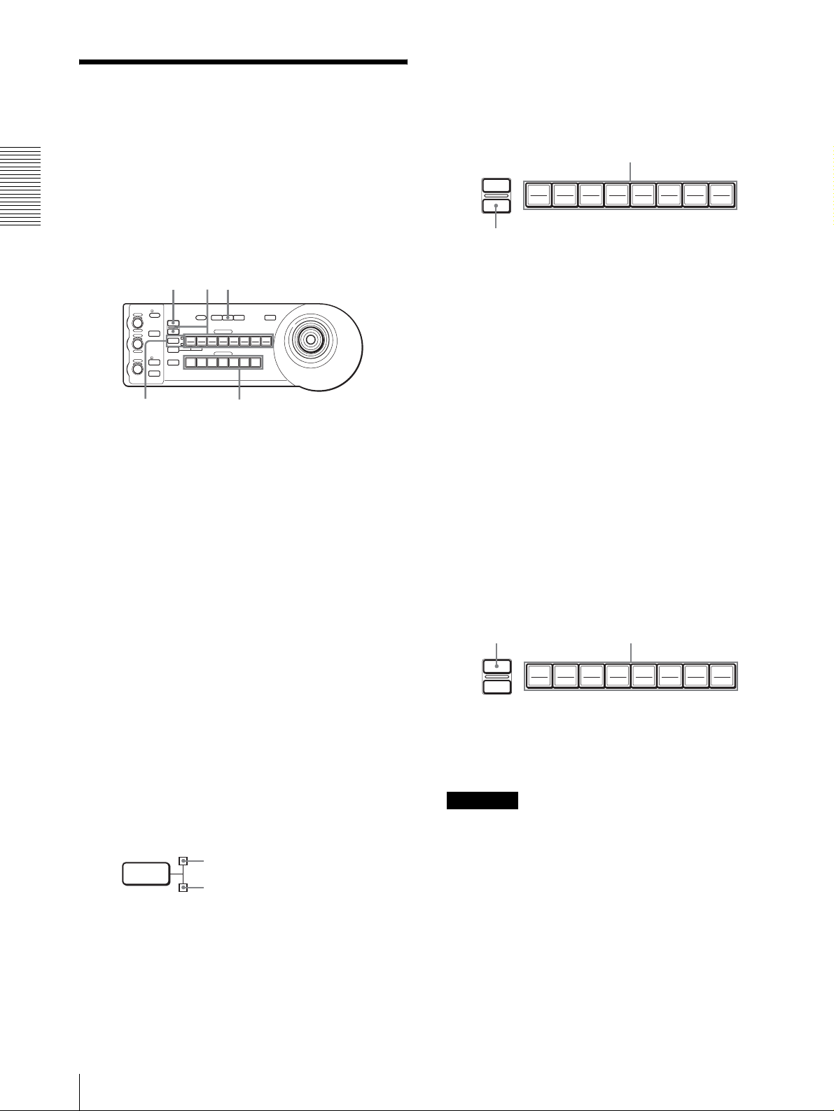
Mémorisation des
paramètres de la caméra
5
Tout en maintenant la touche PRESET enfoncée,
appuyez sur la touche POSITION 1 à 8 sur laquelle
vous désirez mémoriser les paramètres. (sauf pour
la BRC-H700/H700P)
Raccordements et opérations
– Fonction de mémorisation
Vous pouvez mémoriser jusqu’à seize combinaisons de
paramètres (seize positions), y compris position de la
caméra, zoom, mise au point et contre-jour, dans la
caméra à l’aide de ce pupitre.
RESET
VALUE
LOCK
– +
R
MODE
BRIGHT
– +
B
AUTO
FOCUS
AUTO
MANUAL
ONE PUSH
AF
NEAR FAR
1
Appuyez sur la touche PAN-TILT RESET pour
exécuter une opération de retour sur la position
initiale de panoramique/inclinaison.
2
Appuyez sur la touche CAMERA pour sélectionner
la caméra dont vous désirez mémoriser les
paramètres.
3
Réglez la position, le zoom, la mise au point et le
contre-jour de la caméra.
RESET
PRESET
1
SHIFT
9
STD REV
L/R
DIRECTION
POWER
1
51
PANEL
BLACK
PAN-TILT
ONE PUSH
LIGHT
LIGHT
RESET
AWB
POSITION
2
3114
5136147158
10
12
CAMERA
234567
24
MENU
16
Appuyez sur une touche POSITION.
RESET
PRESET
192103114125136147158
16
Tout en appuyant
Les paramètres sont mémorisés dans la caméra.
La touche enfoncée clignote pendant la
mémorisation. Le clignotement cesse lorsque la
mémorisation est terminée.
Pour rappeler les paramètres mémorisés
Sélectionnez la fonction des touches POSITION 1 à 8 en
appuyant sur la touche SHIFT pendant plus d’une
seconde si nécessaire. Appuyez sur la touche
POSITION 1 à 8 sur laquelle ont été mémorisés les
paramètres.
Effacement de la mémoire
Sélectionnez la fonction des touches POSITION 1 à 8 à
l’aide de la touche SHIFT si nécessaire. Tout en
maintenant la touche RESET enfoncée, appuyez sur la
touche POSITION de laquelle vous désirez effacer les
paramètres.
4
Appuyez sur la touche SHIFT pendant plus d’une
seconde pour sélectionner la fonction des touches
of POSITION 1 à 8 si nécessaire. (sauf pour la
BRC-H700/H700P)
Pour mémoriser sur les positions 1 à 8, appuyez sur
la touche SHIFT de façon que le témoin supérieur
s’allume. Les touches POSITION 1 à 8 peuvent être
utilisées pour les positions 1 à 8.
Pour mémoriser les positions 9 à 16, appuyez sur la
touche SHIFT de façon que le témoin inférieur
s’allume. Les touches POSITION 1 à 8 peuvent être
utilisées pour les positions 9 à 16.
SHIFT
pour les positions 1 à 8
pour les positions 9 à 16
Tout en appuyant
RESET
PRESET
192103114125136147158
Appuyez sur une touche POSITION.
16
La touche enfoncée clignote pendant l’effacement des
paramètres. Le clignotement cesse lorsque les
paramètres ont été effacés.
Remarques
• À la remise sous tension, la caméra commence avec
les paramètres mémorisés sur POSITION 1.
• Si vous désirez conserver les positions de
panoramique et d’inclinaison précédentes lorsque
vous remettez la caméra sous tension après l’avoir
mise hors tension, mémorisez-les sur POSITION 1.
• Pendant la mémorisation ou l’effacement des
paramètres d’une POSITION, vous ne pouvez pas
rappeler, mémoriser ou effacer les paramètres d’une
autre POSITION.
FR
14
Mémorisation des paramètres de la caméra – Fonction de mémorisation
Page 33

Pour sélectionner les positions 9 à 16
pour la BRC-H700/H700P
Tout en maintenant la touche SHIFT enfoncée, appuyez
sur la touche PRESET (pour mémoriser ou rappeler les
paramètres) ou sur la touche RESET (pour annuler les
paramètres). Le témoin inférieur s’allume et vous
pouvez utiliser les touches POSITION 1 à 8 pour les
positions 9 à 16.
Lorsque vous relâchez la touche SHIFT, le témoin
supérieur s’allume et vous pouvez utiliser les touches
POSITION 1 à 8 pour les positions 1 à 8.
Pour la BRC-H700/H700P, il n’est pas nécessaire
d’appuyer préalablement sur la touche SHIFT pendant
plus d’une seconde pour changer l’état du témoin.
Mémorisation de la vitesse de
déplacement de la caméra sur une
position prédéfinie (BRC-300/300P
et BRC-H700/H700P seulement)
Vous pouvez sélectionner la vitesse de panoramique/
inclinaison lors du déplacement de la caméra sur une
position prédéfinie.
1
Appuyez sur la touche CAMERA pour sélectionner
la caméra dont vous désirez spécifier la vitesse.
2
Appuyez sur la touche POSITION sur laquelle vous
désirez mémoriser la vitesse pendant plus d’une
seconde.
Toutes les touches CAMERA (1 à 7) clignotent.
3
Appuyez sur l’une des touches CAMERA pour
sélectionner la vitesse.
Touche CAMERA Vitesse de panoramique/
inclinaison
11 degré/s
2 2,2 degrés/s
3 4,8 degrés/s
4 11 degrés/s
5 23,3 degrés/s
6 43 degrés/s
7 60 degrés/s (réglage par défaut)
Raccordements et opérations
La caméra se déplace alors à la vitesse sélectionnée
sur la position mémorisée sur la touche POSITION
enfoncée.
Pour régler la vitesse de déplacement de
la caméra sur une position prédéfinie
pour la BRC-H700/H700P
Pour régler la vitesse de déplacement de la caméra sur
une position prédéfinie entre 9 et 16 appuyez sur la
touche POSITION correspondante tout en maintenant la
touche SHIFT enfoncée.
Mémorisation des paramètres de la caméra – Fonction de mémorisation
15
FR
Page 34

Annexe
Dépannage
Avant d’avoir recours au service après-vente, vérifiez
les points suivants afin de localiser l’origine du
problème. Si vous ne parvenez pas à remédier au
problème, consultez votre revendeur Sony.
Symptôme Cause Remède
L’alimentation du pupitre n’est pas
Annexe
établie.
La caméra ne peut pas être commandée
depuis le pupitre.
Le pupitre ne fonctionne pas du tout.
L’adaptateur secteur n’est pas solidement
connecté à la fiche DC IN 12V.
Le cordon d’alimentation secteur n’est pas
solidement connecté à l’adaptateur secteur ou
à la prise de courant.
Le raccordement à l’aide des connecteurs
VISCA RS-422 n’est pas correctement
effectué.
L’option de commande VISCA sélectionnée
est incorrecte.
La vitesse de transmission sélectionnée sur la
caméra et le pupitre diffèrent.
—
Enfoncez le cordon d’alimentation à fond.
Enfoncez le cordon d’alimentation à fond.
Assurez-vous que le raccordement aux
connecteurs VISCA RS-422 est correctement
effectué et que le câble RS-422 est
correctement branché.
Sélectionnez le paramètre (RS-232C ou RS-
422) correcte avec le commutateur DIP audessous du pupitre (page 8).
Sélectionnez la même vitesse de transmission
(9 600 ou 38 400 bit/s) que sur la caméra avec
le commutateur DIP du pupitre (page 8).
Débranchez la fiche du cordon d’alimentation
de la prise de courant, attendez quelques
instants, puis rebranchez-la.
FR
16
Dépannage
Page 35
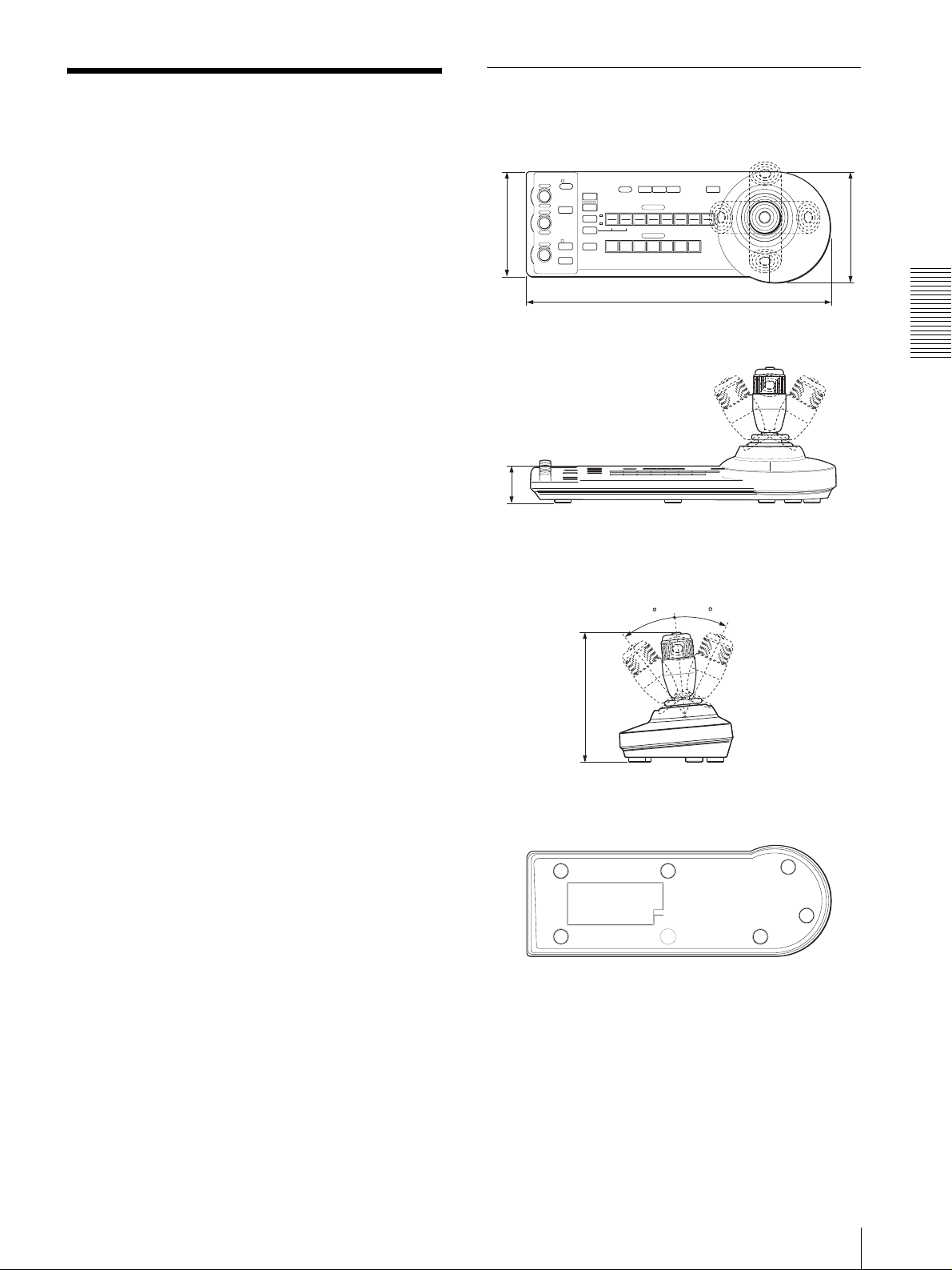
Spécifications
Dimensions
Connecteurs d’entrée/sortie
Entrées/sorties de commande
VISCA RS-232C OUT : Type mini-
DIN 8 broches
VISCA RS-422 : Type 9 broches
TALLY IN/CONTACT OUT : Type 9
broches
Format de signal de commande
9 600/38 400 bit/s
Données : 8 bits
Bit d’arrêt : 1
Connecteur d’alimentation
JEITA type 4 (DC IN 12V)
Généralités
Tension d’entrée
12 V CC (10,8 à 13,2 V CC)
Consommation de courant
0,2 A maximum. (à 12 V CC), 2,4 W
Température de fonctionnement
0 à +40 ºC (32 à 104 ºF)
Température de stockage
–20 à +60 ºC (–4 à 140 ºF)
Dimensions 391,3 × 185 × 145,9 mm (l/h/p)
1
(15
/2 × 7 3/8 × 5 3/4 pouces)
Poids 950 g (2 livres 15 onces) environ
Accessoires fournis
Adaptateur secteur MPA-AC1 (Sony) (1)
Cordon d’alimentation secteur (1)
Câble de raccordement RS-232C (1)
Fiche de connexion RS-422 (2)
Mode d’emploi (1)
La conception et les spécifications sont susceptibles
d’être modifiées sans préavis.
Face supérieure
VALUE
– +
BRIGHT
– +
FOCUS
NEAR FAR
LOCK
RESET
R
PRESET
MODE
SHIFT
L/R
DIRECTION
B
AUTO
AUTO
POWER
MANUAL
ONE PUSH
AF
)
2
/
1
(5
137,2
Face avant
)
16
/
13
(1
45,9
Face latérale
)
8
/
3
(7
185
Face inférieure
PANEL
BLACK
PAN-TILT
LIGHT
LIGHT
RESET
POSITION
2
3114
1
9
10
12
STD REV
CAMERA
1
234567
391,3 (15 1/2)
30
ONE PUSH
AWB
5136147158
30
MENU
16
)
4
/
3
(5
145,9
Annexe
Unité : mm (pouces)
Spécifications
17
FR
Page 36

Brochage
Connecteur de sortie VISCA RS-232C (mini DIN
8 broches, femelle)
Connecteur TALLY/CONTACT (fiche de
connexion, 9 broches)
TALLY/CONTACT
RS-232C
N° de broche Fonction
1 CAMERA1
N° de broche Fonction
1 Pas de connexion
2 Pas de connexion
Annexe
3 TXD IN
4 GND
5 RXD IN
6 GND
7 Pas de connexion
8 Pas de connexion
2 CAMERA2
3 CAMERA3
4 CAMERA4
5 CAMERA5
6 CAMERA6
7 CAMERA7
8 GND
9 GND
19
Connecteur VISCA RS-422 (fiche de connexion,
9 broches)
VISCA
RS-422
19
N° de broche Fonction
1 Pas de connexion
2 Pas de connexion
3 Pas de connexion
4 Pas de connexion
5 GND
6 RXD IN–
7 RXD IN+
8 TXD IN–
9 TXD IN+
FR
18
Spécifications
Page 37
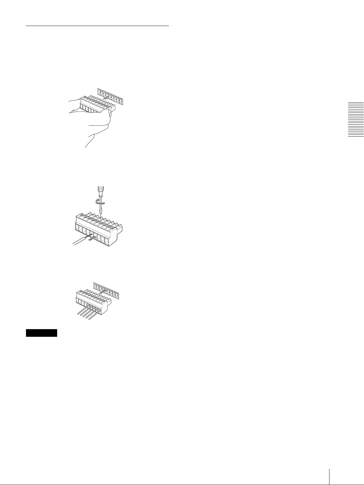
Utilisation de la fiche de connexion
VISCA RS-422
1
Prenez la fiche de connexion VISCA RS-422 aux
deux extrémités et retirez-la comme sur
l’illustration.
1
9
2
Insérez un fil (AWG n° 28 à 18) dans l’orifice désiré
de la fiche et serrez la vis pour ce fil à l’aide d’un
tournevis à lame plate.
Tournevis à lame plate
Annexe
Fil
3
Insérez la fiche de connexion VISCA RS-422 dans
le connecteur VISCA RS-422.
1
9
Remarques
• Pour stabiliser le niveau de tension du signal,
raccordez les deux extrémités à la terre (GND).
• Lorsque les raccordements sont effectués à l’aide des
connecteurs VISCA RS-422, la connexion VISCA
RS-232C n’est pas disponible.
• La distance de raccordement maximale avec la
connexion VISCA RS-422 est d’environ 1 200 m
(3 937 pieds).
Spécifications
19
FR
Page 38

ADVERTENCIA
Para reducir el riesgo de incendio o
electrocución, no exponga este producto
a la lluvia ni a la humedad.
Para evitar descargas eléctricas, no abra
el aparato. Solicite asistencia técnica
únicamente a personal especializado.
ADVERTENCIA
Utilice el adaptador de alimentación de CA MPA-AC1
Sony provisto con este equipo como fuente de
alimentación. Cualquier otra fuente de alimentación
podrá resultar en peligros tales como un incendio.
El dispositivo de desconexión de este equipo es la clavija
de conexión a la red del adaptador de CA.
Para desconectar la alimentación de la red deberá
utilizarse la clavija de conexión a la red de este equipo.
Por favor, asegúrese de que la toma de corriente esté
instalada cerca del equipo y que sea fácilmente
accesible.
En caso de operaciones anormales, desconecte la clavija
de conexión a la red.
IMPORTANTE
La placa de datos se encuentra en la parte inferior.
ATENCIÓ N
Los campos electromagnéticos en las frecuencias
específicas pueden influir sobre la imagen de esta
unidad.
ES
2
Page 39

Índice
Descripción general
Características ....................................................... 4
Precauciones ........................................................... 4
Ubicación y función de componentes ................... 5
Funciones disponibles para las cámaras Sony
VISCA .............................................................. 8
Conexiones y operaciones
Conexiones ............................................................. 9
Conexión de una cámara equipada con conector
VISCA RS-232C .............................................. 9
Conexión de una cámara equipada con conector
VISCA RS-422 ...............................................10
Conexión de múltiples cámaras equipadas con
conector VISCA RS-232C ............................. 10
Conexión de múltiples cámaras equipadas con
conector VISCA RS-422 ................................ 11
Conexión de la unidad de multiplexación óptica
BRU-300/300P ............................................... 12
Conexión de un conmutador de vídeo .............. 13
Encendido de la alimentación ............................. 13
Almacenamiento de los ajustes de la cámara en la
memoria – Función de preajuste ........................ 14
Ajuste de la velocidad del movimiento de la
cámara a una posición predeterminada
(BRC-300/300P y BRC-H700/H700P
solamente) ...................................................... 15
ES
Apéndice
Solución de problemas ........................................ 16
Especificaciones ................................................... 17
Dimensiones ..................................................... 17
Asignaciones de terminales .............................. 18
Uso de la clavija de conector
VISCA RS-422 ...............................................19
Índice
ES
3
Page 40

Descripción general
Precauciones
Lugar de funcionamiento o
Descripción general
Características
La palanca de control óptica de tres ejes
permite realizar cómodamente operaciones de
movimiento horizontal/vertical/zoom.
Fácil realización de ajustes de cámara versátiles
Utilizando los botones de la unidad, usted podrá realizar
fácilmente varios ajustes de la cámara tales como
enfoque automático, ajuste del enfoque automático con
un solo toque, ajuste AE, ajuste del balance del blanco
automático con un solo toque y compensación de la
iluminación de fondo.
Las interfaces de comunicación VISCA RS232C/RS-422 permiten comunicación a alta
velocidad a larga distancia.
La unidad puede controlar hasta siete cámaras
conectadas en cadena.
Un terminal de entrada con lámpara indicadora/
salida de terminal (clavija de conector de
9 terminales) permite conectar un conmutador
de vídeo.
almacenamiento
La unidad podrá dañarse se si utiliza o guarda en los
lugares siguientes:
• Lugares extremadamente cálidos o fríos (temperatura
de funcionamiento: 0
• Lugares expuestos a la luz solar directa durante
periodos prolongados o cerca de equipos de
calefacción (por ejemplo, radiadores)
• Cerca de fuentes de magnetismo intenso
• Cerca de fuentes de radiación electromagnética
intensa como radios o transmisores de TV
• Lugares expuestos a golpes o vibraciones intensas
°C a +40°C [32°F a 104°F])
Ventilación
Para evitar la acumulación de calor, no bloquee la
circulación del aire alrededor de la unidad.
Transporte
Cuando transporte la unidad, vuelva a empaquetarla
como estaba empaquetada originalmente de fábrica o en
materiales de igual calidad.
Función de preajuste para guardar ajustes de la
cámara
La unidad permite guardar hasta 16 combinaciones* de
ajustes de cámara tales como posiciones de movimiento
horizontal/vertical/zoom y otros valores de ajustes de
cámara en la memoria de la cámara.
* El número de posiciones que se pueden guardar varía
dependiendo de la cámara conectada. (Para la cámara
de vídeo en color BRC-300/300P 3CCD se puede
guardar 6 posiciones.)
Cámaras Sony VISCA que se pueden
controlar
La unidad puede controlar las cámaras siguientes:
• BRC-300/300P 3CCD Color Video Camera
• BRC-H700/H700P HD 3CCD Color Video Camera
• EVI-D100/D100P Color Video Camera
• EVI-D70/D70P Color Video Camera
• EVI-D30/D30P Color Video Camera
• SNC-RZ30N/RZ30P Network Camera
Notas
• Las funciones operables están limitadas a aquellas con
las que está equipada la cámara.
• Este manual explica principalmente las funciones de
la unidad para la cámara BRC-300/300P.
Si hay otra cámara conectada, consulte el manual
instrucciones que se suministran con la cámara
conectada para ver las funciones disponibles.
Limpieza
• Para limpiar las superficies externas de la unidad
utilice un paño suave y seco. Para eliminar las
manchas difíciles, utilice un paño suave humedecido
con una pequeña cantidad de solución detergente y a
continuación seque la unidad con un paño.
• No utilice disolventes volátiles, como alcohol,
bencina o diluyentes, ya que pueden dañar los
acabados de la superficie.
ES
4
Características / Precauciones
Page 41
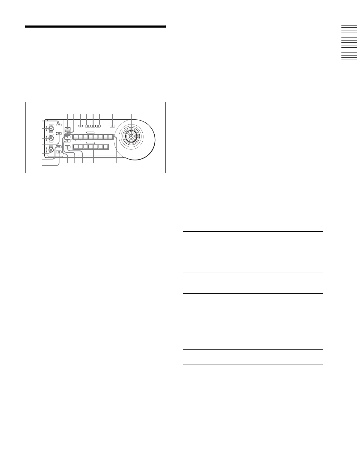
Ubicación y función de
qhqjqkq
w
componentes
Este manual se centra en el funcionamiento de la RMBR300 cuando se utiliza con la cámara BRC-300/300P
o BRC-H700/H700P.
Parte delantera
90qaqsqd qf qg
8
1
VALUE
– +
BRIGHT
– +
NEAR FAR
LOCK
R
MODE
B
AUTO
FOCUS
AUTO
MANUAL
ONE PUSH
AF
2
3
4
5
6
7
A Botón e indicador LOCK
Pulse el botón LOCK durante más de un segundo, y
se encenderá el indicador LOCK y se bloquearán
los valores establecidos por los controles VALUE/
R, BRIGHT/B y FOCUS. (Los indicadores de los
controles bloqueados se apagarán.)
También se inhabilitará el botón AUTO/MANUAL.
Pulse el botón LOCK durante más de un segundo
otra vez para desbloquear los controles y los
botones.
B Control VALUE/R
Cuando se seleccione el modo de ajuste del brillo
con el botón MODE (con el indicador VALUE
encendido):
Este control ajusta el valor del elemento
(SHUTTER o IRIS) seleccionado en la cámara.
Cuando el indicador VALUE esté encendido, la
función del control variará de acuerdo con el modo
de exposición seleccionado en la cámara. Para más
detalles, consulte “Funciones de los controles
VALUE y BRIGHT” en página 5.
Cuando se seleccione el modo de ajuste del
balance del blanco con el botón MODE (con el
indicador R encendido):
Este control ajusta el R. GAIN (ganancia de rojo)
(excepto la EVI-D30/D30P).
Cuando se conecta la cámara BRC-H700/H700P, la
función del control con el indicador R encendido
variará de acuerdo con el modo del balance del
blanco seleccionado en la cámara. Para más
detalles, consulte “Funciones de los controles R y B
para la cámara BRC-H700/H700P” en página 6.
PRESET
DIRECTION
POWER
RESET
1
SHIFT
9
STD REV
L/R
1
PANEL
BLACK
PAN-TILT
ONE PUSH
LIGHT
LIGHT
RESET
AWB
POSITION
2
3114
5136147158
12
10
CAMERA
234567
l
MENU
16
;
C Control BRIGHT/B
Cuando se seleccione el modo de ajuste del brillo
con el botón MODE (con el indicador BRIGHT
encendido):
Este control ajusta el valor del brillo de la cámara,
etc.
Cuando el indicador BRIGHT esté encendido, la
función del control variará de acuerdo con el modo
de exposición seleccionado en la cámara. Para más
detalles, consulte “Funciones de los controles
VALUE y BRIGHT” en página 5.
Cuando se seleccione el modo de ajuste del
balance del blanco con el botón MODE (con el
indicador B encendido):
Este control ajusta el B. GAIN (ganancia de azul)
(excepto la EVI-D30/D30P).
Cuando se conecta la cámara BRC-H700/H700P, la
función del control con el indicador B encendido
variará de acuerdo con el modo del balance del
blanco seleccionado en la cámara. Para más
detalles, consulte “Funciones de los controles R y B
para la cámara BRC-H700/H700P” en página 6.
Funciones de los controles VALUE y BRIGHT
Las funciones del control VALUE y el control BRIGHT
cambiarán de acuerdo con el ajuste del modo de
exposición de la cámara, de la forma siguiente:
Modo de
exposición de la
cámara
FULL AUTO No se utiliza Control de nivel de
SHUTTER Pri Control de
IRIS Pri Control de
BRIGHT No se utiliza Control de nivel de
MANUAL Control de
GAIN Pri*** Control de
* Cuando esté activada la función de compensación de
exposición en la cámara.
** Para la cámara BRC-H700/H700P es posible el control de
diafragma + ganancia.
*** Sólo está disponible para la cámara BRC-H700/H700P
Función de
control VALUE
velocidad del
obturador
diafragma
velocidad del
obturador
ganancia***
Función de
control BRIGHT
compensación de
exposición*
Control de nivel de
compensación de
exposición*
Control de nivel de
compensación de
exposición*
brillo
Control de
diafragma**
No se utiliza
Descripción general
ES
Ubicación y función de componentes
5
Page 42

Funciones de los controles R y B para la
cámara BRC-H700/H700P
Cuando se selecciona el modo de ajuste del balance del
blanco con el botón MODE de esta unidad, las funciones
del control R y del control B cambian de acuerdo con la
Descripción general
configuración del modo del balance del blanco de la
cámara BRC-H700/H700P.
I Botón PRESET
Mantenga pulsado este botón y pulse uno de los
botones POSITION, y la configuración actual de la
cámara se almacenará en la memoria de la cámara
correspondiente al botón POSITION pulsado.
J Botón PANEL LIGHT
Pulse este botón para iluminar todos los botones
Modo de balance
del blanco de la
cámara
MANUAL Control de
AUTO, ONE
PUSH
Función del
control R
ganancia del rojo
Control WB
SHIFT del rojo
Función del
control B
Control de
ganancia del azul
Control WB
SHIFT del azul
POSITION y botones CAMERA. Pulse de nuevo el
botón para apagar la iluminación.
K Botón BACK LIGHT
Cuando seleccione el modo de exposición FULL
AUTO en la cámara, pulse este botón para habilitar
la función de compensación de la iluminación de
fondo de la cámara. Púlselo de nuevo para
D Botón MODE
desactivar la función.
Pulse este botón para seleccionar la función del
control VALUE/R y del control BRIGHT/B.
Cuando se selecciona el modo de ajuste de brillo, se
encienden los indicadores VALUE y BRIGHT.
Cuando se selecciona el modo de ajuste de balance
de blancos, se encienden los indicadores R y B.
E Control FOCUS
Cuando se seleccione MANUAL con el botón
AUTO/MANUAL este control estará inhabilitado.
Gire el control hacia la izquierda (hacia NEAR)
para enfocar un motivo cercano, y hacia la derecha
(hacia FAR) para enfocar un motivo lejano.
F Botón AUTO/MANUAL e indicador AUTO
Pulse este botón para seleccionar el modo de
enfoque AUTO o MANUAL.
Cuando se seleccione AUTO, se encenderá el
indicador AUTO y la cámara enfocará
automáticamente el motivo situado en el centro de
Para la cámara BRC-H700/H700P, mantenga
pulsado el botón SHIFT y pulse este botón para
habilitar la función de compensación de luz puntual
de la cámara. Esta función ajusta la exposición en
un nivel más oscuro si una parte del objeto grabado
está iluminada. Para deshabilitar la compensación
de luz puntual, mantenga pulsado el botón SHIFT y
pulse de nuevo este botón.
L Botón PAN-TILT RESET
Pulse este botón para reponer la posición de
movimiento horizontal/vertical de la cámara en las
condiciones iniciales.
M Botón ONE PUSH AWB
Cuando seleccione el modo de balance del blanco
ONE PUSH en la cámara, pulse este botón para
realizar el ajuste del balance del blanco con un solo
toque.
la pantalla. El control FOCUS y el botón ONE
PUSH AF estarán inhabilitados.
Cuando se selecciona MANUAL, el control
FOCUS y el botón ONE PUSH AF se activan (con
el indicador FOCUS encendido).
N Botón MENU
En la cámara BRC-300/300P o BRC-H700/H700P,
pulse este botón durante un segundo más o menos
para visualizar el menú de la cámara, volver al
menú principal o quitar el menú.
G Botón ONE PUSH AF
Cuando se seleccione MANUAL con el botón
AUTO/MANUAL este botón estará inhabilitado.
En otras cámaras, pulse este botón durante un
segundo más o menos para activar o desactivar la
visualización de datos en pantalla.
Pulse el botón para realizar la función de enfoque
automático con un solo toque (excepto la EVI-D30/
D30P).
O Palanca de control
La palanca de control se utiliza para las operaciones
de movimiento horizontal/vertical y zoom.
H Botón RESET
Mantenga pulsado este botón y pulse uno de los
botones POSITION, y la memoria de la cámara
Seleccione la cámara que quiera controlar
utilizando los botones CAMERA y accione la
palanca de control.
correspondiente al botón POSITION pulsado
recuperará el valor preestablecido de fábrica.
Cuando haya conectadas múltiples cámaras, las
direcciones de cámaras se ajustarán manteniendo
pulsado este botón y pulsando el botón POWER.
Movimiento horizontal/vertical
Al inclinar la palanca de control a derecha a
izquierda, la cámara se mueve horizontalmente. Al
inclinarlo hacia adelante o hacia atrás, la cámara se
mueve verticalmente.
ES
6
Ubicación y función de componentes
Page 43

La velocidad de movimiento horizontal/vertical
cambia según el ángulo de inclinación.
Al soltar la palanca de control, el movimiento de la
cámara se interrumpe.
S Botones CAMERA
Pulse uno de los botones para seleccionar la cámara
entre las conectadas. El botón CAMERA
seleccionado se encenderá en azul.
Uso del zoom
Al girar el disco situado en la parte superior de la
palanca de control de izquierda a derecha, el sujeto
se hace más grande (se acerca). Al girarlo de
derecha a izquierda, el sujeto se hace más pequeño
(se aleja).
Para volver a colocar la cámara en sentido
frontal
Al pulsar el botón situado en la parte superior de la
palanca de control durante uno o dos segundos con
o sin el menú visualizado, los movimientos
horizontal/vertical y zoom se ponen a cero y la
cámara vuelve a su posición frontal.
P Botón e indicadores SHIFT
Pulse este botón durante más de un segundo para
seleccionar la función de los botones POSITION
para posiciones 1 a 8 o posiciones 9 a 16.
El indicador superior se enciende para las
posiciones 1 a 8 y el indicador inferior para las
posiciones 9 a 16.
Para la cámara BRC-H700/H700P, mantenga
pulsado el botón SHIFT y pulse uno de los botones
POSITION. El indicador inferior se iluminará, y
podrá utilizar los botones POSITION para las
posiciones 9 a 16. Si suelta el botón SHIFT, el
indicador superior se iluminará y podrá utilizar los
botones POSITION para las posiciones 1 a 8.
Q Botón L/R DIRECTION
La cámara está preajustada para orientarse hacia la
derecha siempre que la palanca de control se incline
hacia la derecha. Mantenga pulsado este botón y
pulse el botón POSITION 2 (REV) para invertir la
dirección de movimiento horizontal en la dirección
de inclinación de la palanca de control. Para
restablecer la dirección, mantenga pulsado este
botón y pulse el botón POSITION 1 (STD).
T Botones POSITION
Usted podrá almacenar varios ajustes de la cámara
tales como las posiciones de movimiento
horizontal/vertical y zoom en la memoria de la
cámara correspondientes a cada botón POSITION,
y cargar los ajustes almacenados en la memoria.
Funciones de los botones POSITION para
las cámaras EVI-D100/D100P y EVI-D70/
D70P
Cuando se conecta una cámara EVI-D100/D100P o
EVI-D70/D70P a esta unidad, la unidad detecta
automáticamente el modelo de cámara, y las funciones
de las posiciones 7 a 16 de los botones POSITION
cambian según la tabla siguiente. Esto permite controlar
directamente la cámara sin conectarla a un ordenador.
Botón
POSITION
Posición 7 Exposición automática – Modo Full Auto
Posición 8 Exposición automática – Modo Bright
Posición 9 Zoom digital – Activado
Posición 10 Zoom digital – Desactivado
Posición 11 Modo de balance del blanco automático
Posición 12 Modo de balance del blanco manual
Posición 13 Modo de balance del blanco One Push
Posición 14 Modo de seguimiento automático de
Posición 15 IR Cut-Removable (ICR) – Activado
Posición 16 IR Cut-Removable (ICR) – Desactivado
Para obtener información detallada acerca de cada
función, consulte el Manual Técnico de la cámara.
Parte trasera/Parte inferior
Función
balance del blanco (ATW)
Descripción general
R Botón POWER
Pulse este botón para encender el botón(es)
CAMERA correspondiente al estado de la
cámara(s) conectada.
Azul: La alimentación de la cámara está activada.
Amarillo verde: La cámara está en el modo de
espera.
Apagado: No hay cámara conectada.
Mantenga pulsado este botón y pulse el botón
CAMERA 1 a 7 para encender/apagar la
alimentación de la cámara correspondiente al botón
pulsado.
MODE
RS-232C
RS-422 ON/OFF
VISCA
1919
TALLY/CONTACT
CONTACT(TALLY)
TALLY
CONTACT DC IN 12V
!
ws wd wf wg wh wj wkwa
U Selector MODE
Seleccione la posición correspondiente a la cámara
controlable por VISCA que se va a conectar.
Ubicación y función de componentes
ES
7
Page 44

Posición del
conmutador
0 Seleccionado automáticamente
Descripción general
1 BRC-300/300P
2 EVI-D70/D70P
3 EVI-D100/D100P
4 EVI-D30/D30P
5SNC-RZ30N/RZ30P
6 BRC-H700/H700P
Modo cámara
(por omisión)
Seleccione la función del conector TALLY/
CONTACT.
TAL LY: La luz indicadora de la cámara
seleccionada con el conmutador conectado se
enciende.
CONTACT: La salida de contacto correspondiente
a la dirección de la cámara seleccionada con esta
unidad está cortocircuitada con el conmutador
conectado.
CONTACT (TALLY): La salida de contacto
correspondiente a la dirección de la cámara
seleccionada con esta unidad está cortocircuitada
Notas
• Utilice la posición 1 a 4 cuando todas cámaras
con el conmutador conectado y la luz indicadora de
la cámara seleccionada con el conmutador
conectado se enciende.
conectadas sean del mismo modelo.
• Asegúrese de utilizar la posición 5 para la SNC-
RZ30N/RZ30P.
V Conector VISCA RS-232C
Se conecta al conector VISCA RS-232C IN de la
cámara o a la unidad de multiplexación óptica.
W Conector VISCA RS-422
Se conecta al conector VISCA RS-422 de la cámara
wh Conector DC IN 12V
Conecte el adaptador de alimentación de CA
suministrado.
wj Interruptores DIP (parte inferior)
Interruptor 1 (Selector RS-232C/RS-422)
Ajústese en ON para RS-422, o en OFF para RS-
232C.
o a la unidad de multiplexación óptica.
La instalación de fábrica incluye una clavija de
conector RS-422.
Interruptor 2 (Selector de velocidad de
transferencia de comunicación)
Ajústese en ON para 38400 bps, o en OFF para
X Conector TALLY/CONTACT
9600 bps.
Este conector se utiliza para la entrada de la luz
indicadora o la salida de contacto.
Seleccione la función del conector mediante el
selector TALLY/CONTACT.
wk Interruptor ON/OFF
Pulse este interruptor para encender/apagar esta
unidad.
La instalación de fábrica incluye una clavija de
conector RS-422.
Y Selector TALLY/CONTACT
Nota
Ajuste los interruptores antes de conectar la
Funciones disponibles para las cámaras Sony VISCA
Las funciones de los controles, botones y conectores de la lista siguiente varían en función del modelo de cámara
conectada. Las funciones de las demás partes son las mismas para todos los modelos de cámara.
Partes BRC-300/
B Control VALUE/R a a a
C Control BRIGHT/B a a a
G Botón ONE PUSH AF a a a
L Botón PAN-TILT RESET a a a a
N Botón MENU a a a a
R Botón POWER a a a a
S Botones CAMERA a a a a
W Conector VISCA RS-422 a
a: disponible, ×: no disponible
ES
8
Ubicación y función de componentes
300P, BRC-
H700/H700P
EVI-D100/
D100P
×
EVI-D70/
D70P
a
EVI-D30/
D30P
×
×
×
× ×
SNC-RZ30N/
RZ30P
a
a
a
×
×
×
×
Page 45

Conexiones y operaciones
Nota
Cuando utilice los conectores VISCA RS-232C,
compruebe que el interruptor DIP de la parte inferior de
esta unidad (página 8) esté ajustado a RS-232C.
Conexiones
Esta sección se centra en los ejemplos de conexión para
la cámara BRC-300/300P. Para las conexiones con otras
cámaras, consulte el manual instrucciones que se
suministran con la cámara que vaya a conectar.
Conexión de una cámara equipada
con conector VISCA RS-232C
1
Conecte esta unidad a la cámara utilizando el cable
de conector RS-232C suministrado con esta unidad.
2
Conecte esta unidad a una toma de CA utilizando el
adaptador de CA y el cable de alimentación de CA
suministrados.
Cámara BRC-300/300P
Cables de conexión
Utilice los siguientes cables de conexión para conectar
dispositivos a este sistema.
Cable N.° de parte Número
Cable RS-232C
(3 m (10 pies))
Cable RS-232C
1-590-879-3X 1
Conexiones y operaciones
R
1 2 3 4 5 6 7 8 9
1 2 3
OFF ON
IR SELECT
75
EXT SYNC IN
VIDEO S VIDEO
Adaptador de alimentación de CA
MPA-AC1 (suministrado)
VISCA RS-422
!
IN VISCA RS-232C OUT
DC IN
12V
VISCA RS-232C IN
Cable RS-232C (suministrado)
(SONY: 1-590-879-3X)
VISCA RS-232C
DC IN 12V
a toma de CA
Cable de
alimentación de
CA
(suministrado)
a toma de CA
Conexiones
ES
9
Page 46

Conexión de una cámara equipada
Conexión de múltiples cámaras
con conector VISCA RS-422
Usted podrá utilizar los conectores VISCA RS-422 para
conectar esta unidad a la cámara en lugar de los
conectores VISCA RS-232C. El uso de los conectores
VISCA RS-422 permite la conexión a una distancia
hasta 1.200 m (3.937 pies).
equipadas con conector VISCA RS232C
Las conexiones con los cables VISCA RS-232C (tipo
cruzado) permiten controlar hasta siete cámaras con una
sola unidad de mando a distancia RM-BR300.
Prepare el cable de conexión utilizando las clavijas de
Conexiones y operaciones
conector RS-422 que vienen con esta unidad.
Para hacer el cable, consulte las asignaciones de
terminales del conector VISCA RS-422 (página 18).
Para utilizar las clavijas de conector RS-422, consulte
página 19.
Cámara BRC-300/300P
a toma de CA
VISCA RS-422
VISCA RS-232C
Cámara BRC300/300P
EXT SYNC IN
OFF ON
75
1 2 3
IR SELECT
VIDEO S VIDEO
R
1 2 3 4 5 6 7 8 9
IN VISCA RS-232C OUT
VISCA RS-422
Cable RS-232C
(suministrado)
(SONY: 1-590-879-3X)
a VISCA RS-232C IN
!
DC IN
12V
a toma de CA
a toma de CA
Cable VISCA RS-422
VISCA RS-422
DC IN 12V
Cable de
alimentación de
CA
(suministrado)
a toma de CA
Adaptador de alimentación de CA
MPA-AC1 (suministrado)
Notas
• Cuando utilice los conectores VISCA RS-422,
compruebe que el interruptor DIP de la parte inferior
de esta unidad (página 8) esté ajustado a RS-422.
• Cuando se realicen las conexiones mediante los
conectores VISCA RS-422, la conexión VISCA RS232C no estará disponible.
Primera cámara
VISCA RS-232C OUT
Cable RS-232C
VISCA RS-232C IN
R
1 2 3 4 5 6 7 8 9
1 2 3
OFF ON
IR SELECT
75
EXT SYNC IN
VIDEO S VIDEO
Segunda cámara
VISCA RS-422
IN VISCA RS-232C OUT
VISCA RS-232C OUT
Cable RS-232C
VISCA RS-232C IN
R
1 2 3 4 5 6 7 8 9
1 2 3
OFF ON
IR SELECT
EXT SYNC IN
75
VIDEO S VIDEO
VISCA RS-422
IN VISCA RS-232C OUT
Tercera a séptima cámara
!
DC IN
12V
!
DC IN
12V
a toma de CA
a toma de CA
ES
10
Conexiones
Page 47

Nota
Cuando utilice los conectores VISCA RS-232C,
compruebe que el interruptor DIP de la parte inferior de
esta unidad (página 8) esté ajustado a RS-232C.
Para asignar direcciones de cámaras
Antes de ponerlas en funcionamiento, debe asignar las
direcciones de cámara a las cámaras conectadas, del
modo siguiente. A continuación, puede cambiar la
cámara que se va a controlar simplemente pulsando el
botón CAMERA correspondiente.
Cámara
BRC-300/300P
VISCA
RS-422
a toma de CA
Conexiones y operaciones
1
Conecte la alimentación de todas las cámaras
conectadas y de esta unidad.
2
Mantenga pulsado el botón RESET y pulse el botón
POWER de esta unidad.
La unidad reconocerá las cámaras conectadas y les
asignará las direcciones de cámaras 1 a 7
automáticamente en el orden de conexión.
3
Pulse el botón POWER de esta unidad y compruebe
que los botones CAMERA se encienden.
El número de los botones CAMERA encendidos
indica cuántas cámaras tienen las direcciones
asignadas.
Ahora usted podrá elegir la cámara que quiera
controlar pulsando el botón CAMERA.
Conexión de múltiples cámaras
equipadas con conector VISCA RS422
La conexión mediante los conectores VISCA RS-422
permite el control de múltiples cámaras. Esto permite la
conexión en una distancia hasta 1.200 m (3.937 pies).
Prepare el cable de conexión utilizando la clavija de
conector RS-422 que vienen con esta unidad.
Para hacer el cable, consulte las asignaciones de
terminales del conector VISCA RS-422 (página 18).
Para utilizar las clavijas de conexión RS-422, consulte
página 19.
Para ver el diagrama de cableado de conexión de VISCA
RS-422, consulte el manual de instrucciones
suministrado con la BRC-300/300P.
R
1 2 3 4 5 6 7 8 9
1 2 3
OFF ON
IR SELECT
EXT SYNC IN
75
VIDEO S VIDEO
VISCA RS-422
IN VISCA RS-232C OUT
Primera cámara
R
1 2 3 4 5 6 7 8 9
1 2 3
OFF ON
IR SELECT
EXT SYNC IN
75
VIDEO S VIDEO
VISCA RS-422
IN VISCA RS-232C OUT
Segunda cámara
R
1 2 3 4 5 6 7 8 9
1 2 3
OFF ON
IR SELECT
EXT SYNC IN
75
VIDEO S VIDEO
VISCA RS-422
IN VISCA RS-232C OUT
Tercera a séptima cámara
Cable VISCA RS-422
a VISCA RS-422
!
DC IN
12V
a toma de CA
VISCA RS-422
Cable VISCA RS-422
VISCA RS-422
!
DC IN
12V
a toma de CA
VISCA RS-422
Cable VISCA RS-422
VISCA RS-422
!
DC IN
12V
a toma de CA
Notas
• Cuando utilice los conectores VISCA RS-422,
compruebe que el interruptor DIP de la parte inferior
de esta unidad (página 8) esté ajustado a RS-422.
• Cuando se realicen las conexiones mediante los
conectores VISCA RS-422, la conexión VISCA RS232C no estará disponible.
Conexiones
11
ES
Page 48
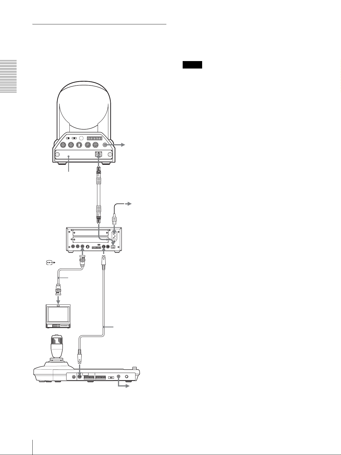
Conexión de la unidad de
multiplexación óptica BRU-300/
300P
Para controlar la cámara BRC-H700/H700P, puede
utilizar la unidad óptica múltiplex BRU-H700/H700P.
Para ver información detallada sobre la conexión,
consulte el manual instrucciones que se suministran con
la BRC-H700/H700P.
Usted podrá controlar la cámara utilizando esta unidad a
través de la unidad de multiplexación óptica BRU-300/
300P (no suministrada).
Nota
Cuando utilice los conectores VISCA RS-232C o los
conectores VISCA RS-422, compruebe que el
interruptor VISCA FUNCTION de la parte trasera de la
Conexiones y operaciones
Cámara BRC-300/300P
unidad de multiplexación óptica y el interruptor DIP de
la parte inferior de esta unidad (página 8) estén
ajustados a RS-232C o RS-422 correctamente.
R
1 2 3 4 5 6 7 8 9
1 2 3
OFF ON
IR SELECT
EXT SYNC IN
75
VIDEO S VIDEO
VISCA RS-422
IN VISCA RS-232C OUT
!
DC IN
12V
a toma de CA
Tarjeta de
multiplexación
óptica BRBK-303
CAMERA
T VIDEO
(o S VIDEO)
Cable coaxial
de 75 ohmios
(o cable SVideo)
Monitor de vídeo, etc.
Cable de fibra óptica
CCFC-M100
a toma de CA
Cable de
alimentación de CA
(suministrado con la
BRU-300/300P)
Unidad de
multiplexación óptica
BRU-300/300P
VISCA RS-232C IN
Cable RS-232C
(suministrado)*
(SONY: 1-590-879-3X)
ES
VISCA RS-232C
a toma de CA
* También dispone de la conexión VISCA RS-422 si utiliza los
conectores VISCA RS-422.
12
Conexiones
Page 49
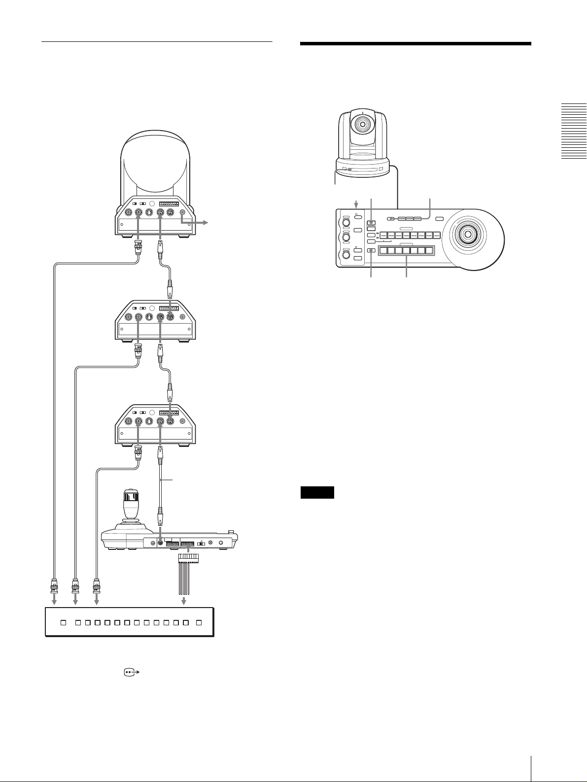
Conexión de un conmutador de
vídeo
Utilice un conmutador de vídeo de tipo de control por
contacto disponible en el comercio para cambiar entre
las múltiples señales de cámara que quiera sacar.
Cámara BRC-300/
Tercera a séptima
cámara
300P
Encendido de la
alimentación
Conexiones y operaciones
R
1 2 3 4 5 6 7 8 9
1 2 3
OFF ON
IR SELECT
75
EXT SYNC IN
T VIDEO
VISCA RS-422
IN VISCA RS-232C OUT
VIDEO S VIDEO
VISCA RS-232C IN
!
DC IN
12V
a toma de CA
Cable RS-232C
VISCA RS-232C OUT
R
1 2 3 4 5 6 7 8 9
VISCA RS-422
!
DC IN
IN VISCA RS-232C OUT
12V
VISCA RS-232C IN
Cable RS-232C
VISCA RS-232C OUT
R
1 2 3 4 5 6 7 8 9
VISCA RS-422
!
DC IN
IN VISCA RS-232C OUT
12V
Cable coaxial de 75 ohmios*
Segunda cámara
1 2 3
OFF ON
IR SELECT
75
EXT SYNC IN
VIDEO S VIDEO
T VIDEO
Primera cámara
1 2 3
OFF ON
IR SELECT
75
EXT SYNC IN
VIDEO S VIDEO
VISCA RS-232C IN
Cable coaxial de 75 ohmios*
Cable RS-232C
(suministrado)
(SONY: 1-590-879-3X)
VISCA RS-232C
MODE
RS-232C
VISCA
1919
CONTACT(TALLY)
RS-422 ON/OFF
TALLY/CO NTA CT
!
TALLY
CONTACT DC IN 12V
TALLY/CONTACT
a entrada de vídeo compuesto
Cable coaxial de 75 ohmios*
al terminal de
control por contacto
Conmutador de vídeo (disponible en el mercado)
* También puede utilizar un cable de conexión S-Video para
conectar el conector S VIDEO de la cámara y el conector
de la entrada S-Video del conmutador de vídeo.
Para la conexión con un conmutador de vídeo, consulte
el manual de instrucciones del conmutador.
1 2
VALUE
– +
R
BRIGHT
– +
B
FOCUS
NEAR FAR
LOCK
MODE
AUTO
AUTO
MANUAL
ONE PUSH
AF
RESET
RESET
PRESET
SHIFT
L/R
DIRECTION
POWER
PANEL LIGHT
PANEL
BLACK
PAN-TILT
LIGHT
LIGHT
RESET
POSITION
1
2
3114
9
10
12
STD REV
CAMERA
1
234567
ONE PUSH
AWB
5136147158
MENU
16
POWER CAMERA
1
Conecte la cámara a la toma de CA.
Se conectará la alimentación de la cámara y se
iluminará el indicador POWER.
La cámara realizará automáticamente el
movimiento horizontal y vertical y se repondrá en
la posición almacenada en POSITION 1 (acción de
reposición de movimiento horizontal/vertical).
2
Pulse el interruptor ON/OFF de esta unidad para
encenderla.
Se encenderá el botón CAMERA que represente a
la cámara cuya alimentación fue desactivada la
última de todas. (El botón CAMERA 1 se
encenderá por omisión.)
3
Encienda los dispositivos periféricos.
Notas
• Asegúrese de conectar la alimentación de la cámara
antes de la alimentación de esta unidad. De lo
contrario, la unidad no podrá reconocer la cámara
conectada.
• No toque la palanca de control cuando esté
conectando la alimentación de la unidad. El hacerlo
podrá afectar a la confirmación del origen.
Para encender/apagar la cámara
utilizando esta unidad
Mientras la cámara esté conectada a la toma de CA,
usted podrá encenderla o apagarla con el botón POWER
de esta unidad.
A la vez que mantiene pulsado el botón POWER, pulse
el botón CAMERA correspondiente a la cámara que
desea encender/apagar.
Cuando desconecte la alimentación utilizando esta
unidad, se apagará el indicador POWER y se encenderá
el indicador STANDBY de la cámara.
Encendido de la alimentación
13
ES
Page 50
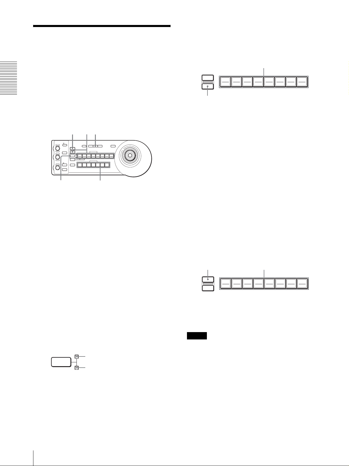
Almacenamiento de los
ajustes de la cámara en
5
A la vez que mantiene pulsado el botón PRESET,
pulse cualquiera de los botones POSITION, de 1 a
8, donde desee almacenar los ajustes. (excepto la
BRC-H700/H700P)
la memoria
– Función de preajuste
RESET
PRESET
Pulse un botón POSITION.
192103114125136147158
16
En la memoria de la cámara se pueden almacenar hasta
Conexiones y operaciones
dieciséis combinaciones de ajustes (dieciséis
Manteniendo pulsado
posiciones), incluyendo la posición de la cámara, zoom,
enfoque, e iluminación de fondo utilizando esta unidad.
Los ajustes se almacenan en la memoria de la
cámara.
RESET
51
El botón pulsado parpadeará durante el
almacenamiento. El parpadeo cesará cuando se
VALUE
– +
– +
NEAR FAR
LOCK
R
MODE
BRIGHT
B
AUTO
FOCUS
AUTO
MANUAL
ONE PUSH
AF
RESET
PRESET
1
SHIFT
9
STD REV
L/R
DIRECTION
POWER
1
PANEL
BLACK
PAN-TILT
ONE PUSH
LIGHT
LIGHT
RESET
AWB
POSITION
2
3114
5136147158
10
12
CAMERA
234567
MENU
16
haya completado el almacenamiento.
Para reactivar los ajustes almacenados
Seleccione la función de los botones POSITION 1 a 8
pulsando el botón SHIFT durante más de un segundo, si
24
es necesario. Pulse cualquiera de los botones
POSITION, de 1 a 8, donde haya almacenado los
1
Pulse el botón PAN-TILT RESET para reponer la
ajustes.
posición de movimiento horizontal/vertical.
Para cancelar la memoria preajustada
2
Pulse el botón CAMERA para seleccionar la
cámara cuyas configuraciones desea preajustar.
3
Ajuste los valores de posición, zoom, enfoque e
iluminación de fondo de la cámara.
Seleccione la función de los botones POSITION 1 a 8
mediante el botón SHIFT, si es necesario. A la vez que
mantiene pulsado el botón RESET, pulse el botón
POSITION desde el cual desee cancelar los ajustes.
4
Pulse el botón SHIFT durante más de un segundo
para seleccionar la función de los botones
POSITION 1 a 8, si es necesario. (excepto la BRCH700/H700P)
Para almacenar en las posiciones 1 a 8, pulse el
botón SHIFT para que se encienda el indicador
superior. Los botones 1 a 8 de POSITION pueden
utilizarse para las posiciones 1 a 8.
Para almacenar en las posiciones 9 a 16, pulse el
botón SHIFT para que se encienda el indicador
inferior. Los botones 1 a 8 de POSITION pueden
utilizarse para las posiciones 9 a 16.
SHIFT
para posiciones 1 a 8
para posiciones 9 a 16
Manteniendo pulsado
RESET
PRESET
192103114125136147158
Pulse un botón POSITION.
16
El botón pulsado parpadeará durante la cancelación de
los ajustes. El parpadeo cesará cuando los ajustes hayan
sido cancelados.
Notas
• Al encenderse la alimentación, la cámara empieza con
los ajustes almacenados en POSITION 1.
• Si desea conservar las anteriores posiciones de
movimiento horizontal y vertical al apagar y
reencender el equipo, almacene estas posiciones en
POSITION 1.
• Cuando almacene o cancele los ajustes en una
POSITION, no puede activar, almacenar o cancelar
los ajustes en otra POSITION.
ES
14
Almacenamiento de los ajustes de la cámara en la memoria – Función de preajuste
Page 51

Para seleccionar las posiciones 9 a 16
para la BRCH700/H700P
Mantenga pulsado el botón SHIFT y pulse el botón
PRESET (para almacenar o recuperar la configuración)
o el botón RESET (para cancelar la configuración). El
indicador inferior se iluminará, y podrá utilizar los
botones POSITION 1 a 8 para las posiciones 9 a 16.
Cuando suelte el botón SHIFT, el indicador superior se
iluminará, y podrá utilizar los botones POSITION 1 a 8
para las posiciones 1 a 8.
Para la BRC-H700/H700P, no es necesario pulsar el
botón SHIFT durante más de un segundo para cambiar
previamente el estado del indicador.
Ajuste de la velocidad del
movimiento de la cámara a una
posición predeterminada (BRC300/300P y BRC-H700/H700P
solamente)
Usted podrá seleccionar la velocidad de movimiento
horizontal y vertical cuando la cámara se mueva a una
posición predeterminada.
1
Pulse el botón CAMERA para seleccionar la
cámara cuya velocidad quiera ajustar.
2
Pulse el botón POSITION para el que quiera ajustar
la velocidad durante más de un segundo.
Parpadearán todos los botones CAMERA, 1 a 7.
3
Pulse uno de los botones CAMERA para
seleccionar la velocidad.
Conexiones y operaciones
Botón CAMERA Velocidad de movimiento
1 1 grado/segundo
2 2,2 grados/segundo
3 4,8 grados/segundo
4 11 grados/segundo
5 23,3 grados/segundo
6 43 grados/segundo
7 60 grados/segundo (por omisión)
Ahora la cámara se moverá a la posición
predeterminada en el botón POSITION pulsado a la
velocidad seleccionada.
horizontal y vertical
Para establecer la velocidad de la cámara
pasando a una posición preestablecida
para la BRC-H700/H700P
Para establecer la velocidad de la cámara pasando a una
posición preestablecida entre 9 y 16, mantenga pulsado
el botón SHIFT y pulse el botón POSITION
correspondiente.
Almacenamiento de los ajustes de la cámara en la memoria – Función de preajuste
15
ES
Page 52

Apéndice
Solución de problemas
Antes de traer su unidad para repararla, compruebe lo
siguiente a modo de guía para solucionar el problema.
Si el problema no se puede solucionar, consulte con un
concesionario Sony.
Síntoma Causa Solución
La alimentación de la unidad no está
Apéndice
activada.
La cámara no se puede operar con la
unidad.
La unidad no se puede operar en
absoluto. —
El adaptador de alimentación de CA no está
firmemente conectado a la toma DC IN 12V.
El cable de alimentación de CA no está
insertado firmemente en el adaptador de
alimentación de CA o a la toma de CA.
La conexión mediante los conectores VISCA
RS-422 no se ha realizado correctamente.
El ajuste de control VISCA no es correcto. Seleccione el ajuste apropiado (RS-232C o
El ajuste de velocidad de transferencia de
comunicación de la cámara y de la unidad
varía.
Inserte el cable de alimentación firmemente y
hasta el fondo.
Inserte el cable de alimentación firmemente y
hasta el fondo.
Compruebe que la conexión a los conectores
VISCA RS-422 se ha realizado correctamente
y que el cable RS-422 está correctamente
conectado.
RS-422) con el interruptor DIP de la unidad
(page 8).
Seleccione la velocidad de transferencia de
comunicación, 9.600 bps o 38.400 bps, con el
interruptor DIP de la unidad (page 8) que esté
seleccionada en la cámara.
Desenchufe el cable de alimentación de la
toma de CA y vuelva a enchufarlo
transcurridos unos segundos.
ES
16
Solución de problemas
Page 53

Especificaciones
Conectores de entrada/salida
Entrada/salida de control
VISCA RS-232C OUT: Tipo Mini DIN
de 8 terminales
VISCA RS-422: Tipo 9 terminales
TALLY IN/CONTACT OUT: Tipo
9terminales
Formato de señal de control
9600 bps/38400 bps
Datos: 8 bits
Bit de parada: 1
Conector de alimentación
JEITA tipo 4 (DC IN 12V)
Generalidades
Tensión de entrada
12 V CC (10,8 a 13,2 V CC)
Consumo de corriente
0,2 A máx. (a 12 V CC), 2,4 W
Temperatura de funcionamiento
0ºC a +40ºC (32ºF a 104ºF)
Temperatura de almacenamiento
–20ºC a +60ºC (-4ºF a 140ºF)
Dimensiones 391,3 × 185 × 145,9 mm (ancho/alto/
fondo)
1
(15
/2 × 7 3/8 × 5 3/4 pulgadas)
Peso Aprox. 950 g (2 lb 15 oz)
Accesorios suministrados
Adaptador de alimentación de CA MPA-AC1 (Sony) (1)
Cable de alimentación de CA (1)
Cable de conexión RS-232C (1)
Clavija de conexión RS-422 (2)
Manual de instrucciones (1)
Dimensiones
Superior
VALUE
– +
BRIGHT
– +
FOCUS
NEAR FAR
LOCK
RESET
R
PRESET
MODE
B
AUTO
MANUAL
ONE PUSH
1
SHIFT
9
STD REV
L/R
DIRECTION
AUTO
POWER
1
AF
)
8
/
3
(7
185
)
2
/
1
(5
137,2
Parte delantera
)
16
/
13
(1
45,9
Lateral
Parte inferior
PANEL
BLACK
PAN-TILT
ONE PUSH
LIGHT
LIGHT
RESET
AWB
POSITION
2
3114
5136147158
10
12
CAMERA
234567
391,3 (15 1/2)
30
30
MENU
16
)
4
/
3
(5
145,9
Apéndice
El diseño y las especificaciones pueden modificarse sin
previo aviso.
Unidad de medida: mm (pulgadas)
Especificaciones
17
ES
Page 54
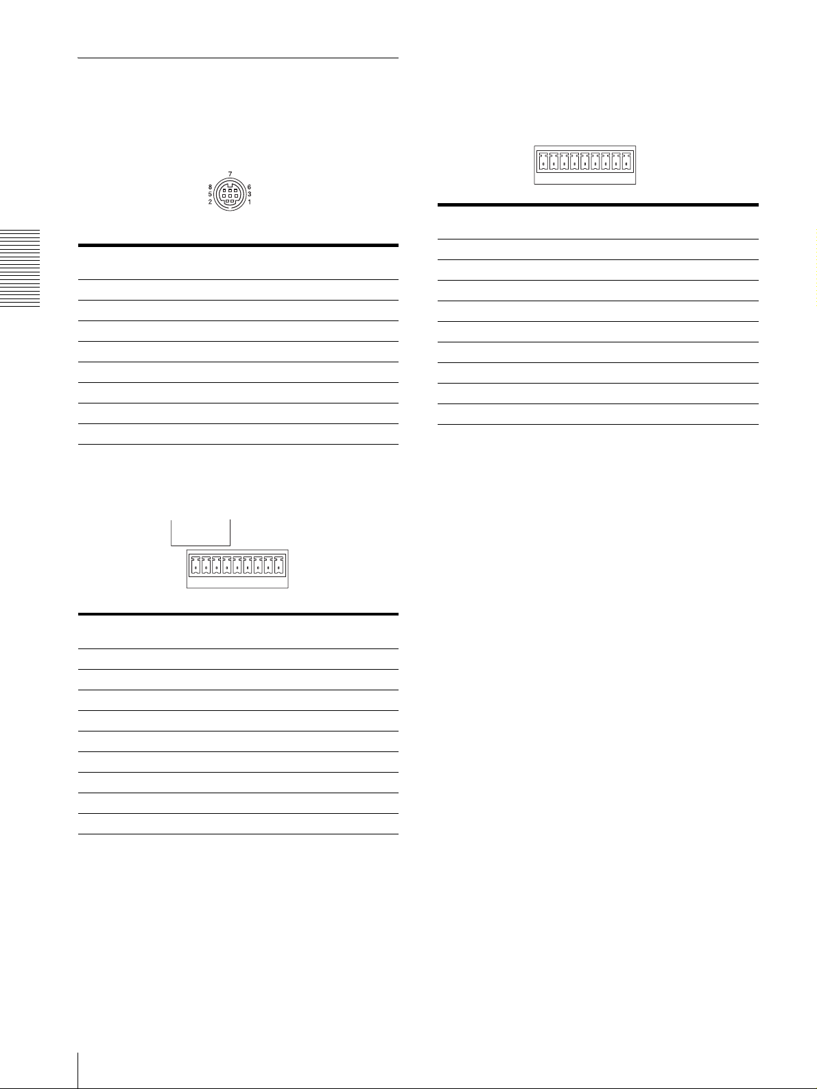
Asignaciones de terminales
Conector de salida VISCA RS-232C (mini-DIN
de 8 terminales, hembra)
Conector TALLY/CONTACT (clavija de conector,
9 terminales)
TALLY/CONTACT
RS-232C
Número de
terminal
Número de
terminal
1 Sin conexión
Apéndice
2 Sin conexión
3 TXD IN
4 GND
5 RXD IN
6 GND
7 Sin conexión
8 Sin conexión
Función
1 CAMERA1
2 CAMERA2
3 CAMERA3
4 CAMERA4
5 CAMERA5
6 CAMERA6
7 CAMERA7
8 GND
9 GND
19
Función
Conector VISCA RS-422 (clavija de conector,
9 terminales)
VISCA
RS-422
19
Número de
terminal
1 Sin conexión
2 Sin conexión
3 Sin conexión
4 Sin conexión
5 GND
6 RXD IN–
7 RXD IN+
8 TXD IN–
9 TXD IN+
Función
ES
18
Especificaciones
Page 55
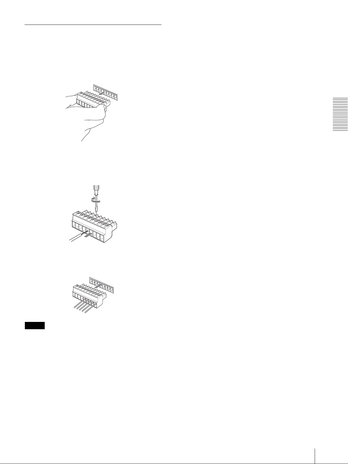
Uso de la clavija de conector VISCA
RS-422
1
Sujete ambos extremos de la clavija de conector
VISCA RS-422 y tire de ella como se muestra en la
ilustración.
1
9
2
Inserte un cable (Números AWG 28 a 18) en la
abertura de cable deseada de la clavija, y apriete el
tornillo de ese cable utilizando un destornillador de
cabeza plana.
Destornillador de cabeza
plana
Apéndice
Cable
3
Inserte la clavija de conector VISCA RS-422 en el
conector VISCA RS-422.
1
9
Notas
• Para estabilizar el nivel de tensión de la señal, conecte
ambos extremos a GND.
• Cuando se realicen las conexiones mediante los
conectores VISCA RS-422, el conector VISCA RS232C no estará disponible.
• La distancia máxima de conexión con el conector
VISCA RS-422 es aproximadamente de 1.200 m
(3.937 pies).
Especificaciones
19
ES
Page 56

WARNUNG
Um die Gefahr von Bränden oder
elektrischen Schlägen zu verringern, darf
dieses Produkt nicht Regen oder
Feuchtigkeit ausgesetzt werden.
Um einen elektrischen Schlag zu
vermeiden, darf das Gehäuse nicht
geöffnet werden. Überlassen Sie
Wartungsarbeiten nur qualifiziertem
Fachpersonal.
WARNUNG
Verwenden Sie das mit diesem Gerät gelieferte
Netzgerät Sony MPA-AC1 als Stromquelle. Andere
Stromquellen können Gefahren, wie z.B. einen Brand,
verursachen.
Um dieses Gerät vom Stromnetz zu trennen, muss der
Netzstecker des Netzgeräts abgezogen werden.
Der Netzstecker dieses Geräts muss zur Trennung von
der Netzstromquelle verwendet werden.
Bitte stellen Sie sicher, dass eine Netzsteckdose in der
Nähe des Geräts installiert und leicht zugänglich ist.
Ziehen Sie im Falle eines anormalen Betriebs den
Netzstecker ab.
WICHTIG
Das Typenschild befindet sich an der Unterseite.
ACHTUNG
Das bei bestimmten Frequenzen abgegebene
elektromagnetische Feld kann das Bild dieses Geräts
beeinflussen.
DE
2
Page 57

Inhaltsverzeichnis
Überblick
Merkmale ............................................................... 4
Vorsichtsmaßnahmen ............................................4
Lage und Funktion der Teile ................................ 5
Verfügbare Funktionen für Sony
VISCA-Kameras .............................................. 8
Anschlüsse und Bedienung
Anschlüsse .............................................................. 9
Anschluss einer Kamera mit
VISCA RS-232C-Buchse ................................. 9
Anschluss einer Kamera mit
VISCA RS-422-Buchse ................................. 10
Anschluss mehrerer Kameras mit
VISCA RS-232C-Buchse ............................... 10
Anschluss mehrerer Kameras mit
VISCA RS-422-Buchse ................................. 11
Anschluss der Optischen Multiplexeinheit
BRU-300/300P ...............................................12
Anschluss eines Videomischers ....................... 13
Einschalten ........................................................... 13
Speichern der Kameraeinstellungen
– Vorwahlfunktion ............................................... 14
Einstellen der Bewegungsgeschwindigkeit der
Kamera zu einer Vorwahlposition (nur BRC-300/
300P und BRC-H700/H700P) ........................ 15
DE
Anhang
Fehlerbehebung ...................................................16
Technische Daten .................................................17
Abmessungen ................................................... 17
Stiftbelegung .................................................... 18
Verwendung des VISCA RS-422-
Anschlusssteckers ........................................... 19
Inhaltsverzeichnis
DE
3
Page 58

Überblick
Vorsichtsmaßnahmen
Überblick
Merkmale
Der optische Dreiachsen-Joystick ermöglicht
bequeme Schwenk-/Neige-/Zoomoperationen.
Bequeme Bedienung vielseitiger
Kameraeinstellungen
Mit Hilfe der Tasten dieses Geräts können Sie
verschiedene Kameraeinstellungen, wie z.B. Autofokus,
Tastendruck-Autofokus, automatische
Belichtungseinstellung, Tastendruck-Weißabgleich und
Gegenlichtkompensation, durchführen.
Die VISCA RS-232C/RS-422-KommunikationsSchnittstellen ermöglichen schnelle
Kommunikation über große Entfernungen.
Das Gerät ist in der Lage, bis zu sieben Kameras in einer
Gerätekette zu steuern.
Ein Kamerakontrolllampen-Eingang/KontaktAusgang (9-poliger Anschlussstecker)
gestattet den Anschluss eines Videomischers.
Vorwahlfunktion zur Speicherung von
Kameraeinstellungen
Das Gerät ermöglicht die Speicherung von bis zu 16
Kameraeinstellungs-Kombinationen*, wie z.B.
Schwenk-/Neige-/Zoompositionen und andere
Kameraeinstellwerte, in der Kamera.
* Die Anzahl der speicherbaren Positionen hängt von
der angeschlossenen Kamera ab. (Für die 3-CCDFarbvideokamera BRC-300/300P können 6
Positionen gespeichert werden.)
Betrieb oder Lagerung des Geräts an folgenden Orten
kann eine Beschädigung des Geräts verursachen:
• Extrem heiße oder kalte Orte (Betriebstemperatur:
0
°C bis +40 °C)
• Orte, die längere Zeit direktem Sonnenlicht ausgesetzt
sind, oder in der Nähe einer Wärmequelle (z.B.
Heizkörper)
• Orte in der Nähe starker Magnetfelder
• Orte in der Nähe von Quellen starker
elektromagnetischer Strahlung, z.B. Radio- oder
Fernsehsender
• Orte, die starken Vibrationen oder Erschütterungen
ausgesetzt sind
Ventilation
Um einen Wärmestau zu verhüten, darf die
Luftzirkulation um das Gerät nicht blockiert werden.
Transport
Wenn Sie das Gerät transportieren wollen, verpacken
Sie es wieder in der Original-Werksverpackung oder in
Verpackungsmaterial der gleichen Qualität.
Reinigung
• Verwenden Sie ein weiches, trockenes Tuch zum
Reinigen der Außenflächen des Geräts. Entfernen Sie
hartnäckigen Schmutz, indem Sie ein weiches Tuch
mit etwas Reinigungslösung anfeuchten und
anschließend trocken wischen.
• Verwenden Sie keine leichtflüchtigen Lösungsmittel,
wie z.B. Alkohol, Benzin oder Verdünner, weil diese
die Lackschicht angreifen können.
Steuerbare Sony VISCA-Kameras
Das Gerät kann die folgenden Kameras steuern:
• BRC-300/300P 3CCD Color Video Camera
• BRC-H700/H700P HD 3CCD Color Video Camera
• EVI-D100/D100P Color Video Camera
• EVI-D70/D70P Color Video Camera
• EVI-D30/D30P Color Video Camera
• SNC-RZ30N/RZ30P Network Camera
Betriebs- oder Lagerungsort
Hinweise
• Die nutzbaren Funktionen hängen von der
Ausstattung der Kamera ab.
• Diese Anleitung erläutert hauptsächlich die
Funktionen der Einheit für die Kamera BRC-300/
300P.
Wenn eine andere Kamera angeschlossen wird,
schlagen Sie bezüglich der verfügbaren Funktionen in
der Bedienungsanleitung der angeschlossenen
Kamera nach.
DE
4
Merkmale / Vorsichtsmaßnahmen
Page 59
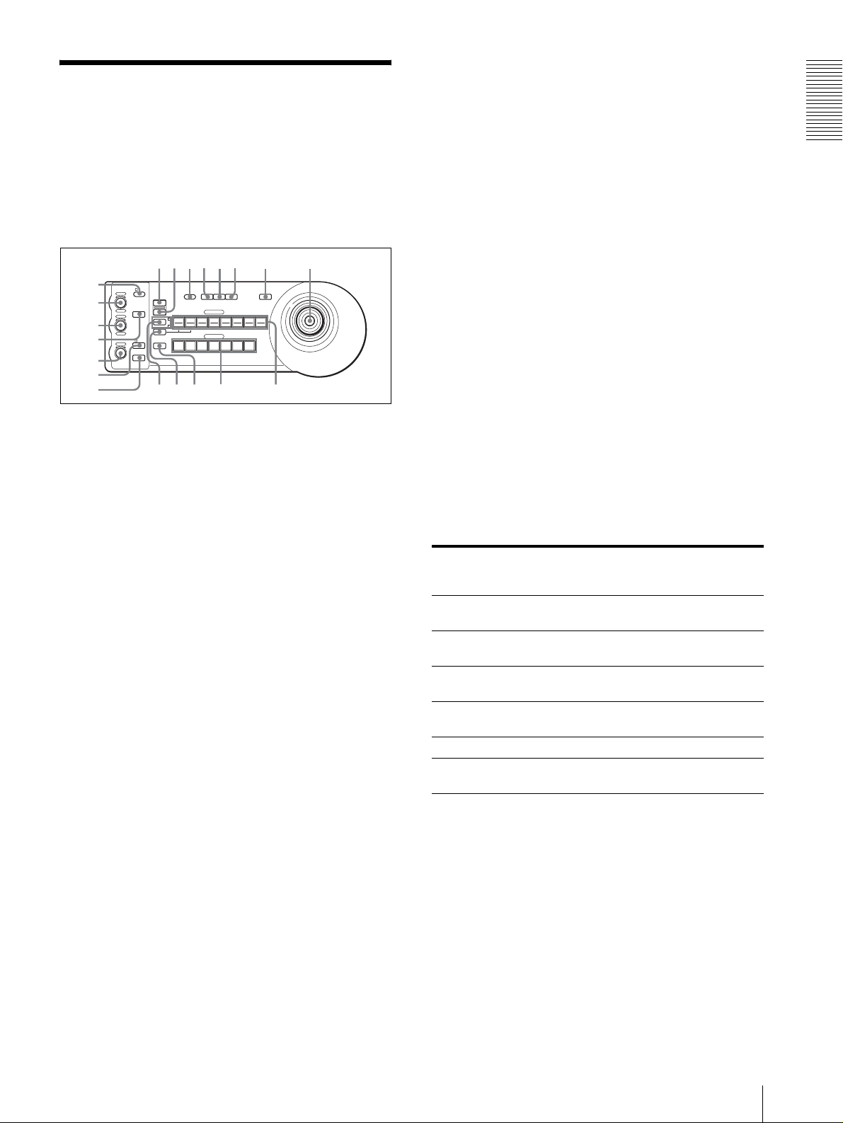
Lage und Funktion der
qhqjqkq
w
Teile
Diese Anleitung befasst sich mit den
Bedienungsvorgängen des Modells RM-BR300 bei
Verwendung mit der Kamera BRC-300/300P oder BRCH700/H700P.
Vorderse ite
90qaqsqd qf qg
8
1
VALUE
– +
BRIGHT
– +
NEAR FAR
LOCK
R
MODE
B
AUTO
FOCUS
AUTO
MANUAL
ONE PUSH
AF
2
3
4
5
6
7
A Taste und Anzeige LOCK
Wird die Taste LOCK länger als eine Sekunde
gedrückt, leuchtet die Lampe LOCK auf, und die
mit den Reglern VALUE/R, BRIGHT/B und
FOCUS eingestellten Werte werden verriegelt. (Die
Anzeigen der gesperrten Regler werden
ausgeschaltet.)
Die Taste AUTO/MANUAL wird ebenfalls deaktiviert.
Drücken Sie die Taste LOCK erneut länger als eine
Sekunde, um die Regler und Tasten wieder zu
aktivieren.
B Regler VALUE/R
Wenn der Helligkeitseinstellmodus mit der Taste
MODE gewählt wird (bei leuchtender Anzeige
VA L U E ) :
Dieser Regler dient zum Einstellen des Werts für
den an der Kamera gewählten Posten (SHUTTER
oder IRIS).
Wenn die Anzeige VALUE leuchtet, hängt die
Funktion des Reglers von dem an der Kamera
gewählten Belichtungsmodus ab. Einzelheiten
unter „Funktionen der Regler VALUE und
BRIGHT“ auf Seite 5.
Wenn der Weißabgleicheinstellmodus mit der
Taste MODE gewählt wird (bei leuchtender
Anzeige R):
Dieser Regler dient zum Einstellen des Werts für R.
GAIN (Rotverstärkung) (außer EVI-D30/D30P).
Wenn die Kamera BRC-H700/H700P
angeschlossen ist, hängt die Funktion des Reglers
bei leuchtender Anzeige R von dem an der Kamera
gewählten Weißabgleichmodus ab. Einzelheiten
unter „Funktionen der Regler R und B für die
Kamera BRC-H700/H700P“ auf Seite 5.
PRESET
DIRECTION
POWER
RESET
1
SHIFT
9
STD REV
L/R
1
PANEL
BLACK
PAN-TILT
ONE PUSH
LIGHT
LIGHT
RESET
AWB
POSITION
2
3114
5136147158
12
10
CAMERA
234567
l
MENU
16
;
C Regler BRIGHT/B
Wenn der Helligkeitseinstellmodus mit der Taste
MODE gewählt wird (bei leuchtender Anzeige
BRIGHT):
Dieser Regler dient zum Einstellen des
Helligkeitswerts der Kamera usw.
Wenn die Anzeige BRIGHT leuchtet, hängt die
Funktion des Reglers von dem an der Kamera
gewählten Belichtungsmodus ab. Einzelheiten
unter „Funktionen der Regler VALUE und
BRIGHT“ auf Seite 5.
Wenn der Weißabgleicheinstellmodus mit der
Taste MODE gewählt wird (bei leuchtender
Anzeige B):
Dieser Regler dient zum Einstellen des Werts für B.
GAIN (Blauverstärkung) (außer EVI-D30/D30P).
Wenn die Kamera BRC-H700/H700P
angeschlossen ist, hängt die Funktion des Reglers
bei leuchtender Anzeige B von dem an der Kamera
gewählten Weißabgleichmodus ab. Einzelheiten
unter „Funktionen der Regler R und B für die
Kamera BRC-H700/H700P“ auf Seite 5.
Funktionen der Regler VALUE und BRIGHT
Die Funktionen der Regler VALUE und BRIGHT
hängen von der Belichtungsmodus-Einstellung der
Kamera ab, wie folgt:
Belichtungsmodus der
Kamera
FULL AUTO Nicht benutzt Belichtungskor-
SHUTTER Pri Verschlusszeitregler Belichtungskor-
IRIS Pri Blendenregler Belichtungskor-
BRIGHT Nicht benutzt Helligkeitspegel-
MANUAL Verschlusszeitregler Blendenregler
GAIN Pri***
* Wenn die Belichtungskorrekturfunktion an der Kamera
aktiviert ist.
** Blenden- und Verstärkungsregelung ist für die Kamera
BRC-H700/H700P möglich.
*** Nur verfügbar für die Kamera BRC-H700/H700P
Funktion des
Reglers VALUE
Verstärkungsregelung***
Funktion des
Reglers BRIGHT
rekturpegelregler*
rekturpegelregler*
rekturpegelregler*
regler
**
Nicht benutzt
Funktionen der Regler R und B für die Kamera
BRC-H700/H700P
Wenn der Weißabgleicheinstellmodus mit der Taste
MODE dieser Einheit gewählt wird, ändern sich die
Funktionen des Reglers R und B gemäß der
Weißabgleichmodus-Einstellung an der Kamera BRCH700/H700P.
Überblick
DE
Lage und Funktion der Teile
5
Page 60

der Kamera, welcher der gedrückten Taste
Weißabgleichmodus an der
Kamera
MANUAL Rotverstärkungsre-
Überblick
AUTO, ONE
PUSH
Funktion des
Reglers R
gelung
Rot-WB SHIFTRegelung
Funktion des
Reglers B
Blauverstärkungsregelung
Blau-WB SHIFTRegelung
POSITION entspricht, gespeichert.
J Taste PANEL LIGHT
Drücken Sie diese Taste, um alle Tasten POSITION
und CAMERA zu beleuchten. Drücken Sie die
Taste erneut, um die Beleuchtung auszuschalten.
K Taste BACK LIGHT
Wenn der Belichtungsmodus FULL AUTO an der
D Tast e MO DE
Drücken Sie diese Taste, um die Funktion der
Regler VALUE/R und BRIGHT/B zu wählen.
Wenn der Helligkeitseinstellmodus gewählt wird,
Kamera aktiviert ist, drücken Sie diese Taste, um
die Gegenlichtkompensationsfunktion der Kamera
zu aktivieren. Drücken Sie die Taste erneut, um die
Funktion zu deaktivieren.
leuchten die Anzeigen VALUE und BRIGHT auf.
Wenn der Weißabgleicheinstellmodus gewählt
wird, leuchten die Anzeigen R und B auf.
E Regler FOCUS
Dieser Regler ist funktionsfähig, wenn MANUAL
mit der Taste AUTO/MANUAL gewählt wird.
Drehen Sie den Regler entgegen dem
Uhrzeigersinn (Richtung NEAR), um auf ein nahes
Objekt zu fokussieren, und im Uhrzeigersinn
(Richtung FAR), um auf ein entferntes Objekt zu
fokussieren.
F Taste AUTO/MANUAL und Anzeige AUTO
Drücken Sie diese Taste, um den Fokussiermodus
AUTO oder MANUAL zu wählen.
Bei Wahl von AUTO leuchtet die Anzeige AUTO
auf, und die Kamera fokussiert automatisch auf das
Objekt in der Mitte des Bildschirms. Der Regler
FOCUS und die Taste ONE PUSH AF sind
deaktiviert.
Bei Wahl von MANUAL ist der Regler FOCUS
und die Taste ONE PUSH AF aktiviert (bei
leuchtender Anzeige FOCUS).
G Tast e ON E PU SH AF
Diese Taste ist funktionsfähig, wenn MANUAL mit
der Taste AUTO/MANUAL gewählt wird. Drücken
Sie diese Taste, um die TastendruckAutofokusfunktion zu aktivieren (außer EVI-D30/
D30P).
Halten Sie im Falle der Kamera BRC-H700/H700P
die Taste SHIFT gedrückt, und drücken Sie diese
Taste, um die Scheinwerferkompensationsfunktion
der Kamera zu aktivieren. Diese Funktion stellt die
Belichtung auf eine dunklere Stufe ein, wenn ein
Teil des Aufnahmeobjekts beleuchtet ist. Um die
Scheinwerferkompensation zu deaktivieren, halten
Sie die Taste SHIFT gedrückt, und drücken Sie
diese Taste erneut.
L Taste PAN-TILT RESET
Drücken Sie diese Taste, um die Schwenk-/
Neigeposition der Kamera auf den
Ausgangszustand zurückzustellen.
M Tast e ON E PU SH AWB
Wenn der ONE PUSH-Weißabgleichmodus an der
Kamera aktiviert ist, kann durch Drücken dieser
Taste der Tastendruck-Weißabgleich durchgeführt
werden.
N Tast e ME NU
Drücken Sie diese Taste ungefähr eine Sekunde im
Falle der Kamera BRC-300/300P oder BRC-H700/
H700P, um das Kameramenü anzuzeigen, zum
Hauptmenü zurückzukehren, oder das Menü
abzuschalten.
Drücken Sie diese Taste ungefähr eine Sekunde bei
anderen Kameras, um die BildschirmDatenanzeige ein- und auszuschalten.
H Tast e RE SET
Wenn Sie eine der Tasten POSITION drücken,
während Sie diese Taste gedrückt halten, wird der
Speicher der Kamera, welcher der gedrückten Taste
POSITION entspricht, auf die Werksvorgabe
zurückgesetzt.
Wenn mehrere Kameras angeschlossen sind,
drücken Sie die Taste POWER, während Sie diese
Taste gedrückt halten, um die Kameraadressen
einzustellen.
I Taste PRESET
Wenn Sie eine der Tasten POSITION drücken,
während Sie diese Taste gedrückt halten, werden
die aktuellen Kameraeinstellungen in dem Speicher
DE
6
Lage und Funktion der Teile
O Joystick
Der Joystick wird für Schwenk-/Neige- und
Zoomoperationen verwendet. Wählen Sie die zu
steuernde Kamera mit Hilfe der Tasten CAMERA
aus, und betätigen Sie den Joystick.
Schwenken und Neigen
Wenn Sie den Joystick nach rechts und links
drücken, führt die Kamera einen Schwenk aus.
Wenn Sie ihn nach vorne oder hinten drücken, neigt
sich die Kamera.
Die Schwenk-/Neigegeschwindigkeit hängt vom
Betätigungswinkel ab.
Wenn Sie den Joystick loslassen, stoppt die
Kamerabewegung.
Page 61

Zoomen
wswdwfwgwhwjw
w
Wenn Sie den Knopf am oberen Ende des Joysticks
im Uhrzeigersinn drehen, wird der Bildausschnitt
vergrößert (Einzoomen). Wenn Sie ihn entgegen
dem Uhrzeigersinn drehen, wird der Bildausschnitt
verkleinert (Auszoomen).
So richten Sie die Kamera wieder
geradeaus
Wenn Sie die Taste am oberen Ende des Joysticks
bei ein- oder ausgeschaltetem Menü ein bis zwei
Sekunden lang drücken, wird die Schwenk-/
Neige-/Zoomposition zurückgestellt und die
Kamera geradeaus gerichtet.
P Taste und Anzeige SHIFT
Drücken Sie diese Taste länger als eine Sekunde,
um die Funktion der Tasten POSITION für die
Positionen 1 bis 8 bzw. 9 bis 16 zu wählen.
Die obere Anzeige leuchtet bei Wahl der Positionen
1 bis 8, und die untere Anzeige bei Wahl der
Positionen 9 bis 16 auf.
Halten Sie bei der Kamera BRC-H700/H700P die
Taste SHIFT gedrückt, und drücken Sie eine der
Tasten POSITION. Die untere Anzeige leuchtet
auf, und die Tasten POSITION können für die
Positionen 9 bis 16 benutzt werden. Wenn Sie die
Taste SHIFT loslassen, leuchtet die obere Anzeige
auf, und die Tasten POSITION können für die
Positionen 1 bis 8 benutzt werden.
Q Taste L/R DIRECTION
Die Kamera ist so voreingestellt, dass sie sich nach
rechts bewegt, wenn der Joystick nach rechts
geneigt wird. Drücken Sie die Taste POSITION 2
(REV), während Sie diese Taste gedrückt halten,
um die Schwenkrichtung auf die Richtung
umzukehren, in der Sie den Joystick drücken. Um
die Richtung zurückzustellen, drücken Sie die Taste
POSITION 1 (STD), während Sie diese Taste
gedrückt halten.
auszuwählen. Die gedrückte Taste CAMERA
leuchtet in Blau auf.
T Tast en P OSIT ION
Sie können verschiedene Kameraeinstellungen, wie
z.B. die Schwenk-, Neige- und Zoomposition, in
dem Speicher der Kamera ablegen, welcher der
jeweiligen Taste POSITION entspricht, und die
gespeicherten Einstellungen laden.
Funktionen der Tasten POSITION für die
Kameras EVI-D100/D100P und EVI-D70/
D70P
Wenn eine der Kameras EVI-D100/D100P oder EVID70/D70P an diese Einheit angeschlossen wird, erkennt
die Einheit automatisch das Kameramodell, und die
Funktionen der Positionen 7 bis 16 der Tasten
POSITION ändern sich gemäß der nachstehenden
Tabelle. Dies gestattet Ihnen die direkte Steuerung der
Kamera ohne Anschluss an einen Computer.
Tas t e PO SITION Funktion
Position 7 Automatische Belichtung
–Modus Full Auto
Position 8 Automatische Belichtung
– Modus Bright
Position 9 Digitalzoom – EIN
Position 10 Digitalzoom – AUS
Position 11 Automatischer Weißabgleichmodus
Position 12 Manualler Weißabgleichmodus
Position 13 ONE PUSH-Weißabgleichmodus
Position 14 Weißabgleich-Nachregelautomatikmodus
(ATW)
Position 15 IR Cut-Removable (ICR) – EIN
Position 16 IR Cut-Removable (ICR) – AUS
Einzelheiten zu jeder Funktion finden Sie im TechnikHandbuch der Kamera.
Überblick
R Taste POWER
Drücken Sie diese Taste, um die Tasten CAMERA,
die dem Status der angeschlossenen Kameras
entsprechen, zum Aufleuchten zu bringen.
Blau: Die Stromversorgung der Kamera ist
eingeschaltet.
Gelbgrün: Die Kamera befindet sich im
Bereitschaftsmodus.
Aus: Es ist keine Kamera angeschlossen.
Drücken Sie die Tasten CAMERA 1 bis 7, während
Sie diese Taste gedrückt halten, um die
Stromversorgung der Kamera, die der gedrückten
Taste entspricht, ein- und auszuschalten.
S Tasten CAMERA
Drücken Sie eine der Tasten, um die gewünschte
Kamera unter den angeschlossenen Kameras
Rückseite/Unterseite
MODE
RS-232C
a
RS-422 ON/OFF
VISCA
1919
TALLY/CONTACT
CONTACT(TALLY)
TALLY
CONTACT DC IN 12V
!
U Wahlschalter MODE
Damit wählen Sie die Position, die der
anzuschließenden VISCA-steuerbaren Kamera
entspricht.
Lage und Funktion der Teile
k
DE
7
Page 62

Y Wahlschalter TALLY/CONTACT
Schalterstellung Kamera-Modus
0 Automatisch gewählt (Vorgabe)
1 BRC-300/300P
Überblick
2 EVI-D70/D70P
3 EVI-D100/D100P
4 EVI-D30/D30P
5SNC-RZ30N/RZ30P
6 BRC-H700/H700P
Hinweise
• Verwenden Sie die Positionen 1 bis 4, wenn alle
angeschlossenen Kameras vom gleichen Modell
sind.
• Verwenden Sie Position 5 für das Modell SNCRZ30N/RZ30P.
V Buchse VISCA RS-232C
Verbinden Sie diese Buchse mit der Buchse VISCA
RS-232C IN der Kamera oder der Optischen
Multiplexeinheit.
W Buchse VISCA RS-422
Verbinden Sie diese Buchse mit der Buchse VISCA
RS-422 der Kamera oder der Optischen
Multiplexeinheit.
Ein RS-422-Anschlussstecker wurde werksseitig
Damit wählen Sie die Funktion der Buchse
TALLY/CONTACT.
TAL LY: Die Kamerakontrolllampe der mit dem
angeschlossenen Mischer gewählten Kamera
leuchtet auf.
CONTACT: Der Kontakt-Ausgang, welcher der
mit dieser Fernbedienungseinheit gewählten
Kameraadresse entspricht, wird gegen den
angeschlossenen Mischer kurzgeschlossen.
CONTACT (TALLY): Der Kontakt-Ausgang,
welcher der mit dieser Fernbedienungseinheit
gewählten Kameraadresse entspricht, wird gegen
den angeschlossenen Mischer kurzgeschlossen,
und die Kamerakontrolllampe der mit dem
angeschlossenen Mischer gewählten Kamera
leuchtet auf.
wh Buchse DC IN 12V
Dient zum Anschluss des mitgelieferten
Netzgeräts.
wj DIP-Schalter (Unterseite)
Schalter 1 (RS-232C/RS-422-Wahlschalter)
Stellen Sie diesen Schalter für RS-422 auf ON bzw.
für RS-232C auf OFF.
Schalter 2 (Übertragungs-BaudratenWahlschalter)
Stellen Sie diesen Schalter für 38.400 bps auf ON
bzw. für 9.600 bps auf OFF.
angebracht.
X Buchse TALLY/CONTACT
Diese Buchse wird als Kamerakontrolllampen-
wk Schalter ON/OFF
Drücken Sie diesen Schalter, um das Gerät ein- und
auszuschalten.
Eingang oder Kontakt-Ausgang verwendet.
Wählen Sie die Funktion der Buchse mit dem
Wahlschalter TALLY/CONTACT.
Ein RS-422-Anschlussstecker wurde werksseitig
angebracht.
Hinweis
Stellen Sie die Schalter ein, bevor Sie dieses Gerät
einschalten. Anderenfalls ist die Einstellung nicht
wirksam.
Verfügbare Funktionen für Sony VISCA-Kameras
Die Funktionen der Regler, Tasten und Buchsen in der folgenden Liste hängen vom angeschlossenen Kameramodell ab.
Die Funktionen der übrigen Teile sind für alle Kameramodelle gleich.
Teile BRC-300/
B Regler VALUE/R a a a
C Regler BRIGHT/B a a a
G Taste ONE PUSH AF a a a
L Taste PAN-TILT RESET a a a a
N Taste M E N U a a a a
R Taste P OWER a a a a
S Tasten CAMERA a a a a
W Buchse VISCA RS-422 a
a: verfügbar, ×: nicht verfügbar
DE
8
Lage und Funktion der Teile
300P, BRC-
H700/H700P
EVI-D100/
D100P
×
EVI-D70/
D70P
a
EVI-D30/
D30P
×
×
×
× ×
SNC-RZ30N/
RZ30P
a
a
a
×
×
×
×
Page 63

Anschlüsse und Bedienung
Anschlüsse
Dieser Abschnitt befasst sich mit den
Anschlussbeispielen für die Kamera BRC-300/300P.
Informationen zum Anschluss anderer Kameras
entnehmen Sie bitte der Bedienungsanleitung der
anzuschließenden Kamera.
Anschluss einer Kamera mit VISCA
RS-232C-Buchse
1
Schließen Sie dieses Gerät über das mitgelieferte
RS-232C-Verbindungskabel an die Kamera an.
2
Schließen Sie dieses Gerät über das mitgelieferte
Netzgerät und das Netzkabel an eine Netzsteckdose
an.
Hinweis
Wenn Sie die VISCA RS-232C-Buchsen verwenden
wollen, vergewissern Sie sich, dass der DIP-Schalter an
der Unterseite dieses Geräts (Seite 8) auf RS-232C
eingestellt ist.
Verbindungskabel
Verwenden Sie das folgende Verbindungskabel zum
Anschluss von Geräten in diesem System.
Kabel Teile-Nr. Anzahl
RS-232C-Kabel
(3 m)
RS-232C-Kabel
1-590-879-3X 1
Anschlüsse und Bedienung
OFF ON
EXT SYNC IN
IR SELECT
75
VIDEO S VIDEO
1 2 3
R
1 2 3 4 5 6 7 8 9
VISCA RS-422
!
IN VISCA RS-232C OUT
DC IN
12V
VISCA RS-232C IN
RS-232C-Kabel (mitgeliefert)
(SONY: 1-590-879-3X)
VISCA RS-232C
DC IN 12V
Kamera BRC-300/300P
an eine
Netzsteckdose
Netzkabel
(mitgeliefert)
Netzgerät MPA-AC1
(mitgeliefert)
an eine
Netzsteckdose
Anschlüsse
DE
9
Page 64
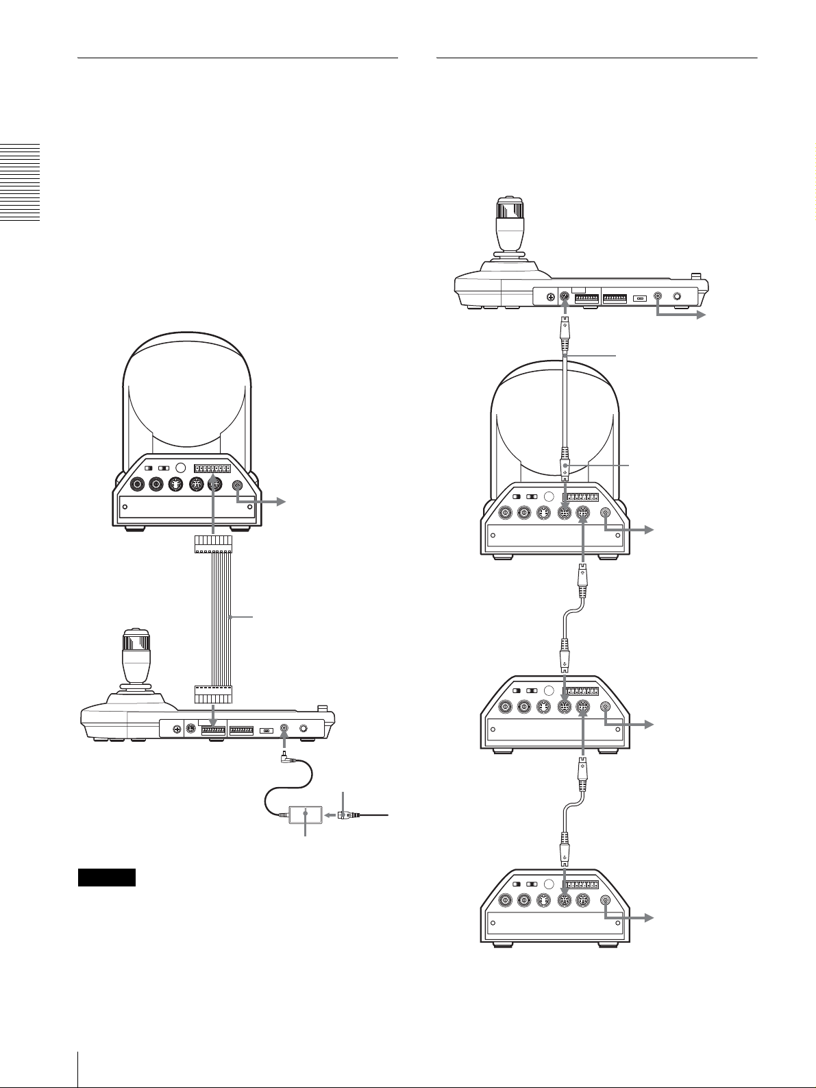
Anschluss einer Kamera mit VISCA
Anschluss mehrerer Kameras mit
RS-422-Buchse
Anstelle der VISCA RS-232C-Buchsen können Sie
auch die VISCA RS-422-Buchsen verwenden, um die
Fernbedienungseinheit mit der Kamera zu verbinden.
Die VISCA RS-422-Buchsen gestatten eine Verbindung
VISCA RS-232C-Buchse
Verbindungen mit den VISCA RS-232C-Kabeln
(Kreuzkabel) ermöglichen die Steuerung von bis zu
sieben Kameras mit einer einzigen
Fernbedienungseinheit RM-BR300.
bis zu einer Entfernung von 1.200 m.
Stecken Sie die mit diesem Gerät gelieferten RS-422Anschlussstecker auf das Verbindungskabel.
Anschlüsse und Bedienung
Nehmen Sie zur Anfertigung des Kabels auf die
Stiftbelegung der VISCA RS-422-Buchse Bezug
(Seite 18).
Angaben zum Gebrauch der RS-422-Anschlussstecker
finden Sie auf Seite 19.
Kamera BRC-300/300P
an eine
Netzsteckdose
VISCA RS-422
VISCA RS-232C
Kamera BRC300/300P
EXT SYNC IN
OFF ON
75
1 2 3
IR SELECT
VIDEO S VIDEO
R
1 2 3 4 5 6 7 8 9
IN VISCA RS-232C OUT
VISCA RS-422
RS-232C-Kabel
(mitgeliefert)
(SONY: 1-590-879-3X)
an VISCA RS-232C IN
!
DC IN
12V
an eine
Netzsteckdose
an eine
Netzsteckdose
VISCA RS-422-Kabel
VISCA RS-422
DC IN 12V
Netzkabel
(mitgeliefert)
an eine
Netzgerät MPA-AC1
Netzsteckdose
(mitgeliefert)
Hinweise
• Wenn Sie die VISCA RS-422-Buchsen verwenden
wollen, vergewissern Sie sich, dass der DIP-Schalter
an der Unterseite dieses Geräts (Seite 8) auf RS-422
eingestellt ist.
• Wenn die Verbindung über die VISCA RS-422-
Buchsen hergestellt wird, ist die VISCA RS-232CVerbindung nicht verfügbar.
Erste Kamera
RS-232C-Kabel
VISCA RS-232C IN
R
1 2 3 4 5 6 7 8 9
1 2 3
OFF ON
IR SELECT
EXT SYNC IN
75
VIDEO S VIDEO
VISCA RS-422
IN VISCA RS-232C OUT
Zweite Kamera
RS-232C-Kabel
VISCA RS-232C IN
R
1 2 3 4 5 6 7 8 9
1 2 3
OFF ON
IR SELECT
EXT SYNC IN
75
VIDEO S VIDEO
VISCA RS-422
IN VISCA RS-232C OUT
Dritte bis siebte Kamera
VISCA RS-232C OUT
!
DC IN
12V
an eine
Netzsteckdose
VISCA RS-232C OUT
!
DC IN
12V
an eine
Netzsteckdose
DE
10
Anschlüsse
Page 65

Hinweis
Hinweise
Wenn Sie die VISCA RS-232C-Buchsen verwenden
wollen, vergewissern Sie sich, dass der DIP-Schalter an
der Unterseite dieses Geräts (Seite 8) auf RS-232C
eingestellt ist.
So weisen Sie die Kameraadressen zu
Bevor Sie mit der Bedienung beginnen können, müssen
Sie die Kameraadressen den angeschlossenen Kameras
zuweisen. Dann können Sie durch einfaches Drücken
der entsprechenden Taste CAMERA die zu bedienende
Kamera anwählen.
1
Schalten Sie alle angeschlossenen Kameras und
dieses Gerät ein.
2
Drücken Sie die Taste POWER an diesem Gerät,
während Sie die Taste RESET gedrückt halten.
Das Gerät erkennt die angeschlossenen Kameras
und weist ihnen automatisch die Kameraadressen 1
bis 7 in der angeschlossenen Reihenfolge zu.
3
Drücken Sie die Taste POWER an diesem Gerät,
und vergewissern Sie sich, dass die Tasten
CAMERA aufleuchten.
Anhand der Anzahl der leuchtenden Tasten
CAMERA kann festgestellt werden, wie vielen
Kameras Adressen zugewiesen worden sind.
Nun können Sie durch Drücken der entsprechenden
Taste CAMERA auf die zu steuernde Kamera
umschalten.
• Wenn Sie die VISCA RS-422-Buchsen verwenden
wollen, vergewissern Sie sich, dass der DIP-Schalter
an der Unterseite dieses Geräts (Seite 8) auf RS-422
eingestellt ist.
• Wenn die Verbindung über die VISCA RS-422Buchsen hergestellt wird, ist die VISCA RS-232CVerbindung nicht verfügbar.
VISCA RS-422
Kamera BRC300/300P
Erste Kamera
OFF ON
EXT SYNC IN
IR SELECT
75
VIDEO S VIDEO
1 2 3
R
IN VISCA RS-232C OUT
1 2 3 4 5 6 7 8 9
VISCA RS-422
an eine Netzsteckdose
VISCA RS-422-Kabel
an VISCA RS-422
!
DC IN
12V
an eine
Netzsteckdose
VISCA RS-422
Anschlüsse und Bedienung
Anschluss mehrerer Kameras mit
VISCA RS-422-Buchse
Der Anschluss über die VISCA RS-422-Buchsen
ermöglicht die Steuerung mehrerer Kameras. Dabei
kann das Verbindungskabel bis zu 1.200 m lang sein.
Stecken Sie die mit diesem Gerät gelieferten RS-422Anschlussstecker auf das Verbindungskabel.
Nehmen Sie zur Anfertigung des Kabels auf die
Stiftbelegung der VISCA RS-422-Buchse Bezug
(Seite 18).
Angaben zum Gebrauch der RS-422-Anschlussstecker
finden Sie auf Seite 19.
Der Stromlaufplan der VISCA RS-422-Verbindung ist
in der Bedienungsanleitung der Kamera BRC-300/300P
enthalten.
R
1 2 3 4 5 6 7 8 9
1 2 3
OFF ON
IR SELECT
EXT SYNC IN
75
VIDEO S VIDEO
VISCA RS-422
IN VISCA RS-232C OUT
Zweite Kamera
R
1 2 3 4 5 6 7 8 9
1 2 3
OFF ON
IR SELECT
EXT SYNC IN
75
VIDEO S VIDEO
VISCA RS-422
IN VISCA RS-232C OUT
Dritte bis siebte Kamera
VISCA RS-422-Kabel
VISCA RS-422
!
DC IN
12V
an eine
Netzsteckdose
VISCA RS-422
VISCA RS-422-Kabel
VISCA RS-422
!
DC IN
12V
an eine
Netzsteckdose
Anschlüsse
11
DE
Page 66
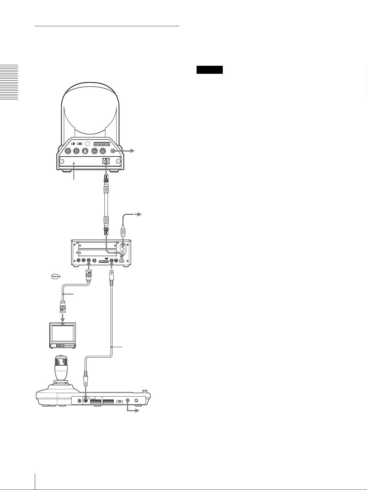
Anschluss der Optischen
Multiplexeinheit BRU-300/300P
Die Kamera kann über die Optische Multiplexeinheit
BRU-300/300P (nicht mitgeliefert) mit diesem Gerät
gesteuert werden.
Im Falle der Kamera BRC-H700/H700P können Sie die
Optische Multiplexeinheit BRU-H700/H700P benutzen,
um die Kamera mit dieser Einheit zu steuern.
Einzelheiten zum Anschluss entnehmen Sie bitte der
Bedienungsanleitung der Kamera BRC-H700/H700P.
Hinweis
Wenn Sie die VISCA RS-232C- oder die VISCA RS422-Buchsen verwenden wollen, vergewissern Sie sich,
Kamera BRC-300/300P
Anschlüsse und Bedienung
dass der Schalter VISCA FUNCTION an der Rückseite
der Optischen Multiplexeinheit und der DIP-Schalter an
der Unterseite dieses Geräts (Seite 8) korrekt auf RS232C bzw. RS-422 eingestellt sind.
R
1 2 3 4 5 6 7 8 9
1 2 3
OFF ON
IR SELECT
EXT SYNC IN
75
VIDEO S VIDEO
VISCA RS-422
IN VISCA RS-232C OUT
!
DC IN
12V
an eine
Netzsteckdose
Optische Multiplexkarte
BRBK-303
CAMERA
T VIDEO
(oder S VIDEO)
75-OhmKoaxialkabel
(oder S-VideoKabel)
Videomonitor usw.
Lichtleiterkabel
CCFC-M100
an eine
Netzsteckdose
Netzkabel (mit
BRU-300/300P
geliefert)
Optische
Multiplexeinheit
BRU-300/300P
VISCA RS-232C IN
RS-232C-Kabel
(mitgeliefert)*
(SONY: 1-590-879-3X)
DE
VISCA RS-232C
* Bei Verwendung der VISCA RS-422-Buchsen ist auch die
VISCA RS-422-Verbindung verfügbar.
12
Anschlüsse
an eine
Netzsteckdose
Page 67

Anschluss eines Videomischers
Verwenden Sie einen im Fachhandel erhältlichen
Videomischer mit Kontaktsteuerung, um zwischen den
auszugebenden Kamerasignalen umzuschalten.
Einschalten
Dritte bis siebte
Kamera
T VIDEO
Zweite Kamera
T VIDEO
75-Ohm-Koaxialkabel*
Erste Kamera
75-Ohm-Koaxialkabel*
EXT SYNC IN
EXT SYNC IN
EXT SYNC IN
OFF ON
OFF ON
OFF ON
75
75
75
R
1 2 3 4 5 6 7 8 9
1 2 3
IR SELECT
VISCA RS-422
IN VISCA RS-232C OUT
VIDEO S VIDEO
VISCA RS-232C IN
R
1 2 3 4 5 6 7 8 9
1 2 3
IR SELECT
VISCA RS-422
IN VISCA RS-232C OUT
VIDEO S VIDEO
VISCA RS-232C IN
R
1 2 3 4 5 6 7 8 9
1 2 3
IR SELECT
VISCA RS-422
IN VISCA RS-232C OUT
VIDEO S VIDEO
VISCA RS-232C IN
Kamera
BRC-300/300P
!
DC IN
12V
an eine
Netzsteckdose
RS-232C-Kabel
VISCA RS-232C OUT
!
DC IN
12V
RS-232C-Kabel
VISCA RS-232C OUT
!
DC IN
12V
1 2
VALUE
– +
R
BRIGHT
– +
B
FOCUS
NEAR FAR
LOCK
MODE
AUTO
AUTO
MANUAL
ONE PUSH
AF
RESET
RESET
PRESET
SHIFT
L/R
DIRECTION
POWER
PANEL LIGHT
PANEL
BLACK
PAN-TILT
LIGHT
LIGHT
RESET
POSITION
2
3114
1
9
10
12
STD REV
CAMERA
1
234567
ONE PUSH
AWB
5136147158
MENU
16
POWER CAMERA
1
Schließen Sie die Kamera an eine Netzsteckdose
an.
Die Stromversorgung der Kamera wird
eingeschaltet, und die Lampe POWER leuchtet auf.
Die Kamera führt automatisch eine Schwenk- und
Neigebewegung aus und stellt sich auf die in
POSITION 1 gespeicherte Position zurück
(Schwenk-/Neigerückstellung).
2
Schalten Sie dieses Gerät durch Drücken des
Schalters ON/OFF ein.
Die Taste CAMERA, die der zuletzt
ausgeschalteten Kamera entspricht, leuchtet auf.
(Die Taste CAMERA 1 leuchtet standardmäßig
auf.)
Anschlüsse und Bedienung
RS-232C-Kabel
(mitgeliefert)
(SONY: 1-590-879-3X)
VISCA RS-232C
MODE
RS-232C
VISCA
1919
CONTACT(TALLY)
RS-422 ON/OFF
TALLY/CO NTA CT
!
TALLY
CONTACT DC IN 12V
TALLY/CONTACT
an FBAS-Video-Eingang
75-Ohm-Koaxialkabel*
an
Kontaktsteuerklemme
Videomischer (im Handel erhältlich)
* Sie können auch die Buchse S VIDEO der Kamera über ein
S-Video-Kabel mit der S-Video-Eingangsbuchse des
Videomischers verbinden.
Weitere Einzelheiten über den Anschluss an einen
Videomischer entnehmen Sie bitte der
Bedienungsanleitung des Mischers.
3
Schalten Sie die Peripheriegeräte ein.
Hinweise
• Schalten Sie die Kamera unbedingt vor diesem Gerät
ein. Anderenfalls kann das Gerät die angeschlossene
Kamera nicht erkennen.
• Berühren Sie nicht den Joystick, wenn Sie das Gerät
einschalten. Anderenfalls kann die Bestätigung des
Nullpunkts beeinflusst werden.
So schalten Sie die Kamera mit diesem
Gerät ein und aus
Solange die Kamera an eine Netzsteckdose
angeschlossen ist, kann sie mit der Taste POWER dieses
Geräts ein- und ausgeschaltet werden.
Während Sie die Taste POWER gedrückt halten,
drücken Sie die Taste CAMERA, die der ein-/
auszuschaltenden Kamera entspricht.
Wird die Kamera mit diesem Gerät ausgeschaltet,
erlischt die Lampe POWER, und die Lampe STANDBY
an der Kamera leuchtet auf.
Einschalten
13
DE
Page 68
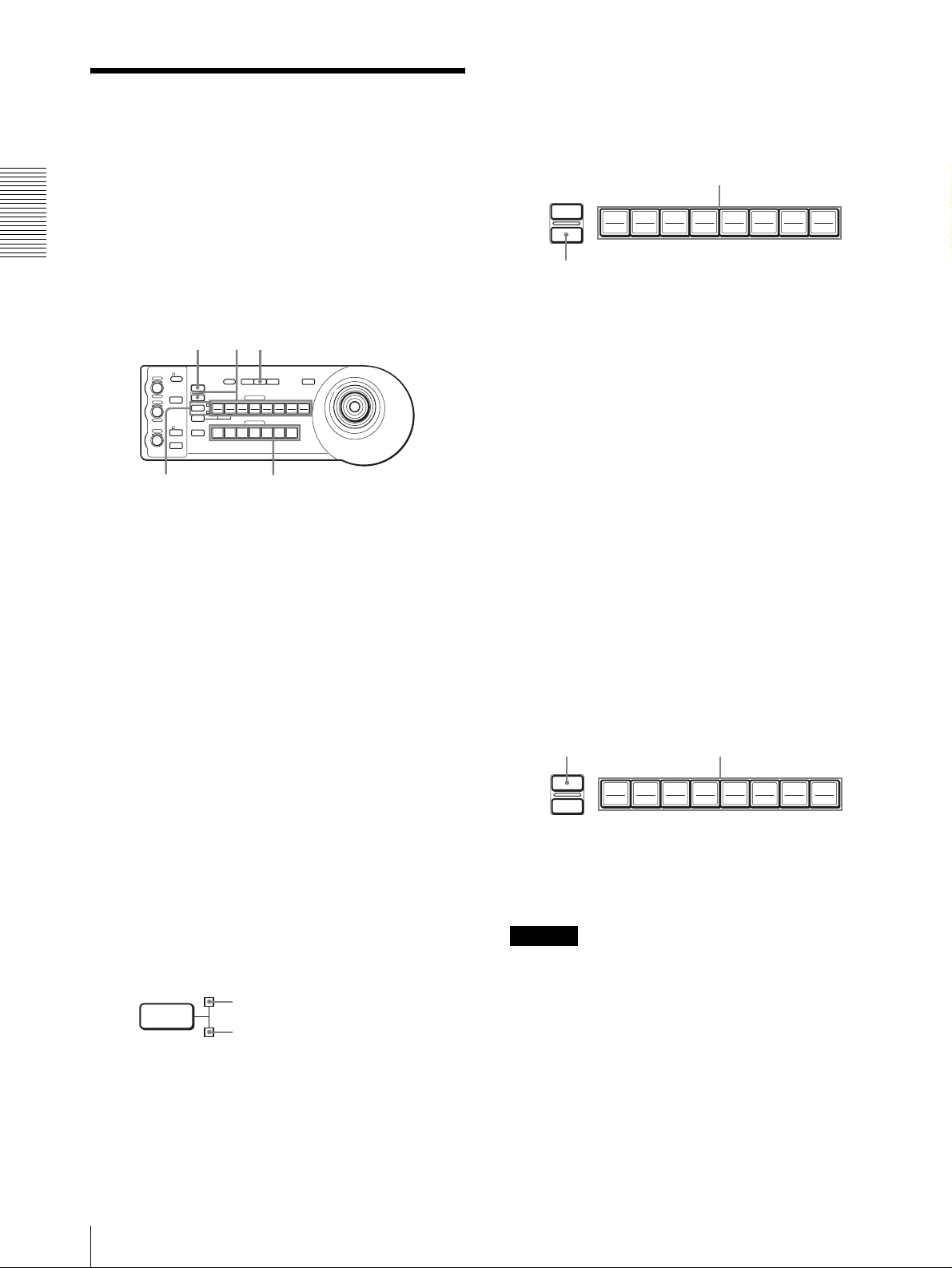
Speichern der
Kameraeinstellungen
5
Während Sie die Taste PRESET gedrückt halten,
drücken Sie eine der Tasten POSITION 1 bis 8,
unter der Sie die Einstellungen speichern wollen.
(außer BRC-H700/H700P)
– Vorwahlfunktion
Bis zu sechzehn Einstellungskombinationen (sechzehn
Positionen), einschließlich Kameraposition,
Anschlüsse und Bedienung
Zoomeinstellung, Fokuseinstellung und
Gegenlichtkompensation, können mit Hilfe dieses
RESET
PRESET
Bei gedrückt gehaltener Taste
Drücken Sie eine Taste POSITION.
192103114125136147158
16
Geräts im Speicher der Kamera abgelegt werden.
Die Einstellungen werden im Speicher der Kamera
RESET
51
abgelegt.
Die gedrückte Taste blinkt während des
– +
– +
NEAR FAR
VALUE
LOCK
R
MODE
BRIGHT
B
AUTO
FOCUS
AUTO
MANUAL
ONE PUSH
AF
RESET
PRESET
1
SHIFT
9
STD REV
L/R
DIRECTION
POWER
1
PANEL
BLACK
PAN-TILT
ONE PUSH
LIGHT
LIGHT
RESET
AWB
POSITION
2
3114
5136147158
10
12
CAMERA
234567
MENU
16
Speichervorgangs. Wenn der Speichervorgang
beendet ist, hört das Blinken auf.
So rufen Sie die gespeicherte Einstellung
ab
24
1
Drücken Sie die Taste PAN-TILT RESET, um die
Schwenk-/Neigeposition zurückzustellen.
2
Drücken Sie die Taste CAMERA zur Wahl der
Kamera, deren Einstellungen Sie vorwählen
wollen.
3
Stellen Sie die Position, Zoomeinstellung,
Fokuseinstellung und Gegenlichtkompensation der
Kamera ein.
4
Drücken Sie gegebenenfalls die Taste SHIFT
länger als eine Sekunde, um die Funktion der
Tasten POSITION 1 bis 8 zu wählen. (außer BRCH700/H700P)
Um die Positionen 1 bis 8 zu belegen, drücken Sie
die Taste SHIFT, so dass die obere Anzeige
aufleuchtet. Die Tasten POSITION 1 bis 8 können
für die Positionen 1 bis 8 verwendet werden.
Um die Positionen 9 bis 16 zu belegen, drücken Sie
die Taste SHIFT, so dass die untere Anzeige
aufleuchtet. Die Tasten POSITION 1 bis 8 können
für die Positionen 9 bis 16 verwendet werden.
SHIFT
für Positionen 1 bis 8
für Positionen 9 bis 16
Wählen Sie gegebenenfalls die Funktion der Tasten
POSITION 1 bis 8, indem Sie die Taste SHIFT länger
als eine Sekunde drücken. Drücken Sie eine der Tasten
POSITION 1 bis 8, unter der Sie die Einstellungen
gespeichert haben.
So löschen Sie einen Vorwahlspeicher
Wählen Sie gegebenenfalls die Funktion der Tasten
POSITION 1 bis 8 mit der Taste SHIFT. Während Sie
die Taste RESET gedrückt halten, drücken Sie die Taste
POSITION, deren Einstellungen Sie löschen wollen.
Bei gedrückt gehaltener Taste
RESET
PRESET
192103114125136147158
Die gedrückte Taste blinkt während der Löschung der
Einstellungen. Das Blinken hört auf, wenn die
Einstellungen gelöscht worden sind.
Hinweise
• Wenn die Kamera eingeschaltet wird, ruft sie die in
POSITION 1 gespeicherten Einstellungen ab.
• Sollen die vorherigen Schwenk-/Neigepositionen
auch nach dem Aus- und Einschalten erhalten bleiben,
speichern Sie diese Positionen unter POSITION 1 ab.
• Wenn Sie die Einstellungen einer POSITION
speichern oder löschen, können Sie die Einstellungen
einer anderen POSITION nicht abrufen, speichern
oder löschen.
Drücken Sie eine Taste
POSITION.
16
DE
14
Speichern der Kameraeinstellungen – Vorwahlfunktion
Page 69

So wählen Sie die Positionen 9 bis 16 für
BRC-H700/H700P
Während Sie die Taste SHIFT gedrückt halten, drücken
Sie die Taste PRESET (um die Einstellungen zu
speichern oder abzurufen) oder die Taste RESET (um
die Einstellungen aufzuheben). Die untere Anzeige
leuchtet auf, und die Tasten POSITION 1 bis 8 können
für die Positionen 9 bis 16 verwendet werden.
Wenn Sie die Taste SHIFT loslassen, leuchtet die obere
Anzeige auf, und die Tasten POSITION 1 bis 8 können
für die Positionen 1 bis 8 benutzt werden.
Im Falle der BRC-H700/H700P brauchen Sie die Taste
SHIFT nicht länger als eine Sekunde zu drücken, um die
Anzeige im Voraus umzuschalten.
Einstellen der
Bewegungsgeschwindigkeit der
Kamera
zu einer Vorwahlposition
(nur BRC-300/300P und BRC-H700/
H700P)
Sie können die Schwenk-/Neigegeschwindigkeit der
Kamera wählen, wenn sie sich zu einer Vorwahlposition
bewegt.
1
Drücken Sie die Taste CAMERA zur Wahl der
Kamera, deren Geschwindigkeit Sie einstellen
wollen.
2
Halten Sie die Taste POSITION, für die Sie die
Geschwindigkeit einstellen wollen, länger als eine
Sekunde gedrückt.
Alle Tasten CAMERA, 1 bis 7, blinken.
3
Drücken Sie eine der Tasten CAMERA zur Wahl
der Geschwindigkeit.
Anschlüsse und Bedienung
Taste CAMERA Schwenk-/
11°/Sek.
22,2°/Sek.
34,8°/Sek.
411°/Sek.
5 23,3°/Sek.
643°/Sek.
7 60°/Sek. (Vorgabe)
Nun bewegt sich die Kamera mit der gewählten
Geschwindigkeit zu der unter der Taste POSITION
gespeicherten Position.
Neigegeschwindigkeit
So stellen Sie die Geschwindigkeit der
Kamerabewegung zu einer
Vorwahlposition für BRC-H700/H700P ein
Um die Geschwindigkeit der Kamerabewegung zu einer
Vorwahlposition zwischen 9 und 16 einzustellen, halten
Sie die Taste SHIFT gedrückt, und drücken Sie die
entsprechende Taste POSITION.
Speichern der Kameraeinstellungen – Vorwahlfunktion
15
DE
Page 70

Anhang
Fehlerbehebung
Bevor Sie Ihr Gerät in Reparatur geben, überprüfen Sie
die folgenden Punkte als Leitfaden zur Behebung des
Problems. Falls sich das Problem nicht beheben lässt,
wenden Sie sich an Ihren Sony-Händler.
Symptom Ursache Abhilfemaßnahme
Das Gerät lässt sich nicht einschalten. Das Netzgerät ist nicht einwandfrei an die
Anhang
Die Kamera lässt sich nicht mit dem
Gerät bedienen.
Das Gerät lässt sich überhaupt nicht
bedienen. —
Buchse DC IN 12V angeschlossen.
Das Netzkabel ist nicht fest an das Netzgerät
oder die Netzsteckdose angeschlossen.
Der Anschluss an die VISCA RS-422-
Buchsen wurde nicht korrekt ausgeführt.
Die VISCA-Steuereinstellung ist nicht
korrekt.
Die Einstellungen der KommunikationsBaudrate an Kamera und Gerät stimmen nicht
überein.
Führen Sie das Stromversorgungskabel fest
bis zum Anschlag ein.
Führen Sie das Stromversorgungskabel fest
bis zum Anschlag ein.
Vergewissern Sie sich, dass der Anschluss an
die VISCA RS-422-Buchsen korrekt
ausgeführt wurde, und dass das RS-422-Kabel
richtig angeschlossen ist.
Wählen Sie die korrekte Einstellung (RS232C oder RS-422) mit dem DIP-Schalter am
Gerät (Seite 8).
Stellen Sie die Kommunikations-Baudrate,
9.600 bps oder 38.400 bps, mit dem DIPSchalter am Gerät (Seite 8) auf den an der
Kamera eingestellten Wert ein.
Ziehen Sie das Netzkabel von der
Netzsteckdose ab, und schließen Sie es nach
einer Weile wieder an.
DE
16
Fehlerbehebung
Page 71
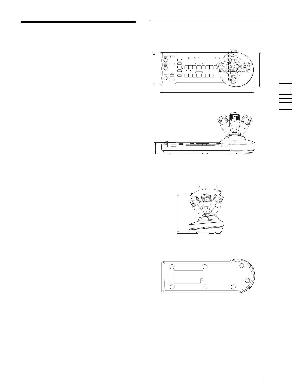
Technische Daten
Ein-/Ausgänge
Steuereingang/-ausgang
VISCA RS-232C OUT: 8-polige
Mini-DIN-Buchse
VISCA RS-422: 9-polige Buchse
TALLY IN/CONTACT OUT: 9-polige
Buchse
Steuersignalformat
9.600/38.400 bps
Daten: 8 Bit
Stoppbit: 1
Stromversorgungseingang
JEITA Typ 4 (DC IN 12V)
Allgemeines
Eingangsspannung
12 V Gleichstrom (10,8 bis 13,2 V
Gleichstrom)
Leistungsaufnahme max.
0,2 A (bei 12 V Gleichstrom), 2,4 W
Betriebstemperatur
0ºC bis +40ºC
Lagertemperatur
–20ºC bis +60ºC
Abmessungen 391,3 × 185 × 145,9 mm (B/H/T)
Gewicht ca. 950 g
Abmessungen
Oberseite
VALUE
LOCK
– +
R
MODE
BRIGHT
– +
B
AUTO
FOCUS
NEAR FAR
MANUAL
ONE PUSH
AUTO
AF
137,2
Vord er se it e
45,9
Seite
RESET
PRESET
SHIFT
DIRECTION
POWER
1
9
STD REV
L/R
1
PANEL
LIGHT
2
10
234567
BLACK
3114
30
LIGHT
POSITION
CAMERA
PAN-TI LT
RESET
12
ONE PUSH
AWB
5136147158
391,3
MENU
16
145,9
Anhang
30
Mitgeliefertes Zubehör
Netzgerät MPA-AC1 (Sony) (1)
Netzkabel (1)
RS-232C-Verbindungskabel (1)
RS-422-Anschlussstecker (2)
Bedienungsanleitung (1)
Änderungen, die dem technischen Fortschritt dienen,
bleiben vorbehalten.
185
Unterseite
Einheit: mm
Technische Daten
17
DE
Page 72
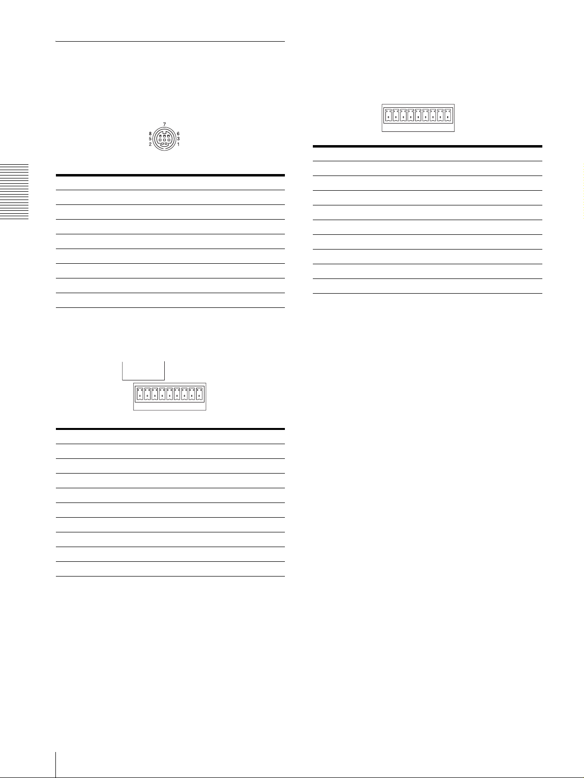
Stiftbelegung
VISCA RS-232C-Ausgangsbuchse (8-polige
Mini-DIN, Buchse)
Buchse TALLY/CONTACT (Anschlussstecker,
9-polig)
TALLY/CONTACT
RS-232C
Stift-Nr. Funktion
1 CAMERA1
Stift-Nr. Funktion
1 Kein Anschluss
2 Kein Anschluss
Anhang
3 TXD IN
4 GND
5 RXD IN
6 GND
7 Kein Anschluss
8 Kein Anschluss
2 CAMERA2
3 CAMERA3
4 CAMERA4
5 CAMERA5
6 CAMERA6
7 CAMERA7
8 GND
9 GND
19
VISCA RS-422-Buchse (Anschlussstecker,
9-polig)
VISCA
RS-422
19
Stift-Nr. Funktion
1 Kein Anschluss
2 Kein Anschluss
3 Kein Anschluss
4 Kein Anschluss
5 GND
6 RXD IN–
7 RXD IN+
8 TXD IN–
9 TXD IN+
DE
18
Technische Daten
Page 73

Verwendung des VISCA RS-422Anschlusssteckers
1
Halten Sie beide Seiten des VISCA RS-422Anschlusssteckers, und ziehen Sie ihn heraus, wie
in der Abbildung gezeigt.
1
9
2
Führen Sie einen Draht (AWG Nr. 28 bis 18) in die
gewünschte Öffnung des Steckers ein, und ziehen
Sie die Schraube für diesen Draht mit einem
Flachschraubenzieher an.
Flachschraubenzieher
Anhang
Draht
3
Führen Sie den VISCA RS-422-Anschlussstecker
in die VISCA RS-422-Buchse ein.
1
9
Hinweise
• Um den Spannungspegel des Signals zu stabilisieren,
sind beide Enden mit Masse (GND) zu verbinden.
• Wenn die Verbindung über die VISCA RS-422Buchsen hergestellt wird, ist die VISCA RS-232CVerbindung nicht verfügbar.
• Die maximale Länge der VISCA RS-422-Verbindung
beträgt ungefähr 1.200 m.
Technische Daten
19
DE
Page 74

Page 75

Page 76

Printed on 100% recycled paper.
Sony Corporation
Printed in Japan
 Loading...