

Page 1
Camera and Electronic Products for Integrators
Installation and User Guide
CEILINGVIEW™ RECESSED CEILING INSTALLATION KIT
For drywall or hard ceiling applications for
the CeilingVIEW 70 PTZ, CeilingVIEW 70
PTZ HideAway and the CeilingVIEW
Document Camera Series
OVERVIEW
The Vaddio Recessed Ceiling Installation Kits were
designed to provide integrators with an easy to install
solution for mounting Vaddio CeilingVIEW cameras and
document cameras into drywall or hard ceiling material
applications. (see Figures 1, 2 & 3). There are two
separate kits available: one kit for the CeilingVIEW 70
PTZ and HideAway camera systems and another kit for
the CeilingVIEW SD and HD Document Cameras.
Both kits allow the integrator to install the document
camera from below the ceiling, and have a trim ring
large enough to cover the entire camera back box.
INTRODUCTION
The Recessed Ceiling Installation Kit comes in two (2) different models for different sized camera module
enclosures.
The 535-2000-210
Kit for the following models:
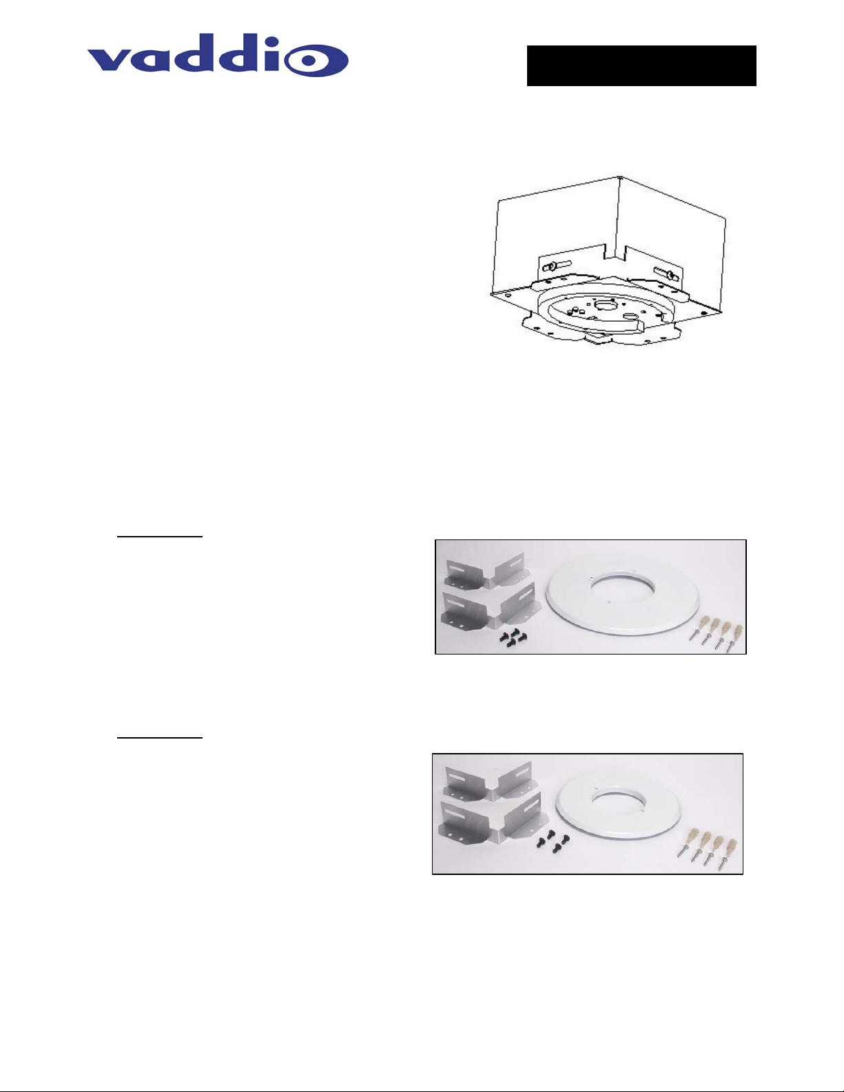
Figure 1:
CeilingVIEW HD with recessed ceiling
installation kit brackets attached
• CeilingVIEW 70 PTZ
o Model 999-2304-000
o Model 999-2304-001(PAL)
• CeilingVIEW 70 PTZ HideAway
o 999-2404-000
o 999-2404-001 (PAL)
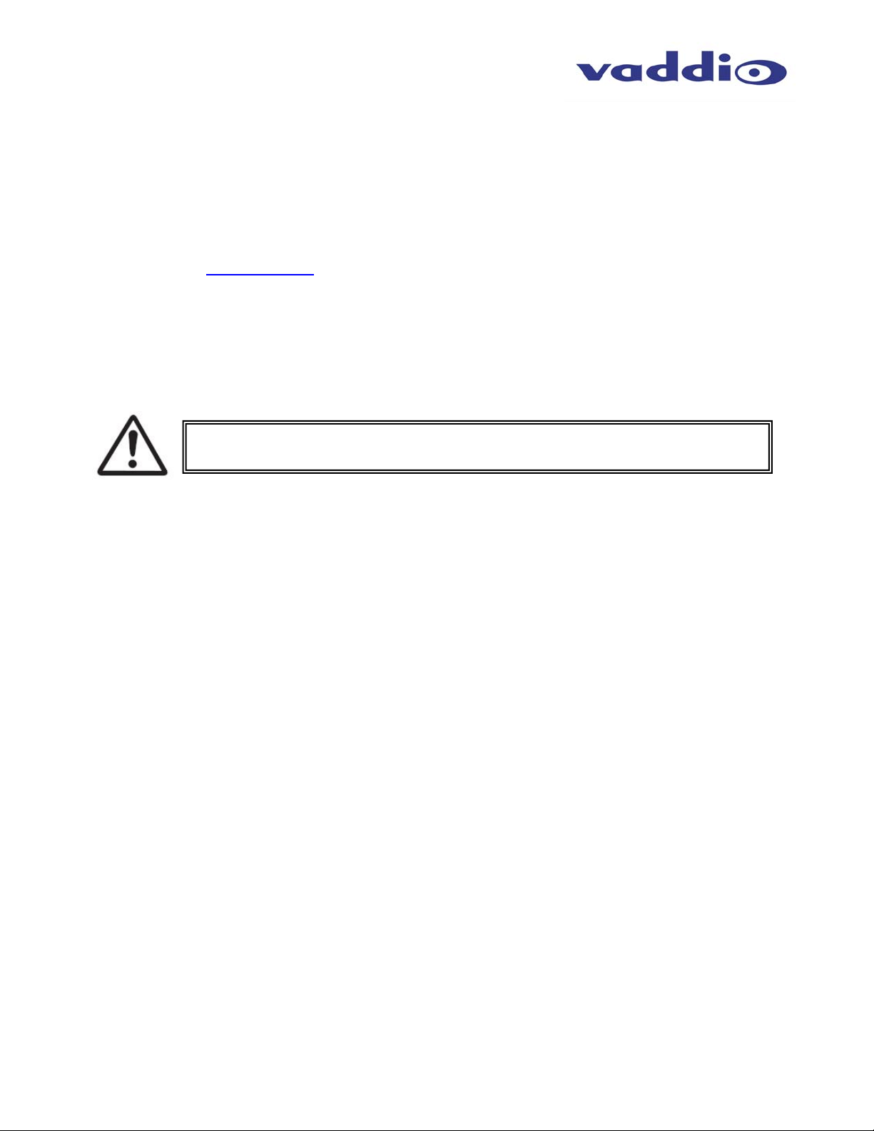
Includes two (2) ceiling mount adapter plates, White
Trim Ring (larger to cover adapter plates) with IR
Figure 2: Recessed Ceiling Kit 535-2000-210
extender board built-in and mounting hardware
The 535-2000-226
Kit is for:
• CeilingVIEW HD
o Model 999-3008-000
o Model 999-3008-001 (PAL)
• CeilingVIEW HD CCU
o Model 999-3009-000
o Model 999-3009-001 (PAL)
• CeilingVIEW SD
o Model 999-2008-000
o Model 999-2008-001 (PAL)
• CeilingVIEW SD CCU
Figure 3: Recessed Ceiling Kit 535-2000-226
o Model 999-2009-000
o Model 999-2009-001 (PAL)
Includes two (2) ceiling mount adapter plates, White Trim Ring (larger to cover adapter plates) and all
mounting hardware
©2008 Vaddio - All Rights Reserved. Reproduction in whole or in part without written permission is prohibited. Specifications and pricing subject to change.
Vaddio, CeilingVIEW, and PowerRite are registered trademarks of Vaddio, Inc. All other trademarks are property of their respective owners. Document
Number 341-264 Rev B.
Page 2
INTENDED USE
Before installing the Vaddio Recessed Ceiling Installation Kit or Vaddio CeilingVIEW Document Cameras,
please read the entire manual thoroughly. All Vaddio camera systems were designed for use indoors.
Outdoor operation is not recommended, hasn’t been tested, and could damage the camera and/or create a
potentially unsafe operating condition. Use only the Vaddio PowerRite power supply provided.
SAVE THESE INSTRUCTIONS
The information contained in this manual will help you install the Vaddio Document Cameras in recessed
ceiling applications. For reference, Vaddio keeps copies of Specifications, Installation and User Guides and
most pertinent product drawings for the Vaddio product line on the website. These documents can be
downloaded from www.vaddio.com
IMPORTANT SAFEGUARDS
Read and understand all instructions before using. Do not operate the any electrical device if it has been
dropped or damaged. In this case, a Vaddio technician must examine the product before operating. To
reduce the risk of electric shock, do not immerse in water or other liquids and avoid extremely humid
conditions.
Use only the power supply provided with the Vaddio CeilingVIEW products. Use
of any unauthorized power supply will void any and all warranties.
INFORMATION
Vaddio has prepared a number of TechNotes, specifications and drawings designed to inform and educate
integrators on the value and the specific uses of Vaddio products.
free of charge.
UNPACKING
Carefully remove all of the parts from the packaging.
Unpack and identify the following parts:
Kit 535-2000-210
• One (1) 14” (35.56) White trim ring with IR sensor board attached
• Two (2) aluminum ceiling mount adapter plates
• Mounting Hardware
o Four (4) - #8 EZ Drywall Anchors with Four (4) - 2” #8 sheet metal screws
o Four (4) – ¼”-20 x ½” Phillips pan head screws and lock washers
o Two (2) – White trim ring screws
• Installation and User Guide
Kit 535-2000-226
• One (1) 10-1/2” (26.67cm) White Trim Ring
• Two (2) aluminum ceiling mount adapter plates
• Mounting Hardware
o Four (4) - #8 EZ Drywall Anchors with Four (4) - 2” #8 sheet metal screws
o Four (4) – ¼”-20 x ½” Phillips pan head screws and lock washers
o Two (2) – White trim ring screws
• Installation and User Guide
CeilingVIEW Recessed Ceiling Installation Kit 341-264 Rev. B Page 2 of 6
Page 3

INSTALLATION
The CeilingVIEW products are integrated document/object cameras specifically designed for installation
above a conference table, lectern or work surface. Recommended ceiling height range is between 8’ and 12’
(2.44m to 3.66m). Make sure the measurements used for rough-openings, image orientation and location
are 100% accurate prior to attempting installation (measure twice, cut once).
Before Installing
• Check above the ceiling tile or drywall where you plan to install the camera to make sure the area is
clear and that there is adequate room for the CeilingVIEW Module and all of its components.
• Pre-wire all cabling as required.
• Please check the individual Vaddio CeilingVIEW Installation and User Guide manuals for special
considerations pertaining to operability specific to the models used (i.e. the CeilingVIEW Document
Cameras, used as part of a multi camera system, are required to be the last camera in the control chain
to support the VISCA daisy chain control standard).
Camera Module Cut-outs
The following table contains the cutout dimensions for the recessed CeilingVIEW back box enclosures.
TABLE 1:
Vaddio Camera & Part Number
CeilingVIEW 70 PTZ 9-1/4” (23.495cm) 535-2000-210
CeilingVIEW 70 PTZ HideAway 9-1/4” (23.495cm) 535-2000-210
CeilingVIEW SD & CCU 6” (15.24cm) 535-2000-226
CeilingVIEW HD & CCU 6” (15.24cm) 535-2000-226
MOUNTING INSTRUCTIONS
The Recessed Ceiling Installation Kits can be installed in finished ceilings, as long as there are no
obstructions above the drywall, or in new ceilings as long as the camera position, orientation and location
over work surfaces is determined prior to installation.
PRE-INSTALLATION INSTRUCTIONS
Pre-wire all cable as required. Cabling after the ceiling is closed up can be challenging and time consuming.
Step 1:
Attach a string or plumb bob to the ceiling where the camera is to be located. Position the string directly over
ample table space or work surface to allow easy document access and object positioning.
Step 2:
Draw the appropriate sized square (from Table 1) onto the drywall centered on the string. Cut out the
marked square or in the case of a new construction have the drywall contractor cut the drywall to the proper
dimension.
Figure 4:
Mark and cut the square in the
drywall for the appropriate camera
Rough-opening
Square Dimension
Recessed
Installation Kit
See Table 1
CeilingVIEW Recessed Ceiling Installation Kit 341-264 Rev. B Page 3 of 6
Page 4

Step 3:
Attach the two (2) aluminum ceiling mount adapter plates with the four (4) – ¼”-20 x ½” Phillips pan head
screws and lock washers.
Figure 5:
Aluminum ceiling mount adapter plate (right)
and shown attached to (below)
Step 4:
Raise the module into the rough opening and mark the four (4) dry wall anchor locations.
Figure 6:
ISO View of CeilingVIEW
module shown marking
locations for drywall anchors
Step 5:
Using the supplied drywall anchors, insert the anchors into the drywall ceiling (Figure 7).
Figure 7:
Drywall anchors attached to
drywall ceiling – pilot holes
maybe required to avoid edge
deterioration on drywall
opening.
Note: Other ceiling types may
need other anchor types (i.e.
toggle bolts) – not supplied.
CeilingVIEW Recessed Ceiling Installation Kit 341-264 Rev. B Page 4 of 6
Page 5

Step 6:
Lift the camera module into place, connect the cables and push the camera firmly into the drywall, fasten the
2” - #8 sheet metal screws through the flange of the ceiling mount adapter plate (Figure 8).
Step 7: For Situations Requiring IR Pass-Thru
For the CeilingVIEW SD and HD Document Cameras, attach the 10-1/2” diameter trim ring to the camera
module with the supplied white screws. This installation should now be complete.
For the CeilingVIEW 70 PTZ and the CeilingVIEW 70 PTZ HideAway, the IR sensor board is included on the
14” diameter white trim ring. As always, take care not to pull any more than about 2 inches of cable out from
the camera enclosure. The connectors will fit together only one way with a positive click. Carefully move trim
ring into position on the bottom of camera while feeding IR cable back into camera enclosure and secure
with the two supplied white screws. Installation for these models should now be complete.
Figure 9:
Left: Small trim ring (10-1/2”)
for CeilingVIEW Visualizer
Right: Larger trim ring (14”)
for CeilingVIEW 70 PTZ and
CeilingVIEW 70 PTZ
HideAway with IR sensor
board mounted to trim ring
Step 8:
See all other individual product installation and user guides for initial power-up and all other functionality and
set-up of the Vaddio CeilingVIEW cameras.
Figure 8:
Cable the camera and attach
camera module to ceiling with the
provided drywall anchor screws.
4-3/4”
10-1/2”
IR Sensor Board
14” Trim Ring Only
5-7/16”
14”
CeilingVIEW Recessed Ceiling Installation Kit 341-264 Rev. B Page 5 of 6
Page 6

CARE AND CLEANING
• Do not attempt to take the products in these systems apart. There are no user-serviceable components.
• Keep these devices away from food and liquid, and do not spill liquids on the products
• For smears or smudges on the lens, wipe with a clean, soft cloth - see Polycom user guide for details.
Do not use any abrasive chemicals on the camera body at any time.
OPERATING AND STORAGE CONDITIONS
Do not store or operate the CeilingVIEW products under the following conditions:
• Temperatures above 40°C (104°F) or below 0°C (32°F), for Indoor Use Only
• High humidity, condensing or wet environments
• Dusty environments
• In inclement weather
• Under severe vibration
WARRANTY INFORMATION
Hardware* Warranty - One year limited warranty on all parts. Vaddio warrants this product against defects in materials and
workmanship for a period of one year from the day of purchase from Vaddio. If Vaddio receives notice of such defects during the
warranty period, they will, at their option, repair or replace products that prove to be defective.
Exclusions - The above warranty shall not apply to defects resulting from: improper or inadequate maintenance by the customer,
customer applied software or interfacing, unauthorized modifications or misuse, operation outside the normal environmental
specifications for the product, use of the incorrect power supply, improper extension of the power supply cable or improper site
operation and maintenance.
Vaddio Customer service – Vaddio will test, repair, or replace the product or products without charge if the unit is under warranty and
is found to be defective. If the product is out of warranty, Vaddio will test then repair the product or products. The cost of parts and labor
charge will be estimated by a technician and confirmed by the customer prior to repair. All components must be returned for testing as a
complete unit. Vaddio will not accept responsibility for shipment after it has left the premises.
Vaddio Technical support - Vaddio technicians will determine and discuss with the customer the criteria for repair costs and/or
replacement. Vaddio Technical Support can be contacted through one of the following resources: e-mail support at
support@vaddio.com or online at www.vaddio.com
Return Material Authorization (RMA) number - Before returning a product for repair or replacement, request an RMA from Vaddio’s
technical support. Provide a technician with a return phone number, e-mail address, shipping address, and product serial numbers and
describe the reason for repairs or returns as well as the date of purchase and proof of purchase. Include your assigned RMA number in
all correspondence with Vaddio. Write your assigned RMA number on the shipping label of the box when returning the product. Please
see Vaddio’s website for current RMA policies and procedures.
Voided warranty – The warranty does not apply if the original serial number has been removed or if the product has been
disassembled or damaged through misuse, accident, modifications, or unauthorized repair. Cutting the power supply cable on the
secondary side (low voltage side) to extend the power to the device (camera or controller) voids the warranty for that device.
Shipping and handling - Vaddio will not pay for inbound shipping transportation or insurance charges or accept any responsibility for
laws and ordinances from inbound transit. Vaddio will pay for outbound shipping, transportation, and insurance charges for all items
under warranty but will not assume responsibility for loss and/or damage by the outbound freight carrier. If the return shipment appears
damaged, retain the original boxes and packing material for inspection by the carrier. Contact your carrier immediately.
Products not under warranty - Payment arrangements are required before outbound shipment for all out of warranty products.
*Vaddio manufactures its hardware products from parts and components that are new or equivalent to new in accordance with industry
standard practices.
Toll Free: 800-572-2011 ▪ Phone: 763-971-4400 ▪ FAX: 763-971-4464
9433 Science Center Drive, Minneapolis, MN 55428
©2008 Vaddio - All Rights Reserved. Reproduction in whole or in part without written permission is prohibited. Specifications and pricing
subject to change. Vaddio, CeilingVIEW, and PowerRite are registered trademarks of Vaddio. All other trademarks are property of their
respective owners. Document Number 341-264 Rev B.
CeilingVIEW Recessed Ceiling Installation Kit 341-264 Rev. B Page 6 of 6
.
www.vaddio.com
 Loading...