

Page 1
Installation and User Guide
Camera and Electronic Products for Integrators
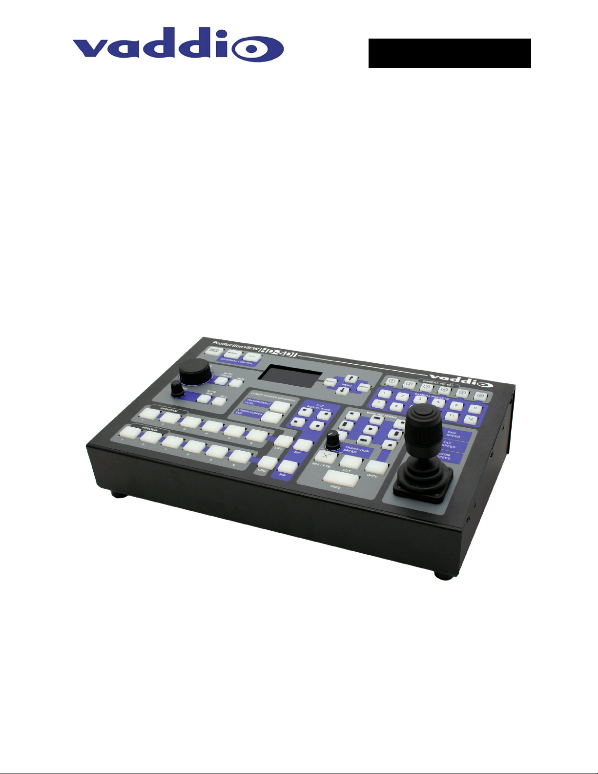
VADDIO™ PRODUCTIONVIEW™ HD-SDI
Camera Control Console with HD/SD-SDI Video Switching, Video
Transitions, Up/Down Converting of Inputs and Outputs, Lower Screen
Graphics and Automated Control Functionality
Model Number 999-5650-000 (NTSC)
Model Number 999-5650-001 (PAL)
©2013 Vaddio - All Rights Reserved. ProductionVIEW HD-SDI - Document Number 341-852 R ev. B
Page 2
ProductionVIEW HD-SDI
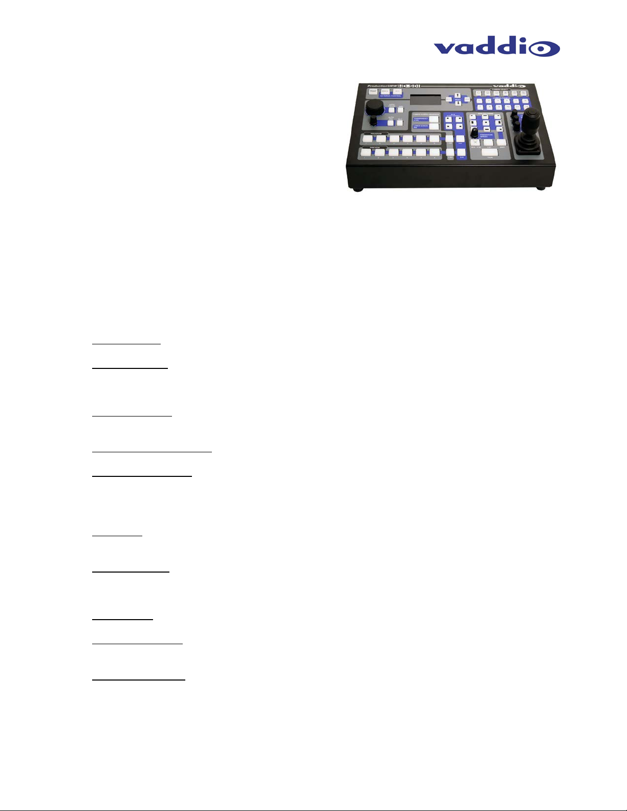
Figure 1: ProductionVIEW HD-SDI Camera Control Console
ProductionVIEW HD-SDI-SDI Overview
The ProductionVIEW HD-SDI-SDI (Figure 1)
incorporates seam less video switching, c amera pres et
control and joystick camera control functionality into
one of the most fully featured video consoles on the
market today. In addition, ProductionVIEW HD-SDI
delivers user selectable H D -SDI or SD-SDI inp uts , and
will up or down scale the outp ut signal to a variety of
resolutions in either HD-SDI o r SD-SDI with o nly one
frame of delay.
Video graphics insertio n (i.e. “lower thir d”) is available through our uniqu e Lower Screen Graph ics (LSG)
feature. LSG allo ws users to insert graphics from a variety of gra phics programs, including Microsoft®
PowerPoint®, Apple® Ke ynote®, MediaShout® or virtually any presentation software application. LSG
provides graphics insertion without the added latency or complexity of luminance or chroma keying.
The ProductionVIEW HD -SDI-SDI c ontrol surf ace is laid out to allow ev en a n ovice t o oper ate t he s ystem
with minimal training.
• Video Switcher -- T he internal video s witcher can be conf igured as a tradit ional video switch er, using
the Take button, or Dual Bus mode.
• Dual Bus Mode – Dual Bus allows users to switch two separate programs (i.e. IMAG for live
presentations on the Progr am output, and a secondary program for a recording of the live event on
the Preview output). The Program output can be a discrete resolution setting from the Preview
outputs. Either set of outputs can be configured for SD-SDI or HD-SDI.
• Graphic Insertion -- Graphics may be inserted as “lower-thirds” using the Lower Screen Graphics
(LSG) feature. LSG can be s et up to c over th e bottom ¼,⅓, ½ or full scr een, with 10 adj us ta ble ste ps
of transparency levels between the graphic and the video image behind it.
• Anything In / Anything Out – The inputs and o utputs have disc rete SDI video res olutio n settin gs. See
the specifications on page 19 for additional information on all of the resolutions supported.
• PTZ Camera Joystick -- T he ProductionVIEW HD -SDI includes a joystick c ontroller to operate up to
six (6) PTZ cameras directly (w ithout daisy chaining) and th e six discrete camera c ontrol ports autosense the PTZ camera attached. Vaddio, Panasonic®, Sony® and Canon® PTZ cameras are
compatible with Pr oductionVIEW HD-SDI (see the list of specific m odels). Each input has a camera
selector to allow 12 preset PTZ positions to be stored.
• Transitions -- On the c ontrol surface, buttons f or the type of effect (dissolve, wip e or cut) as well as
wipe patterns are sel ectable. The transiti on time is adjustable thr ough a knob on the console, from
zero (0) to four (4) seconds.
• Automatic Mode -- The console is equipped with an Automatic Camera Switching Mode (for
compatible PTZ cameras on inputs 1 & 2), and when combined with Vaddio’s StepVIEW Mats,
MicVIEW or other tr igger devices, allows Productio nVIEW HD-SDI to be set up f or use without an
operator present. Preset triggers or Tally Outputs can be used, but not simultaneously.
• Tally Outputs -- The Produc tionVIEW HD-SDI also ha s six Tally outputs for c ontrolling tally lights on
external sources, such as Vaddio’s WallVIEW CCUs and PreVIEW HD monitors.
• Graphic Templates -- A variety of graphic templates are included on a DVD supplied with
ProductionVIEW HD -SDI in both Keynote and Pow erPoint, to help guide us ers to create prof essional
graphics quickly and easily.
• Additional Features – Other features include auto/manual focus, auto/manual iris, backlight
compensation and automatic white balance for compatible PTZ cameras.
ProductionVIEW HD-SDI Manual 341-852 Rev. B Page 2 of 22
Page 3
ProductionVIEW HD-SDI
Use only the power supply provided with the ProductionVIEW HD-SDI
system. Use of any unauthorized power supply will void any and all
Do not use “pass-thru” RJ-45 connectors. Use standard RJ-45
• Camera Auto-Sensing - The ProductionVIEW HD-SDI is capable of auto-sensing each PTZ camera
attached. Control codes for the following cameras are built-in:
• Vaddio WallVIEW CCU and PRO Series Cameras *
• Sony EVI-HD1, & Son y BR C-300, BRC-Z700 & BRC-H700 *
• Panasonic AW-HE100 *
• Canon BU-45H & BU-50H
* Most cameras require an optional SDI card
• Video Transitions
Video transitions are seam less with ex ceptiona l video qualit y. Transition t ime is adjustable fr om zero
(0) to four (4) seconds and include:
• Cross Fades (one image fades into another)
• Wipes (9 different patterns)
• Straight Cuts
• Fade To Black (by pressing, and holding the MIX/FTB button)
Intended Use:
Before operating the Vaddio ProductionVIEW HD-SDI, please read the entire manual thoroughly. The
system was designed, bu ilt and tested for use in doors, and with the prov ided power supply and cab ling.
The use of a power supply other than the one provided or outdoor operation has not be en tested and
could damage the camera and/or create a potentially unsafe operating condition.
Save These Instructions:
The information cont ained in this manual will help you install and operate your Vaddio ProductionVIEW
HD-SDI. If these instruc tio ns are m is placed, Vaddi o k eeps co pies of Sp ecific atio ns, Insta llati on an d User
Guides and most pertine nt product drawings for the Vad dio product line on the Vaddio website. These
documents can be downloaded from
www.vaddio.com free of charge.
Important Safeguards:
Read and understand all i nstructions before usin g. Do not operate an y device if it has been dr opped or
damaged. In this cas e, a Vaddio technic ian must examine the product before operati ng. To reduce the
risk of electric shock, do not immerse in water or other liquids and avoid extremely humid conditions.
connectors for best results.
UNPACKING:
Carefully remove the device and all of the parts from the packaging.
Unpack and identify the following parts:
• One (1) ProductionVIEW HD-SDI Camera Control Console
• One (1) Vaddio PowerRite 18 VDC, 2.78A Power Supply
• One (1) Vaddio AC Cor d S et (US or Euro/UK)
• DVD ROM with templates and sample graphics for Lower Screen Graphics*
• Documentation and Manuals
* User must supply their own compatible version of Keynote or PowerPoint to display and modify templates on the DVD ROM.
ProductionVIEW HD-SDI Manual 341-852 Rev. B Page 3 of 22
Page 4
ProductionVIEW HD-SDI
1234567
1089
ProductionVIEW HD-SDI
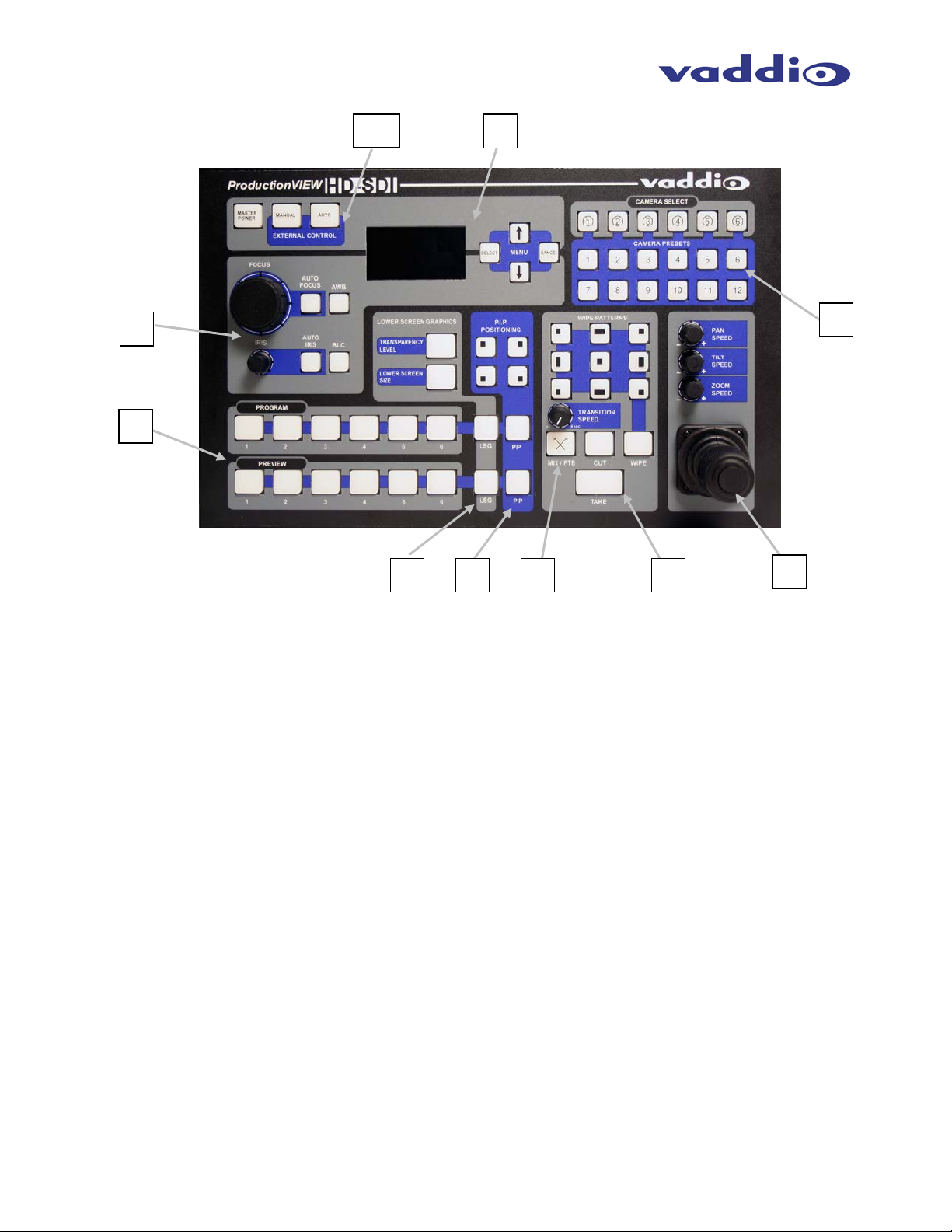
Figure 2):
1. Focus and Iris Controls: Focus and Iris can be adjusted from k nobs on the console for real-time
control of these critical functions, when their respective Auto buttons are turned off. Auto White
Balance (AWB) and Backlight Compensatio n (BLC) func tions are also availab le for compatible PTZ
cameras.
2. Single Bus or Dual Bus Switching: ProductionVIEW H D-SDI can be conf igured as Program and
Preview buses or as discrete video outputs (i.e. one for high resolution IMAG and the other for
delivery to a recording or streaming device).
3. Lower Screen Graph ics: Insert “lower third” and other graphics, t hrough our unique LSG function.
A variety of sizes and transparency levels are available through buttons o n the console. Note: A n
analog RGBHV to SDI converter box is required if using a computer for graphics.
4. Picture-In-Picture: Insert video in any quadrant of the program video output to add impact to your
live production. The PIP can be adjusted to three different sizes.
5. Wipe, Fade, Cut, Transition Speed and Fade to Black: Select a variety of wipe patterns, mix or cut
from buttons on the contr ol console. The Fade t o Black (FTB) f eature allows the Program output to
fade to black. Transition Speed allows a wipe or fade transition to be adjusted up to 4 seconds.
6. Take Button: Pressing the Take button switches the input selected from Preview to Program in
Single Bus mode. In Dual Bus mode, it switches the input to the input that is flashing.
7. Joystick PTZ Camera and Speed Controls: Sony, Canon and Vaddio PTZ cameras can be
controlled via the 3-axis Hall-Effec t joystick built into ProductionVIEW HD-SDI. Adjustable knobs f or
Pan, Tilt and Zoom speeds. When the b utton on top of the jo ystick is pressed, it will reposition the
selected camera to its home position.
8. Camera Selector and Pr e sets: Se lec t a camera from the top row of butt ons , and program ( or r ecall)
up to 12 preset shots per camera, using the camera preset control buttons.
9. Menu and LCD Screen: The internal menu allows the user to configure the resolution on the
outputs, as well as other parameters built into the console. See pages 13 to 16 for the menu
structures and programmable functions.
10. Manual and Automatic Modes: In addition to a manua l or “operator” mode th ere is an Automatic
Camera Switching mode for PTZ camera presets assigned to Vaddio input triggers like the
StepVIEW™ mats, AutoVIEW™ IR or TouchVIEW™ buttons.
ProductionVIEW HD-SDI Manual 341-852 Rev. B Page 4 of 22
Page 5
ProductionVIEW HD-SDI
111213
1415161718
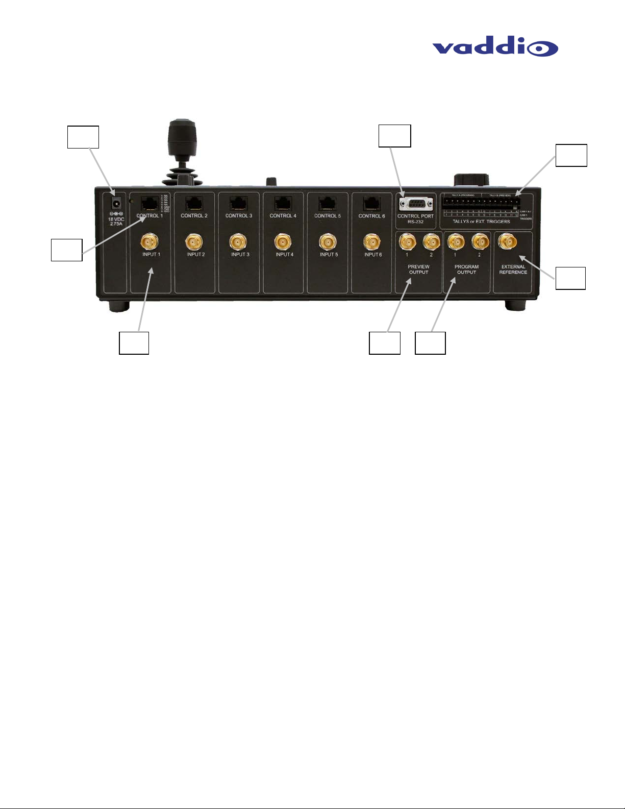
ProductionVIEW HD-SDI Back Panel I/O and Controls (Figure 3):
11. Power Input - Note: Use only the 18 VDC, 2.7 5A power supply provid ed with the ProductionVIEW
HD-SDI.
12. Camera Control Ports on RJ-45 connectors: One camera control port per camera (no daisychaining required) . Compatib le with Son y, Canon and Va ddio PTZ c ameras. See pa ge 3 for deta ils
on cameras and camera systems compatible with ProductionVIEW HD-SDI.
13. HD/SD-SDI Inputs: Each input will accept either an SD -SDI or HD-SDI video sig nals (selectable v ia
internal menu) on the BNC connectors. See the Video Resolutions table on page 20 for all signals
and resolutions supported.
14. Preview HD/SD-SDI Outputs – Delivers the sam e SD-SDI or HD-SDI sig nals (s electable v ia internal
menu) on both BNC connectors. See the Video Resolutions table on page 20 for all signals and
resolutions supported.
15. Program HD/SD-SDI Outputs – D eliv er s the s ame SD-SDI or HD-SDI sign als (selectable via intern al
menu) on both VGA connectors. See the Video Resolutions table on page 20 for all signals and
resolutions supported.
16. External Reference – For connecting “house sync” to Preview and Program outputs when
connecting Production VIEW HD-SDI to another s witcher/m ixer. Bec ause Produ ctionVIEW HD-SD I is
a seamless switcher , none of the inputs hav e to be sync’d, only the outputs. Note: If the External
Sync option is used, the Pr eview and Program outputs must be configured f or the same resolution
(i.e. 1080i/59.94, 720p/59.94, etc.).
17. Tally Outputs/Trigger Inputs – Select either to use the connect ors as Tally Out puts to exter nal tall yenabled products, such as Vaddio’s Quick-Connect CCUs. Input Triggers allow Vaddio’s trigger
devices to be used in automating c amera presets for inputs 1 and 2. Conf igurable in two m odes (6
triggers for Input 1 and 6 triggers for Input 2, or 12 triggers for input 1 only). Supports Vaddio
AutoVIEW IR, StepVIEW, TouchVIEW and MicVIEW trigger devices, which are sold separately.
18. Control Port Input - DB-9 for RS-23 2 control of inter nal functions (Pi n 2 = TX, Pin 3 = RX, Pin 5 =
GND).
ProductionVIEW HD-SDI Manual 341-852 Rev. B Page 5 of 22
Page 6
ProductionVIEW HD-SDI
First Time Set-up with the ProductionVIEW HD-SDI:
ProductionVIEW HD -SDI was designed t o be exceptionall y easy to use and operate r ight out of the box .
All of the Vaddio standards for using video (analog), power and control over Cat. 5 cabling are well
documented and are in the manual and available free of c harge from the Vaddi o website. HD-SDI and
SD-SDI video signals need to be transmitted over coax cabling that is capable of handling SDI signals.
Getting Started:
Connect all of the cameras, monitors and peripheral devices to ProductionVIEW HD-SDI. The back panel
has BNC connectors. On the nex t page is a diagram showing how to connect a Vaddio WallVIEW H700
CCU to ProductionVIEW HD-SDI. See Figures 4 & 5 for additional information.
NOTE: When connecting Pan asonic HE100 PTZ camer as to the system, you must select Panaso nic in
the Cam Search Menu (see page 15 for additional detail on this menu).
Once you have connected all of your inputs, outputs and the Po werRite power supply, plug the AC c ord
into an outlet. ProductionV IEW HD-SDI will boot up and scan f or cameras. As ProductionV IEW HD -SDI
boots up, it will automatically scan eac h input to confirm which ports have compati ble PTZ cameras or
Add-A-Cam systems connec ted. Af ter boot up, a menu will appear on the blue L CD sc r een. At this poi nt,
some cameras may not be detected by Produc tionVIEW HD. This s ituation will be resolved b y following
the instructions below for configuring the system for the appropriate input/output resolutions, cameras that
are connected to the system, etc.
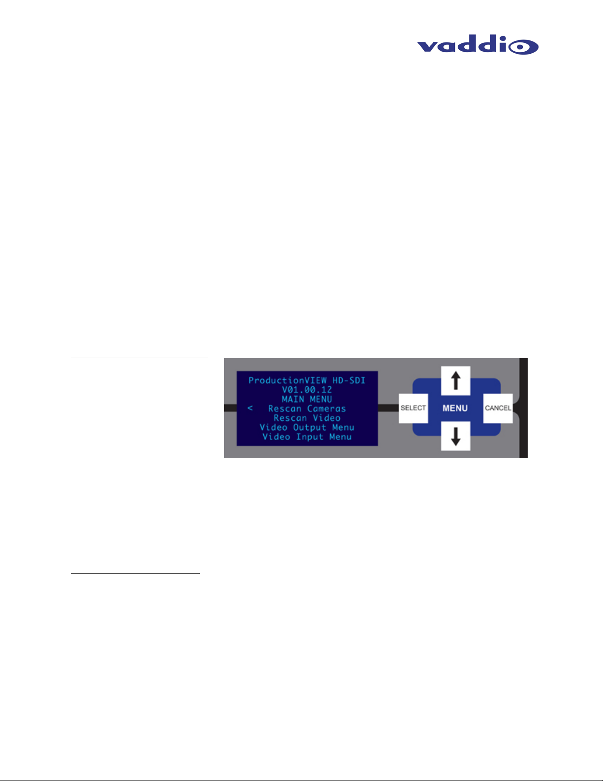
Configuring Output Resolutions
On the LCD screen, a chevron
(>) will be displayed next to the
menu item that is currently
selected. Press the Arr ow Do wn
Button (↓) adjacent to the LCD
screen, until the che vron is next
to “VIDEO OUTPUT MENU” and
then press the SELECT button.
Select PROGRAM OUTPUT,
which will d isplay your opti ons for video output resolu tion for the PROGRAM OUT PUT. Arrow down to
the appropriate resolution that is compatible with your video monitor, then press the SELECT button.
Then, press the CANCEL button to exit out to the previous menu.
Repeat the process f or your Preview Output. O nce you have selected th e Program and Previe w output
resolutions, press the C ANCEL button to get back to the Main Menu. For add itional information on the
menu tree structure, see pages 13 to 16 for additional information.
Configuring Input Resolutions
From the Main Menu, pres s the down arrow button, to move the c hevron to VIDEO INPUT MENU, an d
then press the SELEC T button. If all input devices have the same resolution (i.e. 1080i / 59.94), then
select ALL PORTS. If not all inp uts have the same resolution, the n press the down arrow button t o the
first input with a vide o device attac hed, and pr ess SELECT . Choose the a ppropriate video resoluti on for
the video device connec ted to the input, an d then press SELECT . Press the CANC EL button to exit th e
resolution setting for the input. Repeat the process for all video inputs.
NOTE: Whether an input is a PTZ camera, or another video source, the input signal will need to be configured to the
proper video resolution of the device connected.
ProductionVIEW HD-SDI Manual 341-852 Rev. B Page 6 of 22
Page 7
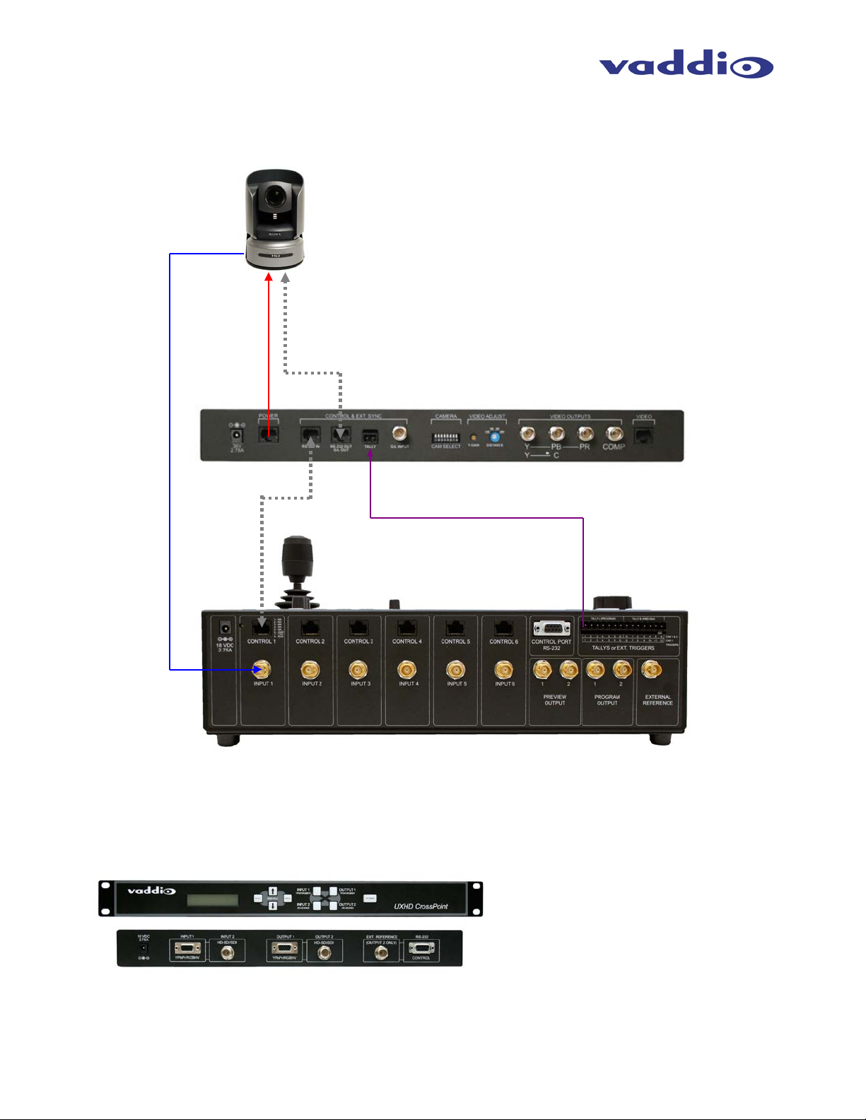
ProductionVIEW HD-SDI
WallVIEW CCU H700 with
Figure 4:
RS-232
TALLY IN
HD-SDI
Power
UXHD CrossPoint is a dual input (SD/HD-SDI & analog
CrossPoint.
RS-232
TALLY OUT
ProductionVIEW HD-SDI
Quick-Connect CCU
HD-SDI
Sample configuration of a WallVIEW CCU connected to ProductionVIEW HD-SDI, with video, control and tally cabling.
Coax Cable
CAT 5
Control
Optional Accessory – UXHD CrossPoint (999-5690-000)
ProductionVIEW HD-SDI Manual 341-852 Rev. B Page 7 of 22
optional HD-SDI Card in camera
CAT 5
video), dual output (analog video & SD/HD-SDI)
converter. The CrossPoint allows si gnal conversion for
delivering video into and out of ProductionVIEW HD-SDI.
See the next page for a line drawing with UXHD
Page 8

ProductionVIEW HD-SDI
Figure 5:
UXHD CrossPoint
(Sold separately)
HD-SDI Monitors
RGBHV
HD-SDI
HD-SDI
RGBHV
PC
RGBHV
IN
IN
OUT
OUT
WallVIEW
WallVIEW
WallVIEW
HD-SDI
HD-SDI
HD-SDI
Preview HD-SDI
Program HD-SDI
HD-SDI
Multiple WallVIEW CCU camera systems and laptop connected to ProductionVIEW HD-SDI, with SDI monitors. A
laptop and the program output of ProductionVIEW HD-SDI are connected to the optional UXHD CrossPoint converter
for conversion to and from SDI. NOTE: PTZ Cameras below either have SDI accessory cards, or native SDI outputs.
CCU
HD1
CCU
Z700
CCU
H700
COAX
COAX
COAX
(PROG
OUT)
(PC Signal)
(HD-SDI
PROG)
COAX
Projector
ProductionVIEW HD-SDI Manual 341-852 Rev. B Page 8 of 22
Page 9

ProductionVIEW HD-SDI
Operating the ProductionVIEW HD-SDI:
Most of the consol e functions and controls are eas y and intuitive. Over the nex t few pages there are
details on how the different functions operate.
Camera Controls
The controls that can be used to adjust a PTZ
camera are highlig hted in the diagram to th e right
(mechanical functions are i n gr ay, and electronic in
blue).
ProductionVIEW HD-SDI is shipped with “Select
Follow Preview” as the default setting. In this
configuration, the camera that is selected on the
Preview bus will automatically choose the
appropriate Camera Select button in the upper
right corner. In this example, Input 1 is a PTZ
camera on the Preview bus and the Camera
Select is illuminated on Input 1 (“1” with a circle
around the number) . The Camera Presets belo w,
are available for storing camera preset positions
and recalling the stored presets.
3-Axis Joystick: Within the menus, the 3-axis joystick is programm able for pan, tilt and zoom direc tion
control. The zoom-in/zoom-out, tilt-up/tilt-down and pan-left/pan-right commands can be inverted on all 3axis to customize cont rol of the PTZ cameras attached to ProductionVIEW HD-SDI. Pan, Tilt and Zoom
speed can be adjusted on controls above t he joystick . NOT E: The speed s ettings ar e discrete on a percamera basis.
Preset Location Storage Options: This feature allows the user to store 12 camera presets in the
ProductionVIEW HD -SDI or have the opt ion of storing 6 camera pr esets (1 through 6) in t he camera and
6 presets (7 through 1 2) in the ProductionVIEW HD-SDI. When storing the presets in the camera, the
user is allowed to speed switch camera presets. Please see the ProductionVIEW HD-SDI Menu
Structure, System Menu for access to the Preset location parameter.
Setting Camera Presets : To program PTZ camera pres ets, press and hold th e Camer a Select button for
five seconds. The Camera Presets buttons (1 thru 12) will begin to flash. Move the camera to the
desired PTZ position, and select one of the Camera Pres ets buttons to store the position. Repeat the
process for each pres et position that is required to be stored, up to 12 tota l positions per PTZ c amera. A
non-flashing preset button has a location stored, but can be overwritten.
Select Follows Preview: When “Select Follows Pre view” is activated, the camera selected for control is
the camera selected by the Preview bus selection. The operator selects the camera to be previewed, and
control (joystick and cam era control) is transferred to that cam era. NOTE: The default position for this
feature from the factory is ‘on’.
Focus, Iris, Auto W hite Balance and Bac klight Compens ation: W hen the Auto Focus or Auto Ir is buttons
are turned off, the manual f ocus and iris k nobs can be used to adjus t these functions on compatible PT Z
cameras that are connected to the system. Auto White Balance (AWB) automatically adjusts the
camera’s color setti ngs b as ed o n lighting and other factors. Backlight Compensation (BLC) opens the ir is
to allow objects in front of windows and other bright backgrounds to be more visible.
NOTE: Backlight Compensation can only be used when the Auto White Balance is turned on.
Dual Bus Mode: Select Follow Preview is disabled when the system is set for Dual Bus mode.
Note: Camera presets contain all the camera information besides the Pan/Tilt/Zoom position including brightness,
focus, backlight, zoom-speed and others as well. The particular control saved under each camera preset is a
function of the parameters available on a per camera basis. Note: camera presets will not sa ve s peci f ic s et ti ng s of a
Quick-Connect CCU, if it is connected to ProductionVIEW HD-SDI.
ProductionVIEW HD-SDI Manual 341-852 Rev. B Page 9 of 22
Page 10

ProductionVIEW HD-SDI
Wipe, Dissolve or Cut
To set up the switcher to transition from the current
input selected as the Program output to another
input, select a diff er ent vide o s ign al o n th e Pre vi e w
bus. In the example to the right, Program is on
Input 1 and Preview is on Input 3.
Select the type of effect (wipe, c ut or mix) that the
switcher will use t o transiti on from one i nput to the
other. Pressing the Take button will execute the
transition from one input to the other, using the
selected transition (mix, cut or wipe).
Changing Effect: T o chang e the type of transition -- W ipe, Cut or M ix -- select that ef fec t above the T ak e
button.
Changing Transition Speed: Both the Mix and Wipe effec ts can be adjusted from .01 to 4 sec onds, by
adjusting the Transition Speed knob, which is located above the Mix button.
Transitions in Dual Bus Mode: Both Program and Preview will allow for transitions (the sam e type of
transition will occur on both outputs). T o select the input that will replace th e current out put on each bus ,
press the input th at will becom e the next s ignal sen t to the output f or either both bus es, or one bus. T he
input signal that each bus will switch to will flash. Press the Take button, and the transition will occur from
the current output to the next one on each bus, one after the other. The other option for making a
transition is to press the flashing button a second time, which will execute the switch from the current
(solid lit button) video signal, to the next video signal (flashing button).
Fade To Black
The Fade To Black feature allows a user to fade
the Program outputs to black, and then fade the
outputs up from black . To have the outputs fade
to black, press and ho ld the MIX/FTB button for
more than one second. The outputs will start
fading to black.
At the point where it is appropriate to fade up
from black, press and hold the MIX/FTB button
again, and the Prev iew and Program outputs will
return to their selected video inputs that were
selected prior to pressing FTB.
FTB Speed: The speed at whic h th e s ignal f ades i n a nd out c a n be a dj us ted thro ugh t h e in terna l menu of
ProductionVIEW H D-SDI. Speed ranges from 01 to 40 (.01 to 4.0 seconds). See the ProductionVIEW
HD-SDI Menu Structure section of this manual for the location of the internal menu that adjusts FTB
timing.
Dual Mode FTB: Pressing and hold ing FTB in Dual Mode allows both the Pre view and Program outputs
to fade to black.
Note: FTB transition time is adjusted via the internal menu of ProductionVIEW HD-SDI, not from the Transition Speed knob.
ProductionVIEW HD-SDI Manual 341-852 Rev. B Page 10 of 22
Page 11

ProductionVIEW HD-SDI
Lower Screen Graphics
Preparing to display Lower Screen Graphics on
ProductionVIEW HD-SDI, first select your
“background” video i nput (typicall y a live camer a) on
the Program bus, a nd then select the i nput that has
the computer graphics that are to be displayed, on
the Preview bus. In the example to the right, the
background is Input 1 on Pr ogram, and the computer
is on Input 6. To initiate the Lo wer Screen Graphic,
press one of the LSG buttons on either bus, a nd the
graphic will appear.
Transparency Level: To increase or decrease the transparency of the graphic overlay, press and hold the
Transparency Level b utto n down. The system will tog gle thr ou gh t he le vels to a l l o w the us er t o s elec t the
level that is appropriate for the graphics.
Lower Screen Size: To in crease or decrease the size of the graphic overlay, press and hold the Lower
Screen Size butto n. T he system will toggl e t hroug h t h e si zes ( bot tom ¼, ⅓, ½ or full sc r een), to allow the
user to select the level that is appropriate for the graphics that have been created.
Increasing/Decreas ing T r ans parency Level and Lower Scr een S ize: When LSG is activ ated , pres s in g t he
PIP Upper Left Button will allo w both T ransparenc y L evel and Lo wer Sc reen S ize to incr ease when ei ther
button is pressed. Pressing the Lower Left PIP button will allow the LSG controls to decrease to
decrease when either button is pressed. Note: This feature does not work in Dual Bus mode.
LSG In Dual Bus Mod e: I n Dual Bus Mode, wher e s ea mless switched outputs wit h ef fects and transitions
can be delivered out of both the Pr eview and Program outputs, select the Input on eac h bus that will be
the “background” im age. Next, s elect the input t hat ha s the com puter graphics th at will be dis played ( the
second button that is pressed on each bus will flash). Press the LSG buttons on the Program and
Preview buses. The graphics will placed on each output seamlessly.
LSG Presets: Preset configurat ions for LSG can be set up utilizing the Camera Preset buttons in the
upper right of the c onsole. Up to 12 preset configurations of lower scr een size and transparenc y level
can be programmed. To do this, with LSG mode turned on, simply set a Lower Screen Size and
Transparency Level. Next, press and hold one of the 12 Camera Preset buttons for approximately 4
seconds. The Lower Sc ree n Si ze and T r ans pare ncy Level will be stored i n tha t preset position, muc h lik e
a camera preset can be s tored in the s ystem. Change the Trans parency Level an d/or Size and s tore the
new preset in one of the ot her 12 Camera Preset selector buttons. A total of 1 2 LSG presets can be
stored in the system. The last LSG pres et p os iti on d isplayed will be the one recalled when L SG is tur ned
back on. Currently, the preset positions for the LSG can only be changed when LSG is turned on.
Note: A DVD containing sample graphics in both Keynote and PowerPoint is supplied with ProductionVIEW HD. The
sample graphics provide users with an easy way of getting started creating graphics for their own live productions.
PIP Display
To set up and display a Picture-In-Picture on the Program output, select the input that will be the
“background” on the Program bus. Select the video input that will be the picture-in-picture, or in the
“window” on the sc reen. In the example to the right, the back ground is Input 1 on th e Program bus and
Input 3 is the window on the Preview bus.
Next, select the corner that the PIP window will show up in, using the P.I.P. Positioning buttons (upper left,
upper right, lower left and lower right). In the illustration to the right, the lower left is selected.
ProductionVIEW HD-SDI Manual 341-852 Rev. B Page 11 of 22
Page 12

ProductionVIEW HD-SDI
PIP Display (continued)
To display the PIP, press either of the PIP
buttons, and the PI P will appear on the sc reen.
Input 3 will now be displa yed in a windo w in the
lower left corner of the screen.
Changing PIP Size: To c hange the size of the
PIP (small, medium or large), press and hold
the PIP Positionin g b utto n and ProductionVIEW
HD-SDI will toggle through the sizes.
PIP In Dual Mode: If ProductionVIEW HD -SDI is set up for Dual Mode (independently s witc hed live f eeds
on Preview and Program buses), select the background sour ce. Next, select the PIP source, which wil l
flash. Press the PIP button f or that spec ific bus , and the window will be dis played. Pr ess the PIP button
to remove the window from the screen. PIP is discrete for the Program and Preview buses when the
system is in Dual Mode.
Master Power, Manual and Auto Modes
If ProductionVIEW HD-SDI is to be used with
an operator at the console, the Manual mode
button will need to be illuminated.
Pressing the Auto button will activate the Auto
mode, which is a configuration when
ProductionVIEW HD-SDI is used in c onjunction
with Vaddio’s StepVIEW mats, MicVIEW
system and AutoVIEW IR sensors or other
trigger devices. These triggers allow
ProductionVIEW HD-SDI to automatically
switch between camera inputs and preset
camera positions. In this mode, no operator is
required.
The mats and sensors can be placed in locations, such as podiums, white boards, etc. to allow the
system to be run in “ Presenter” or Auto m ode. No oper ator needs to be pr esent when the system is set
up in Auto mode. Camera switching and PTZ movements are handled by ProductionVIEW automatically.
Master Power Switch
• When the Master Po wer Switch is powered dow n, all of the attached cam eras will be placed in
standby. Press and hol d th e po w er s witc h f or 3 s ec on ds to in it iate po wer down sequence. This is
a safeguard to prevent accidental shutdown.
• When the Master Power Switch is powered up, all attached cameras will activate and select
default camera and preset inf ormation as def ined in the m enu. The Produc tionVIEW HD-SDI will
scan the inputs for cam era type and video signal type and aut o-configure accord ingly. This can
take up to one minute and is normal operation.
• Note: When the camera co ntr ol p orts ar e changed or reconfigured, the “Rescan Cameras ” opt io n
in the menu must be s elected and started to r escan the cameras and re load the proper control
codes. If only the video in puts are cha nged, the n activate the R escan V ideo fun ction in the Main
Menu to reset the video input priorities.
ProductionVIEW HD-SDI Manual 341-852 Rev. B Page 12 of 22
Page 13

ProductionVIEW HD-SDI
Menu Section
ProductionVIEW HD-SDI Menu Structure
The ProductionVIEW HD-SDI has an 8-line LCD that displays the system menus. The menus are traversed with the
up/down arrows, select and cancel buttons. The menu structure is as follows:
st
1
Screen ProductionVIEW HD-SDI
V01.00.00 (software version)
Rescan Cameras
Video Output
Video Input
Rescan Cameras
>Select (Note: Rescans all RS-232 ports for camera inputs)
>Start
Rescan Video
>Select (Note: Resets all inputs, outputs and video processor)
>Start
Video Output Menu
>Select
>Video Output
>Program Output
HD 1080p 30 Hz
HD 1080p 25 Hz
HD 1080i 59.94 Hz
HD 1080i 50 Hz
HD 720p 60 Hz
HD 720p 50 Hz
SD 480i 29.97 Hz
SD 576i 25 Hz
>Preview Output (NOTE: Same resolution options as Program Output menu)
Video Input Menu
>Select
Default Camera (Automatic and Start-up Modes – the default input selected on the Program bus when the system is turned on)
>Select
> 01 – 06
Default Preset (Automatic Mode – the default preset that the camera is sent to when the system is in Auto Mode. Only reverts to
the configured default position after a trigger has been activated in Auto Mode)
>Select
> 01 – 12
Assigns camera preset 1 through 12 as Default Preset on the default camera (default is 01)
Default Idle Rtn (Automatic Mode only using an external trigger such as a StepVIEW Mat)
>Select
>00 – 60
HD 720p 59.94 Hz
>All Ports (NOTE: Selecting ALL PORTS will configure all inputs to the same resolution)
Port 1 (NOTE: Same resolution options as Program Output menu)
Port 2
Port 3
Port 4
Port 5
Port 6
Selects inputs 1 through 6 as the default camera (default is 01)
Default Camera Idle Return Timer - with no other trigger input, the system returns to the Default Camera and
Default Preset after this time elapses (default is 10, 00 disables function)
ProductionVIEW HD-SDI Manual 341-852 Rev. B Page 13 of 22
Page 14

ProductionVIEW HD-SDI
Pan Dir Menu (Pan Direction Menu)
>Select
>All Ports: Normal or Invert (default is Normal) Inverts the Joystick Pan Direction (Inverted - left = right)
>Port 01: Normal or Invert
>Port 02: Normal or Invert
>Port 03: Normal or Invert
>Port 04: Normal or Invert
>Port 05: Normal or Invert
>Port 06: Normal or Invert
>Return to Main
>Select Returns to Main Menu
Tilt Dir Menu (Tilt Direction Menu)
>Select
>All Ports: Normal or Invert (default is Normal) Inverts the Joystick Tilt Direction (Inverted - up = down)
>Port 01: Normal or Invert
>Port 02: Normal or Invert
>Port 03: Normal or Invert
>Port 04: Normal or Invert
>Port 05: Normal or Invert
>Port 06: Normal or Invert
>Return to Main
>Select Returns to Main Menu
Zoom Direction
>Select
>Normal or Invert (default is Normal)
Inverts the Joystick Zoom Direction (Inverted - Clockwise tw i st = zoom out)
Preset Pan Speed
>Select
>01 – 24 (default is 18)
Sets the Pan Speed on all cameras between camera presets (24 is fastest)
(This parameter does not affect the Pan Speed or sensitivity of the Joystick)
Preset Tilt Speed
>Select
>01 – 20 (default is 15)
Sets Tilt Speed on all cameras between camera presets (20 is fastest)
(This parameter does not affect the Tilt Speed on the Joystick)
Preset Zoom Speed
>Select
>00 – 07 (default is 04)
Sets Zoom Speed on all cameras between camera presets (06 is fastest
Triggers/Tally
>Select
>Trigs 6 Cam/Cam 2
>Trigs All 12 Cam 1
(External Trigger Assignment - 6 triggers each for cameras 1 and 2, or all 12 triggers for camera 1 presets
Triggers work in Automatic Mode Only)
>Tally A=PGM B=PRE
>Tally A+B=PGM
Select Follow Preview
>Select
>On or Off
When activated, camera selection switching follows the Preview bus selection, immediately transferring j oys tick
and camera control directly to the camera selected on the Preview bus (On is default). NOTE: This function
only works in Single Bus Mode – and not in Dual Bus Mode.
ProductionVIEW HD-SDI Manual 341-852 Rev. B Page 14 of 22
Page 15

ProductionVIEW HD-SDI
Cam Search Menu
>Select
>All Ports: (select search method – Auto, Sony, Canon, Panasonic*, No Camera**)
>Port 01: (select search method – Auto, Sony, Canon, Panasonic, No Camera)
>Port 02: (select search method – Auto, Sony, Canon, Panasonic, No Camera)
>Port 03: (select search method – Auto, Sony, Canon, Panasonic, No Camera)
>Port 04: (select search method – Auto, Sony, Canon, Panasonic, No Camera)
>Port 05: (select search method – Auto, Sony, Canon, Panasonic, No Camera)
>Port 06: (select search method – Auto, Sony, Canon, Panasonic, No Camera)
*NOTE 1: It is highly recommended that when using Panasonic cameras, to select Panasonic to speed up the
recognition of the cameras when ProductionVIEW HD-SDI is turned on.
**NOTE 2: By setting a port to “No Camera”, the ProductionVIEW will not scan that port for a camera type.
This allows for a faster boot up when a 3 or 4 camera system is used.
CCU Mode
>Select
>All Ports: (Select method – Direct Cam Ctrl or CCU)
>Port 01: (Select method – Direct Cam Ctrl or CCU)
>Port 02: (Select method – Direct Cam Ctrl or CCU)
>Port 03: (Select method – Direct Cam Ctrl or CCU)
>Port 04: (Select method – Direct Cam Ctrl or CCU)
>Port 05: (Select method – Direct Cam Ctrl or CCU)
>Port 06: (Select method – Direct Cam Ctrl or CCU)
NOTE: When Vaddio Quick-Connect CCUs are used with ProductionVIEW HD-SDI, CCU mode disables Iris
functions, AWB and BLC on the ProductionVIEW HD-SDI console, allowing the user to control these functions
from the Quick-Connect CCU)
System Menu
>Select
>Serial Input
>Select
>Yes or No
Turns on or off serial input (default is Yes)
>Serial Echo
>Select
>Yes or No
Turns Serial Echo on or off (default is Yes)
>Serial Info
>Select
>On or Off
Reports button pushes on front panel out the serial port (default is Off)
(Does not report joy stick position)
>Panel Lights
>Select
>00 through 50
Panel Light Brightness (all lights - 50 is the brightest) (default is 25, off is 00)
>Clear Memory
>Select
>Start
Clears the camera preset memories and sets all parameters to default settings
>Clear Presets
>Select
>Start
Clears the camera preset memory only
>Power Up Preset
>Select
>Home Camera
>Select - Upon power up, all cameras will go to their home position
>Preset 12
> Select - Upon power up, all cameras will go to Preset 12
ProductionVIEW HD-SDI Manual 341-852 Rev. B Page 15 of 22
Page 16

ProductionVIEW HD-SDI
Note: Gen Lock allows the user to send the preview and program outputs
Note: Program Lockout prevents a user from selecting a different source on the
selecting an input on the Preview bus, and then pressing the Take button.
NOTE: See page 2 for additional information on Dual Bus mode,
Note: Turning off the Home feature prevents the camera from going to
Note: When any trigger devices (i.e. StepVIEW Mats, etc.) are added or removed,
currently connected to the system.
>Local
>6 InCam 6 Local
>Single Mode (Default)
>Dual Mode
>Preset Location
In “Local” mode, the ProductionVIEW stores all 12 presets internally
In “6 InCam 6 Local” mode, the presets 1 through 6 will be stored in the cameras.
Presets 7 through 12 will be stored in the ProductionVIEW.
Note: The “6 InCam 6 Local” mode allows for switching video sources when cameras are moving
to preset locations. Since Presets are stored in Camera, the system does not have
to wait for position feedback before allowing another command to be entered.
>Switching Mode
>Transition Swap (Default is On)
>On
>Off
>Settle Time (Default is 20)
>Select
>01 to 90
>FTB Time (Default is 10)
>Select
>10 to 40
>Program Lockout (Default is On)
>Select
>On
>Off
>Gen Lock (Default is Off)
>Off
>HD 1080i 59.94 Hz
>HD 1080i 50 Hz
>SD 480i NTSC
>SD 576i PAL
>Home (Default is On)
>Off
>On
>Init Triggers
>Start
>Select
Note: Settle time allows the user to s et up the time delay between press ing the Take but ton and
when the next button can be selec ted on the console. With a l ower settle time, t here is a
greater chance that a blue screen will appear on the Program output, when the video is
switched quickly, and repeatedly. In m ost applications this will not be an issue. In Singl e
Bus Mode, a faster Settle Time will also create a video roll on the Preview output, which
again in most situations will not be an issue.
Note: FTB Time allows the user to set up a length of time that a fade to black on the Program
Output will occur. 10 is equal to 1.0 seconds, 11 is equal to 1.1 seconds, etc. FTB is
executed on ProductionVIEW HD by pressing and holding the Mix/FTB button for more
than 2 seconds.
>HD 720p 59.94 Hz
>HD 720p 50 Hz
the home position when the button on top of the joystick is pressed.
the user must initiate the Start command to recognize what input triggers are
Program bus of the switcher. All switching of inputs must be accomplished by
to a master control switcher or routing matrix that requires a synchronized
signal. NOTE: The Gen Lock input, preview and program outputs must
all be at the same resolutions.
as well as descriptions on pages 9 – 12.
ProductionVIEW HD-SDI Manual 341-852 Rev. B Page 16 of 22
Page 17

ProductionVIEW HD-SDI
Compliance and CE Declaration of Conformity
FCC Part 15 Compliance
This equipment has been t ested and found to c om ply with th e lim its for a C lass B digit al de vice, purs uant
to Part 15 of the FCC Rules. T hese lim its are desi gned to pro vide reaso nable p rotection ag ainst harm f ul
interference when the e quipment is operated in a commer cial environment. This equipment generates,
uses, and can radiate radio frequency energy and, if not installed and used in accordance with the
instruction manual, may cause harm f ul inter f erenc e t o r adio communications. Ope r ation of th is equipment
in a residential area is likely to cause harmful interference in which case the user will be required to
correct the interference at his/her own expense.
Operation is subject to the f ollowing two conditions: (1) This device m ay not cause interference, and ( 2)
This device mus t accept any interference including inter ference that may cause undesired oper ation of
the device.
Changes or modific ations not expressly approved by Vad dio can affect emission com pliance and could
void the user’s authority to operate this equipment.
ICES-003 Compliance
ICES-003, Issue 4: 2004
This digital apparatus does not exc eed the Class B lim its for radio noise em issions f rom digital appar atus
set out in the Radio Interference Regulations of the Canadian Department of Communications.
Le présent appareil numérique n’emet pas de bruits radioélectriques dépassant les limites applicables
aux appareils numer iques de la classe A préscrites dans le Règlem ent sur le brouillage radioélectrique
édicte par le ministère des Communications du Canada.
European Compliance
This product has been evaluated for Electromagnetic Compatibility under the standards for Emissions
and Immunity and meets the requirements set forth by EMC Directive 2004/108/EC for an E4
environment. In a dom estic environment this product may cause radio interference in which case the
user may be required to take adequate measures.
Standard(s) To Which Conformity Is Declared:
EMC Directive 2004/108/EC
EN 55103-1: 1996 - Electromagnetic Compatibility
EN 55103-2: 1996 - Immunity Requirements, Electromagnetic Environments
EN 61000-3-2:2006 - Limits for Harmonic Current Emmissions
EN 6100-3-3: 1995 + A1: 2001 + A2: 2005 - Limitation of Voltage Changes and Fluctuations
EN 61000-4-2: 1995 + A1: 1998 + A2: 2001 - Electrostatic Discharge
EN 61000-4-3: 2002 - R ad i ated Im munity
EN 61000-4-4: 2004 - Electrical Fast Transients
EN 61000-4-5: 1995 + A1: 2001 - Surge Immunity
EN 61000-4-6: 1996 + A1: 2001 - Conducted Immunity
EN 61000-4-11 Second Edition: 2004 - Voltage Dips, Interrupts and Fluctuations
Annex A of EN 55103-2: 1996 - Magnetic Field Immunity
ProductionVIEW HD-SDI Manual 341-852 Rev. B Page 17 of 22
Page 18

ProductionVIEW HD-SDI
Warranty Information:
Hardware* Warranty - One year limited warranty on all parts. Vaddio warrants this product against defects in
materials and workmanship for a period of one year from the day of purchase from Vaddio. If Vaddio receives notice
of such defects during the warranty period, they will, at their option, repair or replace products that prove to be
defective.
Exclusions - The above warranty shall not apply to defects resulting from: improper or inadequate maintenance by
the customer, customer applied software or interfacing, unauthorized modifications or misuse, operation outside the
normal environmental specifications for the product, use of the incorrect power supply, improper extension of the
power supply cable or improper site operation and maintenance.
Vaddio Customer service – Vaddio will test, repair, or replace the product or products without charge if the unit is
under warranty and is found to be defective. If the product is out of warranty, Vaddio will test then repair the product
or products. The cost of parts and labor charge will be estimated by a technician and confirmed by the customer prior
to repair. All components must be returned for testing as a complete unit. Vaddio will not accept responsibility for
shipment after it has left the premises.
Vaddio Technical support - Vaddio technicians will determine and discuss with the customer the criteria for repair
costs and/or replacement. Vaddio Technical Support can be contacted through one of the following resources: e-mail
support at support@vaddio.com or online at
Return Material Authorization (RMA) number - Before returning a product for repair or replacement, request an
RMA from Vaddio’s technical support. Provide a technician with a return phone number, e-mail address, shipping
address, and product serial numbers and describe the reason for repairs or returns as well as the date of purchase
and proof of purchase. Include your assigned RMA number in all correspondence with Vaddio. Write your assigned
RMA number on the outside of the box when returning the product.
Voided warranty – The warranty does not apply if the original serial number has been removed or if the product has
been disassembled or damaged through misuse, accident, modifications, or unauthorized repair. Cutting the power
supply cable on the secondary side (low voltage side) to extend the power to the device (camera or controller) voids
the warranty for that device.
Shipping and handling - Vaddio will not pay for inbound shipping transportation or insurance charges or accept any
responsibility for laws and ordinances from inbound transit. Vaddio will pay for outbound shipping, transportation, and
insurance charges for all items under warranty but will not assume responsibility for loss and/or damage by the
outbound freight carrier.
• If the return shipment appears damaged, retain the original boxes and packing material for inspection by the carrier.
Contact your carrier immediately.
Products not under warranty - Payment arrangements are required before outbound shipment for all out of
warranty products.
*Vaddio manufactures its hardware products from parts and components that are new or equivalent to new in
accordance with industry standard practices.
Other General Information:
Care and Cleaning
Do not attempt to take this product apart at any time. There are no user-serviceable compo nents inside.
• Do not spill liquids in the ProductionVIEW HD-SDI
• Keep this device away from food and liquid
• For smears or smudges on the console, wipe with a clean, soft cloth with a light duty household cleaner that
leaves no residue. Repeated use of a “Windex®” type product with vigorous pressure may remove some of
the silk screening and this will void the warranty.
• Do not use any abrasive chemicals.
Operating and Storage Conditions:
Do not store or operate the ProductionVIEW HD-SDI under the following conditions:
• Temperatures above 40°C (104°F) or temperatures below 0°C (32°F)
• High humidity, condensing or wet environments or In inclement weather
• Dusty environments
• Under severe vibration
www.vaddio.com.
ProductionVIEW HD-SDI Manual 341-852 Rev. B Page 18 of 22
Page 19

ProductionVIEW HD-SDI
Video Resolutions & Distances* - Inputs
Video Resolutions - Outputs
Communication Specification
Control Port - RS-232 on DB-9F Connector
ProductionVIEW HD-SDI
999-5650-000 (North America)
999-5650-001 (International)
All Vaddio Cameras
Canon BU-45H, BU-46H, BU-47H, BU-50H, BU-51H
Video Switcher:
6 x 2
Video Transitions:
Cross Fade, 9 Wipe options and Straight Cuts, Fade to Black
Video Inputs:
Six (6) HD-SDI / SD-SDI inputs on BNC connectors
Preview Output:
Two (2) Preview outputs (BNC) – HD-SDI or SD-SDI
Program Output:
Two (2) Program outputs (BNC) – HD-SDI or SD-SDI
External Reference:
Input for sync from external device for Gen Lock of outputs
Camera Control Ports:
Six (6) RS-232 on RJ-45F
Control Interface:
One (1) RS-232 on DB-9
8-Line LCD Display (Menu):
8 – line backlit LCD display
Power Requirements:
PowerRite 18 VDC, 2.78 Amp
Cameras 1 & 2 have 6 presets each or Camera 1 can have 12
(selectable – either Tally output function works, or Control Inputs)
Tally outputs for each of the six video inputs
(selectable – either Tally output function works, or Control Inputs)
Weight:
9.5 lbs. (4.32kg) – approximate weight
Dimensions (H x W x D):
16” (40.64cm) x 10” (25.4cm) x 4” (10.16cm)
General Specifications:
HD Resolutions:
1080p – SMPTE 424M – Max. Length: 459.3 ft. (140m) (3Gb/s compliant)
1080i – SMPTE 292M – Max. Length: 754.6 ft. (230m)
720p – SMPTE 292M – Max. Length: 754.6 ft. (230m)
SD Resolutions:
480i – SMPTE 259M – Max. Length: 820.2 ft. (250m)
576i – SMPTE 259M – Max. Length: 820.2 ft. (250m)
HD Resolutions:
1080p – SMPTE 424M
1080i – SMPTE 292M
720p – SMPTE 292M
SD Resolutions:
480i – SMPTE 259M
576i – SMPTE 259M
* Note: All cable lengths noted above are based on using Belden 1694A cable
Part Numbers:
Compatible PTZ Cameras* :
* most cameras require an optional SDI card
Sony EVI-HD1V/3V/7V, EVI-100S, EVI-100V, BRC-300, BRC-Z330,
BRC-H700 & BRC-Z700, BRC-H900
Panasonic AW -HE100, AW-HE120
Control Inputs for Auto Mode (input 1 & 2):
Tally Output:
Appendix 1: RS-232 Control
The ProductionVIEW HD-SDI has six (6) discrete camera control ports which eliminates the need for
daisy-chaining control cabling. With ProductionVIEW HD-SDI, all cabling configurations are home-run
wiring configurations. Each Channel will auto-configure the input channel for control of the camera
attached.
Vaddio uses simple control protocols to accom plish custom programming with the Produc tionVIEW HDSDI. The Communication Specif icat ion, API and Pr og ramm ing Langu age ar e list ed bel ow and def initions
are listed on the next page. Note: All commands must be followed by a carriage return.
Communication Speed: 9600 bps (default)
Start bit: 1
Stop bit: 1
Data bits: 8
Parity: None
No Flow control
ProductionVIEW HD-SDI Manual 341-852 Rev. B Page 19 of 22
PIN# Signal
2) TXD
3) RXD
5) GND
All other pins - Unused
Page 20

ProductionVIEW HD-SDI
12345678
Control Pin-out Table for ProductionVIEW HD-SDI
Camera Control Ports 1 through 6 - RS-232 on RJ-45 Connectors:
PIN# Signal
1) Unused
2) Unused
3) Unused
4) Unused
5) Unused
6) GND
7) TXD (to RXD of camera)
8) RXD (from TXD of camera)
API and Programming Language
+--------------------------------------------------------------------------+
| Vaddio ProductionVIEW HD-SDI |
+--------------------------------------------------------------------------+
| ? - This Menu |
+------------------------ System Access -----------------------------------+
|Power x- Power(On/Off) |SysMode x- (Manual/Auto) |
|ProgIn x- Program (1-6,7-LSG,8-PIP)|Mix - Mix/FTB Button |
|PrevIn x- Preview (1-6,7-LSG,8-PIP)|Cut - Cut Button |
|Camera x- Switch to Camera(1-6) |Take - Take Button |
|Preset x- Go to Preset(1-12) |Wipe - Wipe Button |
|Store x- Store Preset(1-12) |lsgSize x- Lsg Size(0-3) |
|WipeSel x- Effect select:(0-8) |lsgDen x- Lsg Density(0-9) |
|0:Wipe UL>LR,1:Wipe Top>Bot, |BLCx-BacklightComp(On,Off) |
|2:Wipe UR>LL,3:Wipe L>R,4:Wipe Cnt>Out,|AWBx- AutoWhiteBal(On,Off) |
|5:Wipe R>L,6:Wipe LL>UR,7:Wipe Bot>Top,|PipLoc x,x- Location,size(0-2) |
|8:Wipe LR>UL | 0:UL,1:UR,2:LL,3:LR |
+--------------------- Joystick Pan, Tilt, Zoom----------------------------+
|JPanDir x,x-Port(0-6)Invert/Normal |JPanSpd x,x-Port(0-6),Spd(1-24)|
|JTiltDir x,x-Port(0-6)Invert/Normal |JTiltSpd x,x-Port(0-6),Spd(1-20)|
|JZoomDir x,x-Port(0-6)Invert/Normal |JZoomSpd x,x-Port(0-6),Spd(0-7) |
+--------------------- Preset Pan, Tilt, Zoom------------------------------+
|PanSpeed x- Preset Pan Speed (1-24) |TiltSpeed x-Preset Tilt Spd(1-20)|
|ZoomSpeed x- Preset Zoom Spd (0-7) |Home - Home Camera |
|PresetLoc x- Store Preset (InCam/Lcl) |OnCamInit x- (Home/Preset12) |
+--------------- Camera ----------------+----------------------------------+
|Move x- (Up/Down/Stop/Left/Right) |Zoom x- (In/Out/Stop) |
|Iris x,x- (Up/Down/Auto/Manual),Value| |
|Focus x,x- (Up/Down/Auto/Manual),Value| |
+--------------------- System Setup and Utilties---------------------------+
|SetDefault x- Set Default Preset(1-12) |Tally - Idle Tally(High/Low)|
|DefaultCam x- Set Default Camera(1-6) |IdleRtn x- Default Timer(0-60) |
|ExtTrigger x- Combine (AllCam1/Cam1&2) |SerialEcho x- Echo Serial (On/Off)|
|FTB x- Fade U/D/(10-40) |SerialInfo x- Status (On/Off) |
|Reset - 'CPU'Reset |SwMode x- Switch(Single/Dual) |
|DspCams - List connected cameras |Version - Firmware Version |
|ClearAll - Clear all presets |Config - List Config Settings|
|SaveConfig - Manual Config Save |ResetVideo - Re-Load Video config
|Rescan - Rescan Cameras |InitTrig - Init Idle Trig State
+---------------------------------------------------------------------------------------------------------------+
ProductionVIEW HD-SDI Manual 341-852 Rev. B Page 20 of 22
Page 21

ProductionVIEW HD-SDI
Command
Parameters
Description
AWB
AWB On/Off(cr)
Auto White Balance On/Off
BLC
BLC On/Off(cr)
Backlight Compensation On/Off
Camera
Camera [9](cr)
Select indicated camera (1-6)
CamFolPrv
CamFolPrv On/Off(cr)
Set Select follows Review selection On/Off
ClearAll
ClearAll(cr)
Clear all presets
Config
Config(cr)
Display system configuration
Cut
Cut(cr)
Select Cut Transition
DefaultCam
DefaultCam [9](cr)
Set default camera (1-6)
DspCams
DspCams(cr)
Display cameras connected(and Port)
ExtTrigger
ExtTrigger AllCam1/Cam1_2(cr)
Set trigger mode all on cam 1 for 6 on each
Focus
Focus Up/Dn/Auto/Manual,[ 9] (cr)
Focus Up/Dn/Auto/Manual, Value
FTB
Fade U/D/(10-40)
Fade To Black
Home
Home(cr)
Home Camera
IdleRtn
IdleRtn [9](cr)
Idle Return 0-60 seconds
Iris
Iris Up/Dn/Auto/Manual,[9] (cr)
Iris change Up/Dn/Auto/Manual, Value
JPanDir
JPanDir [9],[9](cr)
Set Pan Direction by Port(0,1-6), Dir(Normal/Invert)
JPanSpd
JPanSpeed [9],[9](cr)
Set Pan Speed by Port (0,1-6), Speed(1-24)
JTiltDir
JTiltDir [9],[9](cr)
Set Tilt Direction by Port(0,1-6), Dir(Normal/Invert)
JTiltSpd
JTiltSpeed [9],[9](cr)
Set Tilt Speed by Port(0,1-6), Speed(1-20)
JZoomDir
JZoomDir [9],[9](cr)
Set Zoom Direction by Port(0,1-6), Dir(Normal/Invert)
JZoomSpd
JZoomSpeed [9],[9](cr)
Set Zoom Speed by Port(0,1-6), Speed(0-7)
lsgDen
lsgDen [9](cr)
Set LSG density (0-9)
LSgSize
LsgSize [9](cr)
LSG Size (0-3)
Mix
Mix(cr)
Select Mix/FTB mode
Move
Move(Up/Down/Left/Right/Stop)[,9](cr)
Move camera (optional speed (1-24 pan, 1-20 tilt)
OnCamInit
OnCamInit Home/Preset12(cr)
Set initialization preset Home camera or content of preset12
PanSpeed
PanSpeed [9](cr)
Set Preset Pan Speed
PipLoc
PipLoc [9], [9](cr)
Select Pip location (0-3), Size (0-2)
Power
Power On/Off(cr)
Power system On/Off
Preset
Preset [9](cr)
Select indicated preset (1-12)
PresetLoc
PresetLoc Local/InCam (cr)
Set Preset location 6 in cam 6 in system, All in system
PrevIn
PrevIn [9](cr)
Select Preview input(1-6)
ProgIn
ProgIn [9](cr)
Select Program input(1-6)
Rescan
Rescan(cr)
Initiate Camera scan
Reset
Reset(cr)
Soft System reset
ResetVideo
ResetVideo(cr)
Re-Load Video Configuration
Save Config
SaveConfig(cr)
Saves configuration of all console sett ing s
SerialEcho
SerialEcho On/Off(cr)
Serial Echo On/Off
SerialInfo
SerialInfo(On/Off)(cr)
Serial Information mode on/off
SetDefault
SetDefault [9](cr)
Set default Preset (1-12)
Store
Store [9](cr)
Store indicated preset on the current camera(1-12)
SwMode
SwMode Single/Dual(cr)
Select operating mode Single/Dual switcher(s)
SysMode
SysMode Auto/Manual(cr)
System Access automatic/Manual
Take
Take(cr)
Initiate Transition
Tally
Tally High/Low(cr)
Non-selected(Idle) tally level
TiltSpeed
TiltSpeed [9](cr)
Set Preset Tilt Speed
Version
Version(cr)
Display System Version information
Wipe
Wipe(cr)
Select Wipe Transition
WipeSel
WipeSel [9](cr)
Select Wipe (0-11)
Zoom
Zoom (in/Out/Stop)[,9](cr)
Zoom Camera, optional speed (1-7)
ZoomSpeed
ZoomSpeed [9](cr)
Set Preset Zoom Speed
Appendix 1: Command Structure Definitions
ProductionVIEW HD-SDI Manual 341-852 Rev. B Page 21 of 22
Page 22

ProductionVIEW HD-SDI
131 Cheshire Lane, Suite 500, Minnetonka, MN. 55305
Toll Free: 800-572-2011 ▪ Phone: 763-971-4400 ▪ FAX: 763-971-4464
www.vaddio.com
©2013 Vaddio - All Rights Res erved. Reproduct ion in whole or i n pa rt without written perm ission is prohibit ed. S pecifications and pri ci ng are
subject to change without notice. Vaddio, ProductionVIEW,, Quick-Connect, WallVIEW, EZCamera and PowerRite are registered t rademarks
of Vaddio. All other trademarks are property of their respective owners. Document Number 341-852 Rev. B
ProductionVIEW HD-SDI Manual 341-852 Rev. B Page 22 of 22
 Loading...