

Page 1
™
MicVIEW
Teleconference Microphone Switcher/Mixer
Installation & User Guide
Introduction
Unpacking
Your
MicVIEW
MicVIEW
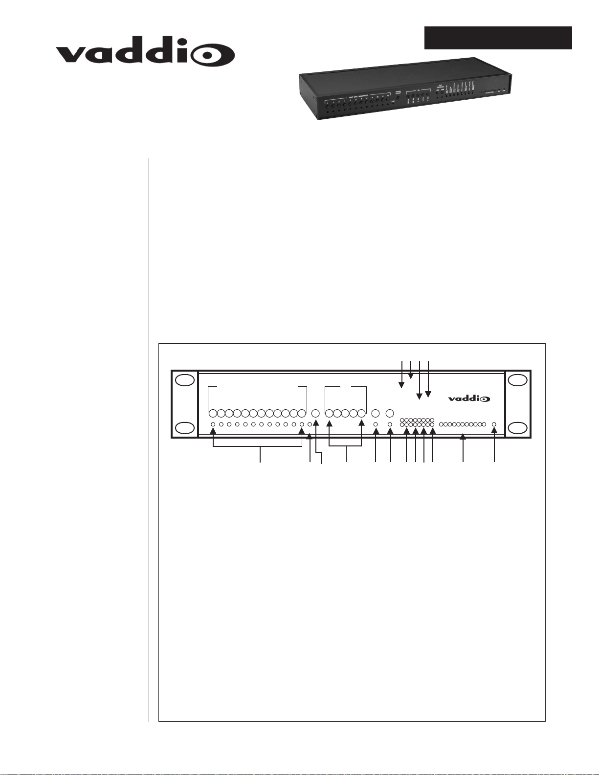
Front Panel
The Vaddio MicVIEW is the microphone switching unit for use in an automated
camera positioning system or in a stand alone operation. The MicVIEW has twelve
microphone inputs with 24V phantom power and +5V status line outputs. Microphones one and two can disable the phantom power and switch between mic-level
and line-level inputs such as cordless, lapel microphones.
• Carefully remove the device and parts from the packing material.
• Set the unit on a flat, solid surface. Unpack and identifiy the following parts:
– One, power supply
– Eighteen, 3-position female 5mm screw terminals
10 8 6 4
INPUT LEVEL ADJUSTMENTS
123456789101112 12345
MASTER
OUTPUT
LINK
EQ
GATE
THRESHOLD
LOW HIGH
PUSH-TO-TALK MODE
INSTRUCTOR PRIORITY
FORCE INSTRUCTION MIC ON
LINK UNITS
INPUT 1 MIC
INPUT 2 PHANTOM POWER
INPUT 2 MIC
INPUT 2 PHANTOM POWER
AUDIO LEVEL
PWR
CLIP
12357913 1112141516
(1) POWER INDICATOR – Green LED indicates that 12 VDC has been connected.
(2) OUTPUT LEVEL – VU Meter indicating volume with CLIP indicator.
(3) INPUT 2 PHANTOM POWER – Toggles Phantom Power on Input 2.
(4) INPUT 2 MIC BUTTON – Toggles Line-Level and Mic Level on Input 2.
(5) INPUT 1 PHANTOM POWER – Toggles Phantom Power on Input 1.
(6) INPUT 1 MIC BUTTON – Toggles Line-Level and Mic-Level on Input 1.
(7) MUTE BUTTON – Mutes microphones 2-12 only.
(8) FORCE INSTRUCTION MIC ON – Mixes microphone 1 with one of the other microphones 2-12 at all
times.
(9) INSTRUCTOR PRIORITY – Gives the instructor the ability to take control from the other microphones.
(10) PUSH-TO-TALK MODE – Toggles between Push-To-Talk and Voice Activated.
(11) HIGH GATE THRESHOLD – Adjusts the threshold at which the Voice Activated function can trigger
from microphone.
(12) LOW GATE THRESHOLD – Adjusts the trigger at which the Push-To-Talk function can be triggered.
(13) EQ – Adjusts the gain of certain frequencies of the output.
(14) MASTER OUTPUT – Adjusts the output gain of the entire MicVIEW system.
(15) LINK LIGHT – Indicates that the system is linked to additional MicVIEW systems.
(16) INPUT LEVLE ADJUSTMENTS – Adjusts the gain of specific microphone inputs.
1
Page 2
MicVIEW
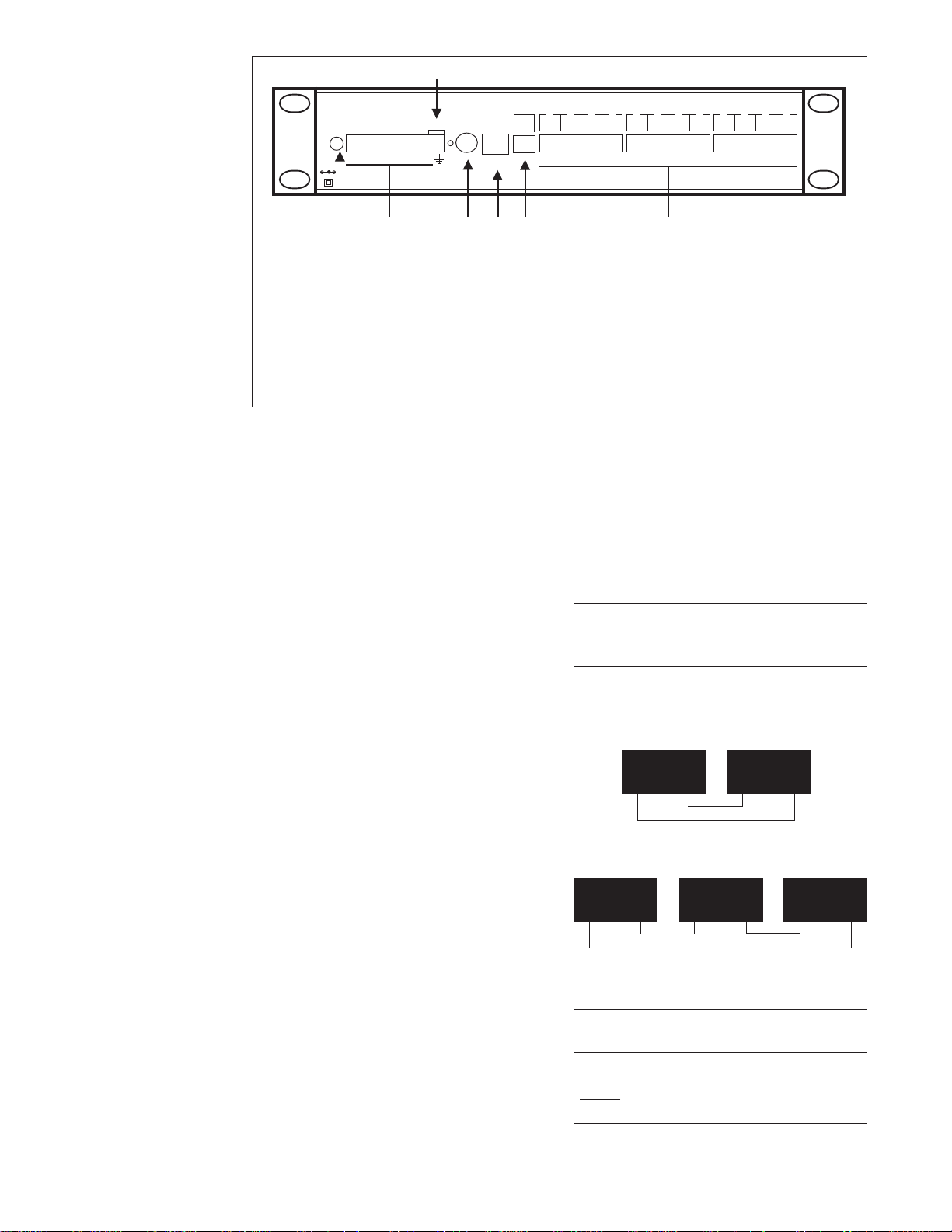
Back Panel
Audio Power By
SOUND CONTROL TECHNOLOGIES
MICROPHONE LOGIC OUTPUT
MUTE
7
LINE
CONTROL
IN OUT
OUTPUT
+ - 5
4 3 2 1
+ - 5
+ - 5
+ - 5
+ - 5
4 3 2 1
+ - 5
+ - 5
+ - 5
+ - 5
+ - 5
4 3 2 1
+ - 5
+ - 5
+ - 5
Setting Up the
MicVIEW
12 VDC
1 2 3 4 5 6 7 8 9 10 11 12
1.5A
C
1
LINK
234
56
MICROPHONE CONNECTORS
(1) PWR – Power Connector.
(2) MICROPHONE LOGIC OUTPUT +5V – status line outputs for indicating which microphone is active.
(3) CONTROL – RS-232 Port for external control of the MicVIEW functions.
(4) LINK IN/OUT – Link Port for connecting multiple MicVIEW units for expanded functionality.
(5) AUDIO LINE OUTPUT – Analog line level output for connection to amplifier or codec for broadcast or
transmission of audio.
(6) MICROPHONES – Twelve 3-Pin connectors for connecting external microphones with 24V phantom
power.
(7) MUTE – Connecting these pins mutes microphones 2-12 and any linked MicVIEW systems.
1.) Connect the (+), (-), and (S)hield pins on microphone Inputs 1-12 to the respec-
tive microphones.
• Microphones 1 and 2 cam be switched to line-level or mic-level with or without
phantom power. Press the Input x Mic button on the front to toggle between miclevel and line-level, and press Input x Phantom Power to toggle phantom power
ON/OFF.
2.) Connect the (+), (-), and (S)heild pins on the Line Output to the line-level on a
codec or amplifier.
• To connect the line output to a phono
cable, connect (+) to the center pin on the
phone cable and the (S) on the MicVIEW
to the negative wire on the phone cable.
DO NOT connect (-) and (S) together as they may
damage the MicVIEW.
WARNING
3.) The MicVIEW units can be linked together by standard Straight-through 6-Pin
RJ-11 cables. The Link light will illuminate when the link is correctly established.
• If two MicVIEW units are to be used to-
gether, connect the Link OUT of the Master system to the Link IN of the slave uni
(see figure at right). Continue by connect-
MASTER SLAVE
LINKINLINK
OUT
LINKINLINK
OUT
ing the Link OUT of the slave unit to the
Link IN of the Master system.
• If multiple MicVIEW units are to be used
together, (up to eight units) connect the
Link OUT of the Master system to the Link
IN of the slave unit (see figure at right).
Continue by connecting the Link OUT of
MASTER SLAVE SLAVE
LINKINLINK
OUT
LINKINLINK
OUT
LINKINLINK
OUT
the slave unit to the LINK IN of the second slave unit. Connect the Link OUT of
the last slave to the LINK IN of the Master
system.
• To Configure as a Slave Unit – Discon-
nect the power. Press and hold Input 2
NOTE: In multiple unit setup only one unit can be
configured as the Master.
Mic/Line and Instructor priority while
reconnecting power.
• To Configure as a Master – Disconnect
the power. Press and hold Input 2
NOTE: Only the Master unit will provide Audio
Output
Phantom Power and Push-To-Talk while
reconnecting power.
continued on next page.
2
Page 3

Setting Up the
MicVIEW
(continued)
4.) If the MicVIEW is to be used with an external system where it is necessary to
know which microphone is active such as the Vaddio ControlVIEW, connect the
Microphone Logic Outputs to the corresponding input connections on the external
device.
5.) Press the Push-To-Talk button to switch between Push-T o-Talk mode (light ON)
and Voice Activated mode (light OFF).
6.) Adjust the Gate thresholds to set the gating for optimum performance by turning
the screw terminal to the left or right to adjust sensitivity. For Push-To-Talk mode,
adjust the Low Gate threshold and for Voice-adtivated mode, adjust the High Gate
threshold.
7.) Adjust the Input Level adjustments to adjust the volume of each microphone.
8.) Adjust the 5-Band Graphic Equalizer for best sound quality for the application by
turning the control to the left or right.
OPERATION
• Voice Activated – Turn on all microphones. Turn OFF Push-To-Talk mode (light
OFF). adjust the Gate Threshold so the ambient noise does not cause a microphone to trigger. One configured for voice activated mode, there is no need for
user intervention. The loudest voice gets control.
• Push-To-Talk (PTT) – Set all microphones to Push-To-Talk (PTT). Turn ON PTT
mode on the MicVIEW (light ON). Adjust the threshold. In PTT mode, a user must
press the PTT button on the microphone and speak into the microphone. When the
user is finished speaking, the user must release the PTT button.
Care and
Cleaning
Operating and
Storage
Conditions
Technical
Specifications
• Do not attempt to take this device apart. There are no user-serviceable parts
inside.
• Keep this device away from food and liquid.
• To clean the exterior, wipe with a damp cloth. Do not use abrasive chemicals.
Do not store or operate this device under the following conditions:
• A temperature above 104
o
F (40oC) or below 32oF (0oC)
• Environments with high humidity
• Dusty environments
• In inclement weather
• Under severe vibration
Analog Audio Input (2) Selectable Microphones/Lines
(10) Microphone Inputs
Phantom Power +24.0 VDC
Analog Audio Output – 1 Output Channel
– Line Level, Variable, 100
Signal to Noise >80dB
(Line Level Throughput)
Frequency Response 20-15,000 Hz
Control Interfaces
Front Panel Push Button Mic/Line, Master/Slave, Switching Mode
Serial Remote Control COMM1 (Rear Panel 9-Pin D, Male) RS-232D
Mixer Link RJ-11-6, Straight Through Cable
Audio Connections Removable 5.5mm Circular Connectors
Power Requirements 12 VDC, 750mA External Plug-in, Universal
AC Input Supply
Weight 3.54lbs/1.6kg
Dimensions
Depth 6.25”/15.9cm
Width 16.75”/42.6cm
Height 1.75”/4.45cm
Power Supply 12 VDC, 750mA
Ω Termination
3
Page 4

Troubleshooting
Problem
Suggestion
The system doesn’t recognize a voice when
someone speaks in
voice activated mode.
The system doesn’t recognize a voice when
someone speaks in
Push-To-Talk mode.
Make sure the microphone is connected to the
MicVIEW and it is on.
Turn OFF the Push-To-Talk mode.
Check Threshold level. Turn the threshold to the
left to reduce sensitvity and to the right to increase
sensitivity.
The MicVIEW uses 24V phantom power. Make sure
the microphones can accept 24V phantom power.
If the microphone is Microphone 1 or Microphone
2, make sure the phantom power is turned ON and
the input is set to Microphone level.
Make sure the microphone is connected to the
MicVIEW and set to Push-To-Talk mode.
Verify the MicVIEW is in Push-To-Talk mode (light
should be ON).
The system seems to
recognize
Make sure the Push-To-Talk button is depressed
when speaking.
Check Threshold level. Turn the threshold to the
left to reduce sensitivity and to the right to increase
sensitivity.
The MicVIEW uses 24V phantom power. Make sure
the microphones can accept 24V phantom power.
If the microphone is Microphone 1 or Microphone
2, make sure the phantom power is turned ON and
the input is set to Microphone level.
Check the Master output. Turn the master output
to the left to decrease volume, to the right to increase volume.
If a microphone is connected to input one or two,
check to see that the Mic level has been selected.
If a device with a line-level output is connected to
input one or two, check to see that Mic level has
been turned OFF.
continued on next page.
4
Page 5

Troubleshooting
Problem
Suggestion
The system doesn’t recognize a voice when
someone speaks in
voice activated mode.
Input one works but the
rest do not.
Audio output quality is
poor, but volume is
good.
Link does not appear
to work.
Each input has an individual gain. Adjust the Input
level adjustment to the left to reduce the gain or to
the right on increase the gain of a specific input.
Make sure the Local Student mute is not enabled.
Adjust the 5-Band equalizer to improve sound
quality.
Make sure to use 6-Pin, RJ-11 cables to connect
the MicVIEW Link. Although the connectors look
like a telephone cord, the system requires six (6)
wires to function.
The Link uses a Master-Slave setup. The
MicVIEWs in the Link must be configured as Slaves
and the main unit must be configured as a Master.
Connect the Link OUT on the secondary MicVIEW
to the Link IN on the primary MicVIEW.
5
Page 6

Declaration of
support@vaddio.com.
Conformity
In accordance with ISO/IEC Guide 22 and BS 7514:
Manufacturer’s Name: Vaddio
This product complies with the requirements of the EMC Directive 89/339/EEC.
Electromagnetic Emissions:
•
CFR 47: 1999 § 15.107 and § 15.109 Class B
• Immunity:
EN 55024 1998
This device complies with Part 15 of the FCC Rules. Operation is subject to the following two conditions.
1.) This device may not cause harmful interference.
2.) This device must accept any interference received, including interference that may cause undesired operations.
Warning: Changes or modifications to this unit not expressly approved by the party responsible for compliance could void the user’s
authority to operate the equipment.
NOTE: This equipment has been tested and found to comply with the limits for a Class B digital device, pursuant to Part 15 of the FCC
Rules. These limits are designed to provide reasonable protection against harmful interference in a residential installation. This equipment generates, uses, and can radiate radio frequency energy and, if not installed and used in accordance with the instructions, may cause
harmful interference to radio communications. However, there is no guarantee that interference will not occur in a particular installation.
If this equipment does cause harmful interference to radio or television reception, which can be determined by turning the equipment off
and on, the user is encouraged to try to correct the interference by one or more of the following measures:
• Reorient or relocate the receiving antenna.
• Increase the separation between the equipment and receiver.
• Connect the equipment into an outlet on a circuit different from that to which the receiver is connected.
• Consult the dealer or an experienced radio/TV technician for help.
Also, a class B digital device meets all requirements of the Canadian Interference-Causing Equipment Regulations.
Warranty
Information
Warranty Information on Hardware* – One (1) year limited warranty on all parts. Vaddio warrants this product against defects in
materials and workmanship for a period of one (1) year from the date of purchase. If Vaddio receives notice of such defects during the
warranty period, Vaddio will either, at its option, repair or replace products which prove to be defective.
Exclusions – The above warranty shall not apply to defects resulting from: improper or inadequate maintenance by customer, customersupplied software or interfacing; unauthorized modifications or misuse; operation outside of the environmental specifications for the
product; use of incorrect power supply; or improper site operation and maintenance.
Obtaining Warranty Service – To obtain warranty service, products must be returned to a service facility designated by Vaddio. Customer shall prepay shipping charges for product(s) returned to V addio for warranty service and V addio shall pay for return of the product(s)
to customer. However , customer shall pay all shipping char ges, duties and taxes for product(s) returned to Vaddio from another country.
Vaddio’s Customer Service – If the camera is still under warranty, Vaddio will test, repair or replace the product(s) without charge. If
the camera is out of warranty, Vaddio will test, then repair the product(s) for the cost of parts and labor. Charges will be estimated by a
technician and confirmed by the customer prior to repair. All camera components must be returned to be tested as a complete unit.
Repair time for all cameras is a maximum of two business days from receiving to outbound shipping. Vaddio will not accept
responsibility for shipment after the camera has left the premises.
Vaddio’s Technical Support – Vaddio’s technicians will determine and discuss with the customer the criteria for repair costs and/or
replacement. Contact Vaddio’s Technical Support through one of these sources: Phone: 763-971-4400; E-mail:
RMA Number (Return Merchandise Authorization Number) –
Before returning a product for repair or replacement, request an RMA number from Vaddio’s Technical Support. Provide the technician
with a return phone number or E-mail and a shipping address. Describe the product(s), provide serial number(s), the reason for repair or
return, and the date of purchase. Include your assigned RMA number on all correspondence with Vaddio. Write your assigned RMA
number on the outside of the box when you return the camera.
Voided Warranty – This warranty does not apply if the Vaddio serial number has been removed or if the product(s) has been disassembled or damaged through misuse, accident, modifications or unauthorized repair.
Shipping and Handling – V addio will not pay for inbound shipping, transportation or insurance char ges, or accept any responsibility for
loss and/or damage from inbound transit. Vaddio requires that all overseas returns are shipped via UPS. Vaddio will pay for outbound
shipping, transportation and insurance charges but will not assume responsibility for loss and/or damage by the outbound freight carrier.
Products Not Under W arranty – Payment arrangements are required before outbound shipping for all products that are out of warranty .
*Vaddio manufactures its hardware products from parts and components that are new or equivalent to new in accordance with industry-
standard practices.
©2003 Vaddio - All Right s Reserved. Reproduction in whole or in part without written permission is prohibited. Specifications and pricing subject to change. MicVIEW and ControlVIEW are
registered trademarks of Vaddio, Inc. All other trademarks are property of their respective owners. Form Number 0105/1-04
9433 Science Center Drive, New Hope, MN • Phone: 800-572-2011, 763.971.4400 • Fax: 763.971.4464 • www.vaddio.com
 Loading...