

Page 1

EC3 Imaging System
Set-Up & Operating
Instructions
UVP, LLC Ultra-Violet Products Ltd.
2066 W 11th Street, Upland, CA Unit 1, Trinity Hall Farm Estate, Nuffield Rd.
Tel: (800) 452-6788 / (909) 946-3197 Cambridge CB4 1TG UK
Fax: (909) 946-3597 Tel: +44(0)1223-420022 / Fax: +44(0)1223-420561
Web Site: www.uvp.com
81-0209-01 Rev C
Page 2

EC3 Imaging System
Table of Contents
Introduction ......................................................................................1
Components ................................................................................... 2
Set-Up and Operating Instructions................................................... 3
Troubleshooting .............................................................................. 6
Repairs and Replacement Parts ..................................................... 7
Technical Assistance....................................................................... 8
Page 3

EC3 Imaging System
Introduction
The EC3 Imaging System is designed specifically for low light and fluorescence imaging and
because of its light-tightness is particularly suitable for chemiluminescent applications. The
special design accommodates a Benchtop Transilluminator on the convenient sliding tray for
easy access. For chemiluminescent applications, the chemi sample tray can be lowered for
sample positioning. Additionally, the darkroom provides users added flexibility due to the
filter wheel and overhead UV.
UVP offers a large selection of cameras with specially designed mounts for securely connecting the camera to the darkroom.
The EC3 Imaging System features:
CCD Camera and Mounting Bracket
The EpiChemi Darkroom may be include
with various camera/bracket options than
shown in the photo. Refer to separate
camera documentation.
Overhead Light
Selector
White Light
365nm UV
254nm UV
Gel Viewer
Emission Filter Wheel Selector
Transillumination
Controls
UV Transilluminator
and Timer
White Light Plate
Master On/Off
Switch
Fold-down
White Light Plate;
Place the Chemi Tray
over the Plate for
viewing blots
UV Transilluminator
Sliding Transilluminator Tray
1
Page 4
EC3 Imaging System
Components
Darkroom Cabinet
The EC3 Imaging System is manufactured of stainless steel construction and fabricated to provide a light-tight chamber. The darkroom
is ready to go with connections to a wall outlet, the camera and camera mount and transilluminator and connection to a computer. As
shown on page 1, components of the darkroom include:
Emission Filter Wheel
The five-position emission filter wheel is designed for viewing many
fluorescent and visible color stains. Rotate the dial to desired filter as
required for your application. The filter wheel is securely mounted into
the darkroom for a clean, protected environment.
Filter Performance
Emission Filter Wheel Control
Overhead Light
UV and white light epi-illumination is built into the darkroom. Select
from the white light, 365nm or 254nm UV.
Transilluminator Tray
The tray slides forward and back for easy access to the transilluminator surface. See transilluminator documentation for specific transilluminator operating instructions.
NOTE: When using the transilluminator with the darkroom door open,
UV exposure safety precautions, including protective eyewear and clothing, must be observed to prevent harmful ultraviolet radiation exposure.
Transillumination Controls
The transilluminator and white light plate are controlled by the darkroom control panel. A timer is included for automatic transilluminator
shutoff.
Overhead Light Control
Sample Platform, White Light
Plate and Transilluminator Tray
Transillumination Controls
2
Page 5
EC3 Imaging System
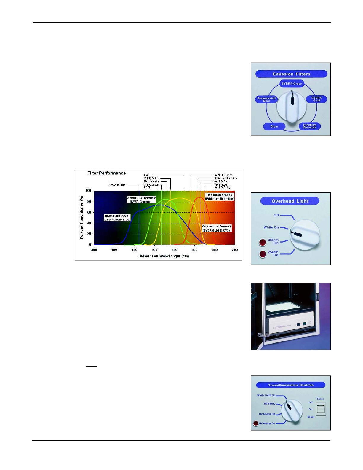
Gel Viewer
The viewer opens for safe viewing of samples. The safety glass allows viewing without exposure to ultraviolet radiation.
Sample Platform and White Light Plate
The Sample Platform folds backwards against the back of the darkroom cabinet. A White Light Plate is built into the platform and is
covered by a cover plate when the white light is not required.
Set-Up and Operating Instructions
Gel Viewer
Sample Platform, White Light
Plate and Transilluminator Tray
NOTE: DO NOT ATTEMPT TO CONNECT ANY WIRING
WHILE THE EQUIPMENT IS CONNECTED TO ANY
POWER SUPPLY.
CAUTION!
Do not install the EC3 Imaging System in places with high moisture,
dust or high temperature.
Do not use any oil or petroleum based cleaner for the cabinet. Use
only mild soap or detergent solution for cleaning. Ensure that the
system is turned OFF during cleaning.
Set-Up
1. Connect the camera and mount to the darkroom as specified in the
camera documentation manual.
2. Connect the power cord to the main power port which is located on the
back-top of the darkroom cabinet.
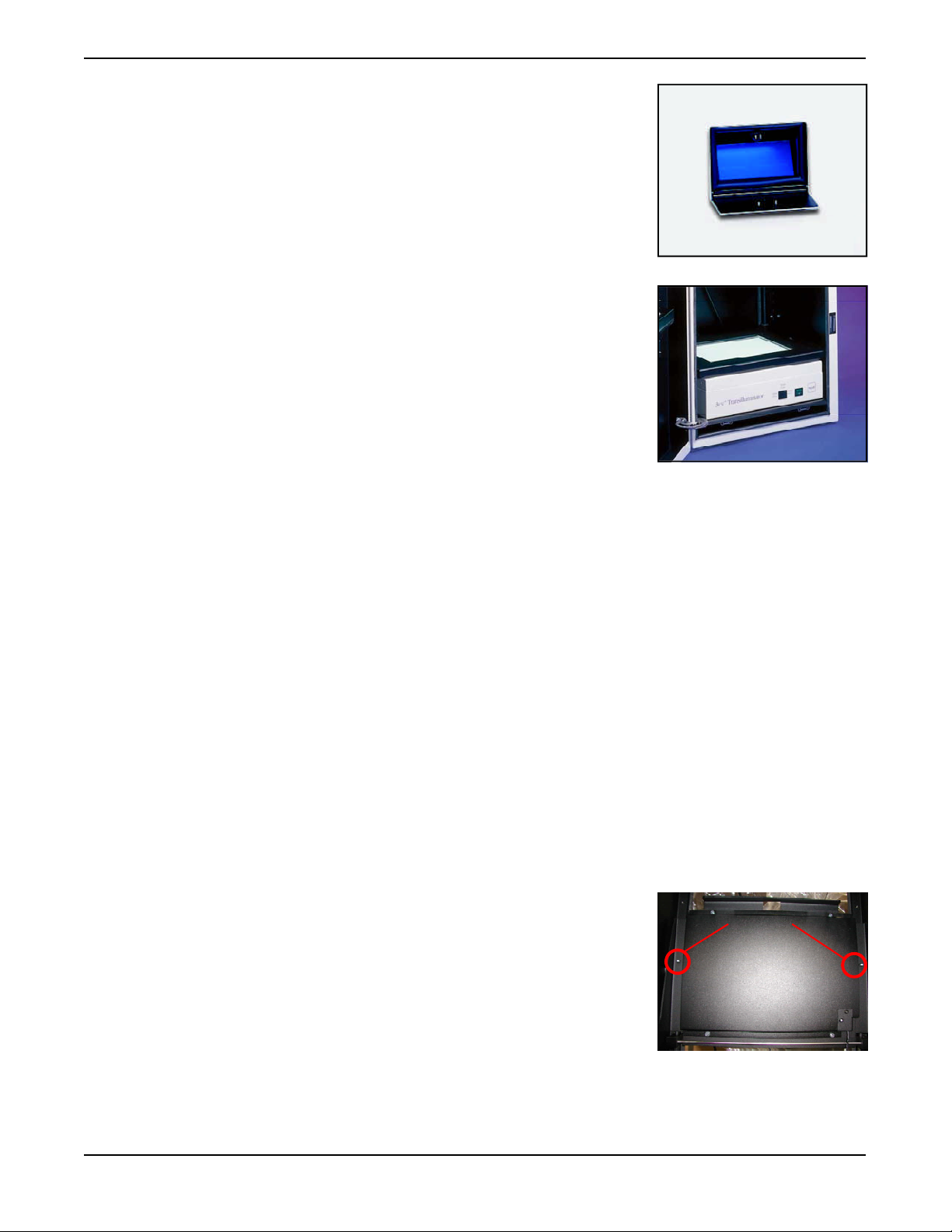
3. For shipping purposes, the chemi tray/white light platform is secured
to the back wall of the darkroom to prevent movement in shipping.
To release the platform, use a Philips head screwdriver to remove the
screws on the two sides of the platform.
Screws
3
Page 6

EC3 Imaging System
Operation
1. Turn on the master power switch on the front of the darkroom cabinet.
Once the power is switched on, power is applied to all internal
components and to the power port for the jumper power cable that
supplies power to the transilluminator.
2. The Transilluminator Control knob has five options:
White Light On - Operates the white light plate located on the platform
UV Safety - Transilluminator safety control switch automatically turns
the transilluminator off when door opens and prevents the user
from exposure to UV
UV Always Off - This button setting puts the transilluminator in Off
mode. Use this switch when the transilluminator is not required
such as when capturing chemi blots.
UV Always On - This setting overrides the safety switch with the
transilluminator always in the on mode. Users should wear
protective clothing and eyewear when the darkroom is in the
Always On mode to prevent exposure to the UV.
Timer Switch - The timer operates the transilluminator. It is
automatically set to shut off at 10 minutes to reduce overexposure to
samples. To override this function, push the timer button to off or
press reset to start the timer again.
3. The Overhead Light control knob has four options for providing
overhead diffused 254 and 365nm UV and fluorescent white light for
uniform epi-illumination.
Off - Place the overhead light switch in the Off mode when not using
the darkroom for applications requiring epi-illumination.
Transillumination Controls
Overhead Light Control
White - Overhead white light illuminates when “white” is selected.
365nm and 254nm - When either ultraviolet wavelength is selected,
the red light will illuminate to alert the user that the light is in operation.
The overhead lights are designed to automatically turn off when the
darkroom door is open.
4. The Emission Filter Wheel is designed with five-positions for
viewing samples with the 400 - 655nm emission filters. Use the
interface center to select from:
Blue (400-600nm)
Green (515-570nm)
Gold (485-655nm)
Red (570-640nm)
Clear (empty)
Emission Filter Wheel Control
4
Page 7
EC3 Imaging System
5. The Transilluminator Tray accommodates a Benchtop UV Transilluminator. The tray moves forward or back for easy access to the
transilluminator surface.
NOTE: When using the transilluminator with the darkroom door open,
UV exposure safety precautions, including protective eyewear and
clothing, must be observed to prevent harmful ultraviolet radiation
exposure.
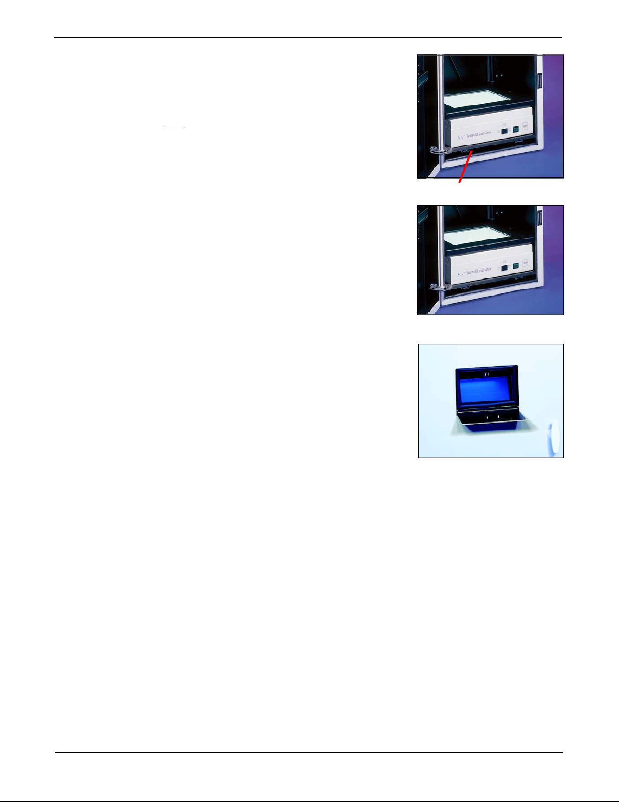
6. The Sample Platform folds backwards against the back of the
darkroom cabinet. Pull the platform down into a horizontal position
as shown in the picture. The sample platform is designed for use
when transillumination is not required. The platform provides a
surface for placement of chemiluminescent blots with minimum
background noise interference. the platform adjusts to various
heights. Slide the platform up or down using two hands.
When white light is required, position the sample platform at the
desired height and remove the cover plate to expose the white light.
7. The Gel Viewer has a pressure-sensitive clasp. Press firmly to
open the viewer. The glass is UV blocking while providing a clear
view to the transilluminator or platform surface for visibility of samples
without opening the door.
Transilluminator Tray
Sample Platform and White Light
Plate
Gel Viewer
5
Page 8

EC3 Imaging System
Troubleshooting
No power to darkroom cabinet.
1. Recheck main power cord connections to the both the dark-
room and the wall power (surge protector).
2. Check the fuse located on the main power port. If the darkroom
continues to blow fuses, call UVP Technical Support Department.
Transilluminator will not turn on.
1. Check to make sure the darkroom cabinet’s door is completely
closed. There is a UV exposure safety cut-off switch that turns
the transilluminator off when the darkroom cabinet’s door is
opened.
2. Check the darkroom cabinet’s main power switch is lit. If not,
refer to “No power to darkroom cabinet” above.
3. Be sure the transilluminator switch is on. When the switch on
the transilluminator is lit green, the unit is receiving power!
4. Be sure the transilluminator control switch on the darkroom’s
front panel is selected to either “safety switch” or “always on.”
5. Call UVP Technical Support Department with any technical ques-
tions.
6
Page 9
EC3 Imaging System
Repairs and Replacement Parts
For technical assistance, contact UVP’s offices listed in the
Technical Assistance section. To order replacement parts, contact
UVP’s Customer Service Department at the same locations.
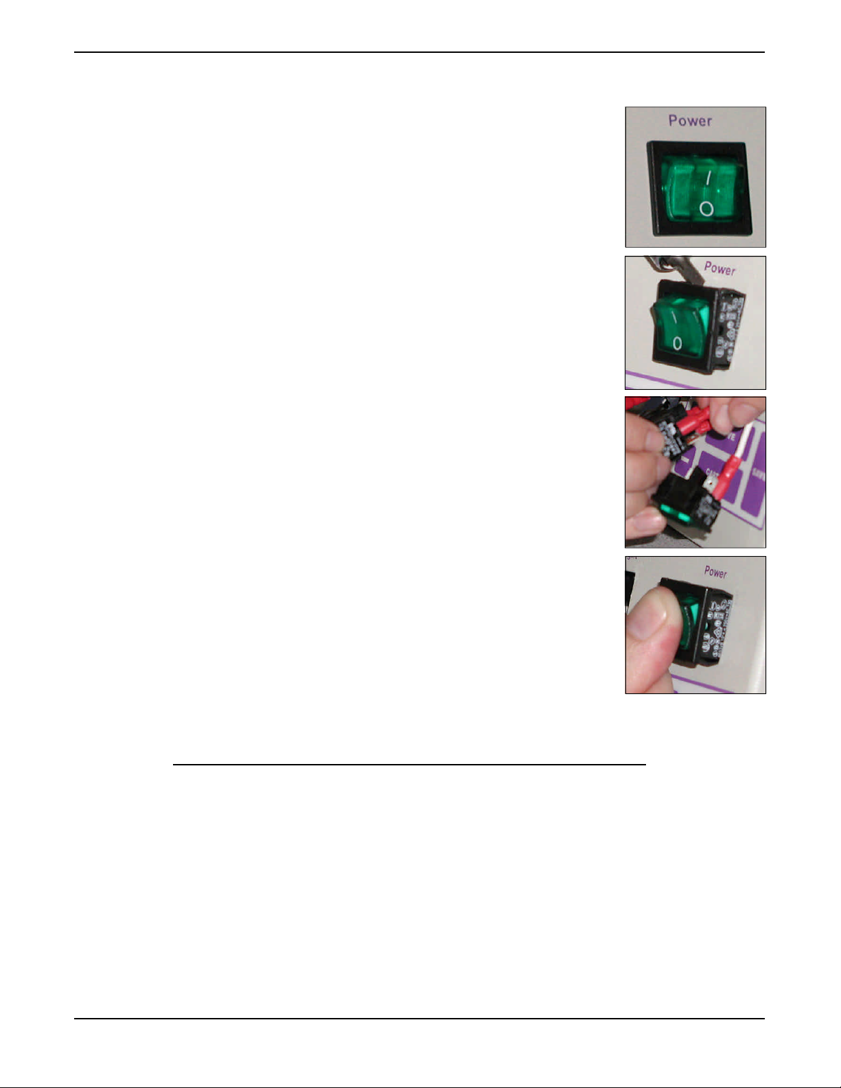
Switch Replacement Procedures
The darkroom and transilluminator use the same power switch. To
replace the power switch in the darkroom or transilluminator:
1. Unplug the darkroom and/or transilluminator from the power
source prior to removing the power switch.
2. To remove the power switch from the unit, use a thin flat head
screw driver to pry the switch out from housing. Be careful not to
scratch the paint of the darkroom or transilluminator in the process.
3. Once the switch is removed, you will see a number of connector
wires plugged into the back of it. Normally there are two black
and two white wires, with some exceptions. Pull one wire out of
the old switch and put it into the same connector location on the
new switch. Continue this process for each wire until all are
connect to the new switch.
Switch Replacement
Procedures
4. Push the new switch back into its position.
Replacement Parts
To order replacement parts for the EC3 Imaging System, contact
UVP’s offices. Contact information is listed on the next page.
Part Description Part Number Qty.
Tube, 8 watt, fluorescent, cool white 34-0056-01 2
Tube, 8 watt, 365nm UV longwave 34-0006-01 2
Tube, 8 watt, 254nm UV germicidal 34-0007-01 2
Cable and connector wall plug, 115V and 100V 58-0085-01 1
Cable and connector wall plug, 230V 58-0085-03 1
Power Switch 53-0024-01 1
7
Page 10

EC3 Imaging System
Technical Assistance
UVP offers technical support for all of its products. If you have any questions about the product’s use,
operation or repair, please call or fax UVP Customer Service or Technical Support at the following:
If you are located in North America, South If you are in Europe, Africa, the Middle East
America, East Asia or Australia: or Western Asia:
Call (800) 452-6788 or (909) 946-3197 and Call +44(0) 1223-420022 and ask for BioImaging
ask for BioImaging Systems Technical Support. Systems Technical Support. Support is available
Tech Support assistance is available during during regular business days, between 8:00am
regular business days, between 7:00am and and 5:30 pm UK time.
5:30 pm PST.
E-Mail your message to: E-Mail your message to
techsupport@uvp.com uvp@uvp.co.uk
Fax your questions to: Fax your questions to:
(909) 946-3597 +44(0)1223-420561
Write to: Write to:
BioImaging Systems Technical Support BioImaging Systems Technical Support
UVP, LLC Ultra-Violet Products Ltd.
2066 W. 11th Street Unit 1, Trinity Hall Farm Estate, Nuffield Road
Upland, CA 91786 USA Cambridge CB4 1TG UK
NOTE! A Returned Goods Authorization (RGA) number must be obtained from UVP’s
Customer Service Department prior to returning any product to UVP.
Products available from UVP
VisionWorksLS Image Acquisition and Analysis Software
Ultraviolet Transilluminators
UV/White Light Transilluminators
Visi-Blue Transilluminators and Plates
White Light Transilluminators and Plates
Gel Tools
UV Crosslinkers
UV Viewing Cabinets
UV Lamps
Ultraviolet Intensity Meters
Hybridization Ovens
PCR Workstations
UV Incubator
8
 Loading...