

Page 1
DigiDoc-It® Imaging System
Installation and User Instructions
UVP, LLC Ultra-Violet Products Ltd.
2066 W. 11th Street Unit 1, Trinity Hall Farm Estate
Upland, CA 91786 Nuffield Road, Cambridge CB4 1TG UK
Phone: (800) 452-6788 / (909) 946-3197 Phone: +44(0)1223-420022
Fax: (909) 946-3597 Fax: +44(0)1223-420561
Web Site: www.uvp.com
81-0218-01 Rev L
Page 2
DigiDoc-It Imaging System 2
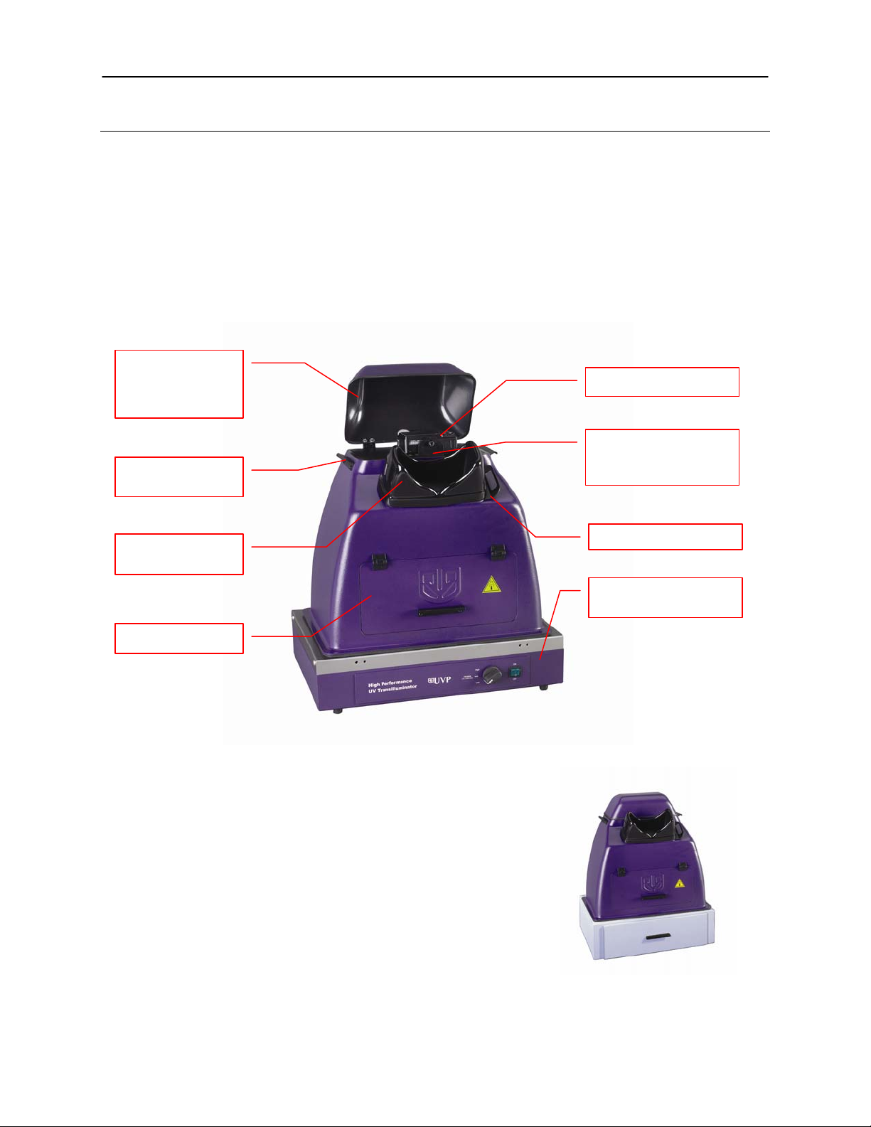
Camera cap
camera
Handles for carrying
the hood
Gel Viewport
Window
Hood access door
DigiCam 125 camera
Ethidium Bromide Filter
Viewport cover
High Performance UV
Transilluminator
Introduction
The DigiDoc-It Imaging System is a basic gel imaging system designed to fit over any of UVP’s optional High
Performance UV Transilluminators or optional Benchtop UV Transilluminator and drawer combination. The
system combines:
Hood enclosure
DigiCam 125 digital color camera
Ethidium Bromide (EtBr) Filter
Doc-It
UV transilluminator or drawer assembly (optional). Transilluminator instructions are provided in a
enclosure for
access to the
®
LS Acquisition Software (refer to software manual for installation)
separate manual.
is located inside the
hood under the camera
Hood Enclosure
The DigiDoc-It hood enclosure includes a cap to reduce ambient and
reflective light when taking pictures. The soft rubber viewport window
allows researchers to view samples prior to capturing images. The slide
closure under the viewport minimizes ambient light when taking
pictures. The lightweight door provides access to the enclosure interior
for placement of samples on the transilluminator surface.
The DigiDoc-It drawer fits under the hood enclosure and accommodates
a compact Benchtop UV Transilluminator.
DigiDoc-It with drawer
Page 3
DigiDoc-It Imaging System 2
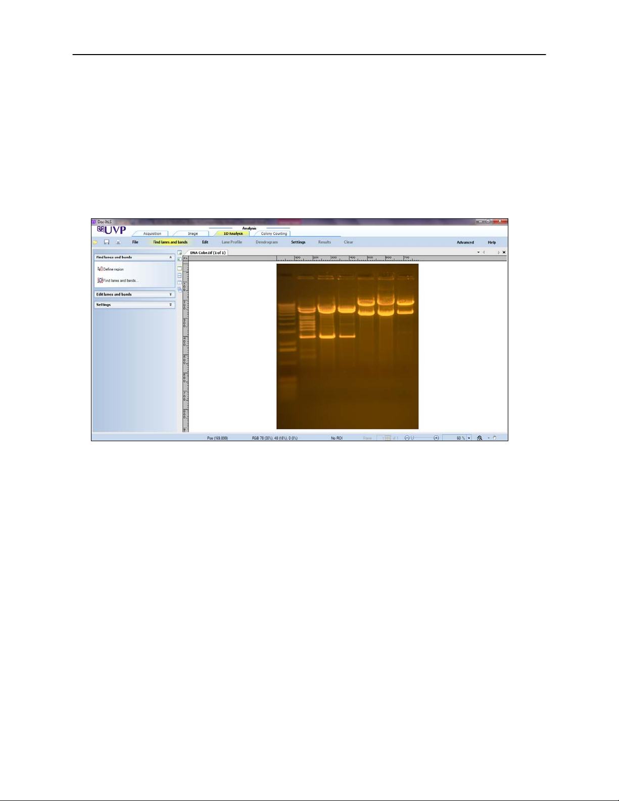
Doc-ItLS Acquisition Software
Camera & UV Filter
The digital color camera includes a zoom lens.
The EtBr filter, orange-colored UV blocking band pass filter, is installed inside the hood at the UVP factory. The
filter is used to absorb UV and IR radiation from the transilluminator and to enhance the orange/pink bands
generated by Ethidium Bromide stained gels. The filter can be removed when imaging non-fluorescent media
(protein gels, colony plates, etc.) in order to produce brighter images.
Doc-ItLS Software
The Doc-ItLS software loads onto the user’s existing computer. The software controls the camera acquisition
functions as well as enhancement and reporting features. For information on installation and use of the software,
refer to the Doc-ItLS Software help files.
UV Transilluminator
An UV transilluminator may be shipped with the system. The transilluminator includes an ultraviolet blocking
cover and the cover should be removed when the transilluminator is used with the system. Refer to the
Transilluminator manual for separate instructions.
Operating System Requirements
• Windows 7, Vista or XP SP2 or later
• Internet Explorer 6.0 or higher [To locate the version of Internet Explorer, open Internet Explorer and
click on Help->About Internet Explorer]
• Intel Pentium Processor or equivalent, 1.6 GHz or higher
• 1 GB of RAM or greater
• 200 MB of available hard disk space for the program, more for data
• CD-ROM drive
• One Universal Serial Bus (USB) for connecting the camera
• Color monitor, supporting at least 1024 x 768 resolution and 16-bit or better colors; 24-bit or 32-bit color
is strongly recommended
NOTE: For 21 CFR Part 11 support functionality, the computer partition must be formatted with NTFS. Refer to
the Doc-ItLS software manual for instructions.
Page 4
DigiDoc-It Imaging System 3
High Performance 2UV Transilluminator
DigiDoc-It Drawer
(may be different color)
System Setup
DO NOT ATTEMPT TO CONNECT ANY WIRING W HILE THE EQUIPMENT IS CONNE CTED TO ANY POWER
SUPPLY.
CAUTION: Do not install the system in places with high moisture, dust or high temperature. Do not use any oil or
petroleum based cleaner for the cabinet. Use only mild soap or detergent solution for cleaning. Ensure that the
system is turned OFF during cleaning. Keep the equipment away from motors or other large magnetic equipment
apparatus.
Place the Hood on top of the Transilluminator
The Hood Enclosure can be used with a High Performance UV Transilluminator. When using a Benchtop
Transilluminator, the optional drawer is required.
CAUTION: All UVP Transilluminators are powerful sources of UV radiation that will cause damage to unprotected
eyes and skin. Before operating any unit, be sure all personnel in the area are properly protected. UV Blocking
Eyewear is highly recommended and should be worn. Refer to the Accessories section of this manual for UV
Blocking Eyewear.
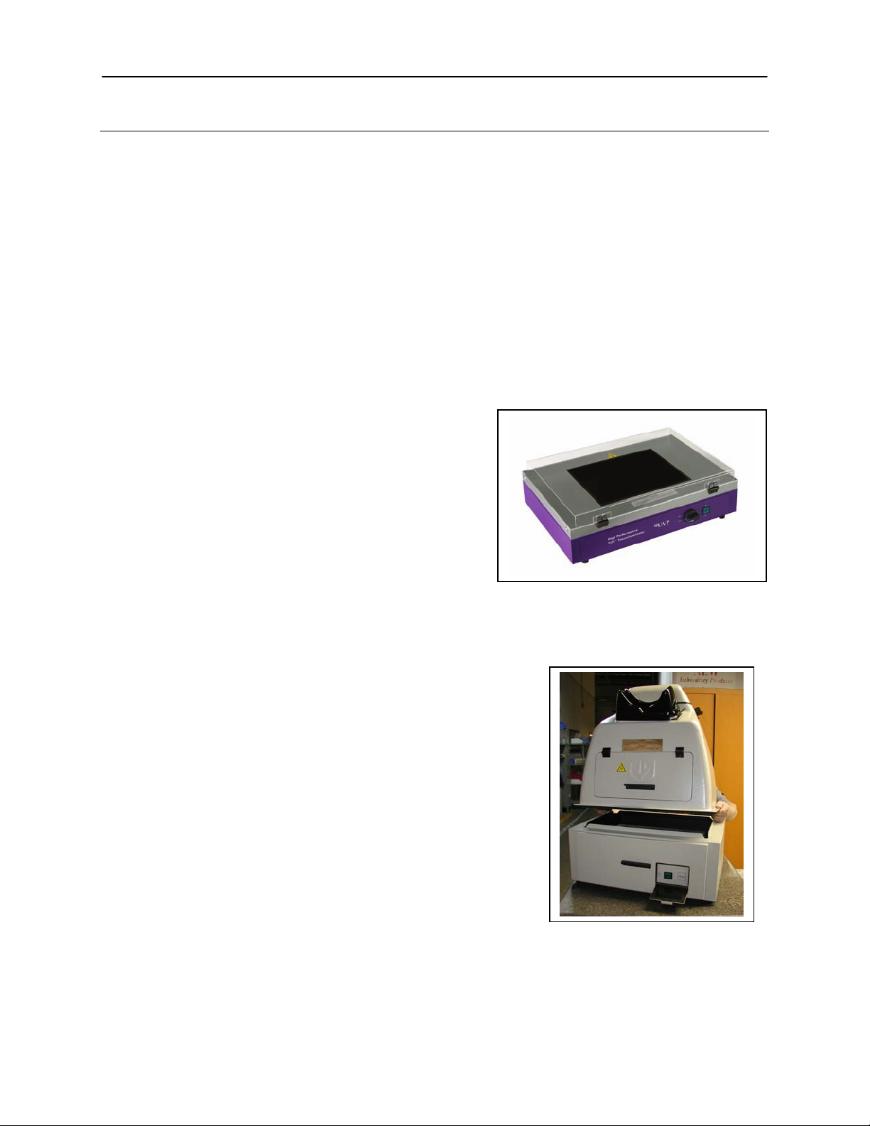
High Performance Transilluminator
1. Remove the UV blocking clea r c over from the
Transilluminator.
2. Position the transilluminator so the switch is facing
the user.
3. Connect the power cord to the back of the
transilluminator and connect the plug to a power
source.
4. Place the Hood Enclosure on top of the
Transilluminator surface so that the filter glass is
covered.
Benchtop Transilluminator and Drawer
1. Remove the UV blocking clear cover from the Transilluminator.
2. Place the Benchtop Transilluminator into the drawer.
3. Connect the power cord to the back of the transilluminator and
push the plug through the access hole in the back of the
drawer.
4. Connect the plug to the power source.
5. Access to the transilluminator switch is via the access port on
the front of the drawer.
6. Place the DigiDoc-it hood over the drawer.
Camera Assembly
(shown with UV blocking cover)
1. The camera will be installed in the DigiDoc-It hood at the UVP
factory.
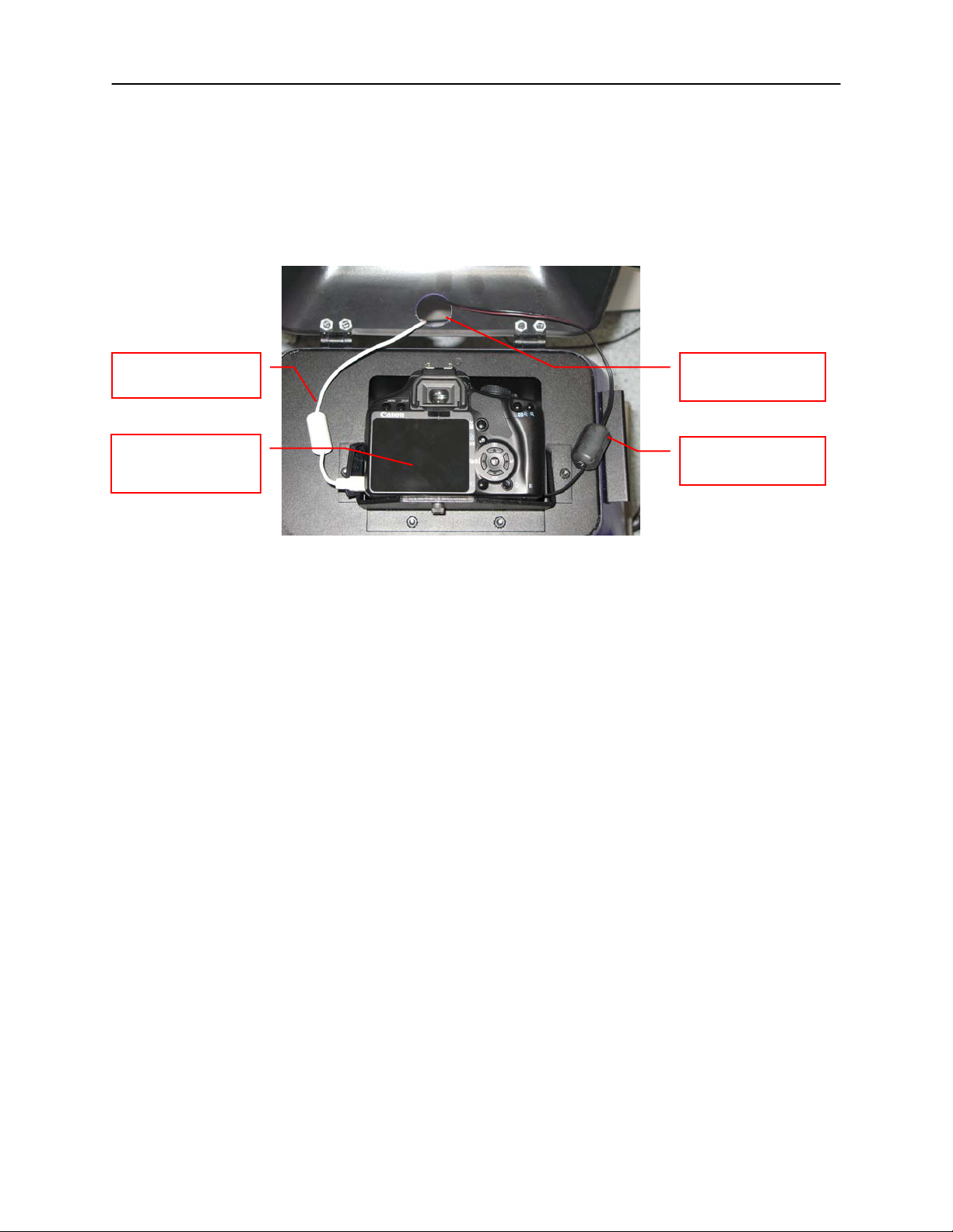
2. To connect the power cable to the camera, thread the
camera’s power cable through the round notched hole from the
back of the camera cap and plug it into the camera as shown.
Page 5
DigiDoc-It Imaging System 4
Note: The Ethidium Bromide filter is installed inside the hood enclosure at the UVP factory. If the filter needs
Hole in DigiDoc-It
Power supply cable,
USB cable, plug into
computer
DigiCam 125 camera
than shown)
3. To connect the USB cable to the camera, thread the camera’s USB cable through the round notched
hole from the back of the camera cap and plug into the camera. Leave the other end unplugged until
ready to load the software.
4. Plug the camera’s power supply into a wall outlet or surge-protector receptacle.
to be replaced, turn the hood upside down. Loosen screws and slide the filter into the filter tray. Retighten
screws and place the hood upright.
hood for cables
(may appear different
plug into wall outlet
Install the Doc-ItLS Software
NOTE: The following provides a brief instruction for installing the software. For additional instruction on using the
software, refer to the Doc-ItLS help files.
1. Insert the CD into the CD-ROM drive. The installation program should automatically start. If the
installation program fails to start, navigate to the CD-ROM drive and double-click setup.exe to launch
Doc-It.
2. Follow instructions from the Wizard screens as they appear, clicking Next, Accept or Finish as
appropriate.
3. If prompted to restart the computer, click No.
4. Restart the computer by choosing Restart from the Windows Start menu.
5. Double click onto the UVP icon on the desktop.
6. Activate the software by choosing On the fly activation if connected to the internet. Complete all the
required information on the form and fill in the Serial Number (located on the CD). Click onto Get
Activation No. and then click onto Activate when the Activation Number appears in the box.
7. Close the software.
NOTE: If not connected to the Internet, call technical services at (800) 452-6788 or (909) 946-3197 to complete
the activation process.
Page 6

DigiDoc-It Imaging System 5
NOTE: It is recommended to only connect the camera to the computer while the camera is off.
Connect the Camera to the Computer
1. Connect the USB cable from the camera to the computer.
2. Turn the camera on and select A-DEP on the camera dial.
NOTE: Do not use the Doc-ItLS software while the camera dial is set to movie mode as doing
so may result in an error.
Set camera to A-DEP
Connect to Doc-ItLS Software
1. Open the Doc-ItLS software. The software should automatically identify the camera. The camera
control window should be active and ready to capture images.
Page 7
DigiDoc-It Imaging System 6
System Operation
Loading Gels into the Darkroom Hood
1. Turn Off the UV Transilluminator.
2. Open the darkroom door.
3. Place the sample to be imaged in the center of the transilluminator filter glass.
4. Close the darkroom door.
5. Turn On the transilluminator.
Note: It is important to minimize the light source exposure to the sample. Turn off the light source as soon as the
image is captured.
View a Sample Prior to Capture
1. Open the Viewport Window on the hood by sliding the cover to the right.
2. After visually checking that the sample is loaded correctly, close the Viewport Window. Otherwise, light
from the viewport will interfere with the capturing process.
Camera Operation
NOTE: Do not use the Doc-It software while the camera dial is set to movie mode as doing so may result
in an error.
1. To use the camera, open the camera cap on top of the hood.
2. To capture in automatic mode, set the camera mode dial button to A-DEP. (Automatic mode is
recommended for a quick image capture)
3. Close and secure the camera cap on the hood.
Note: If the camera is off when starting Doc-It softwar e, a message stat ing t hat the applic a tion can not find a
camera will appear. To remedy this, turn the camera on and click Retry.
Software Operation
NOTE: Do not use the Doc-It software while the camera dial is set to movie mode, as doing so may result
in an error.
1. Ensure that the camera mode is set to A-DEP for auto mat ed capt ure.
2. Open the Doc-ItLS software.
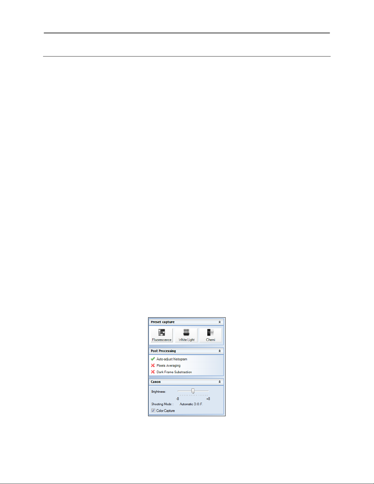
3. A window displaying the camera options should appear as pictured below. If not, click on the Acquisition
Action tab and then on the Camera menu button.
Camera Control Window
Page 8
DigiDoc-It Imaging System 7
4. To take images in color, ensure that the Color Capture box is checked.
5. Select Preview at the top of the software to preview the image.
6. While in preview mode, the Brightness slider can be adjusted to brighten dark images.
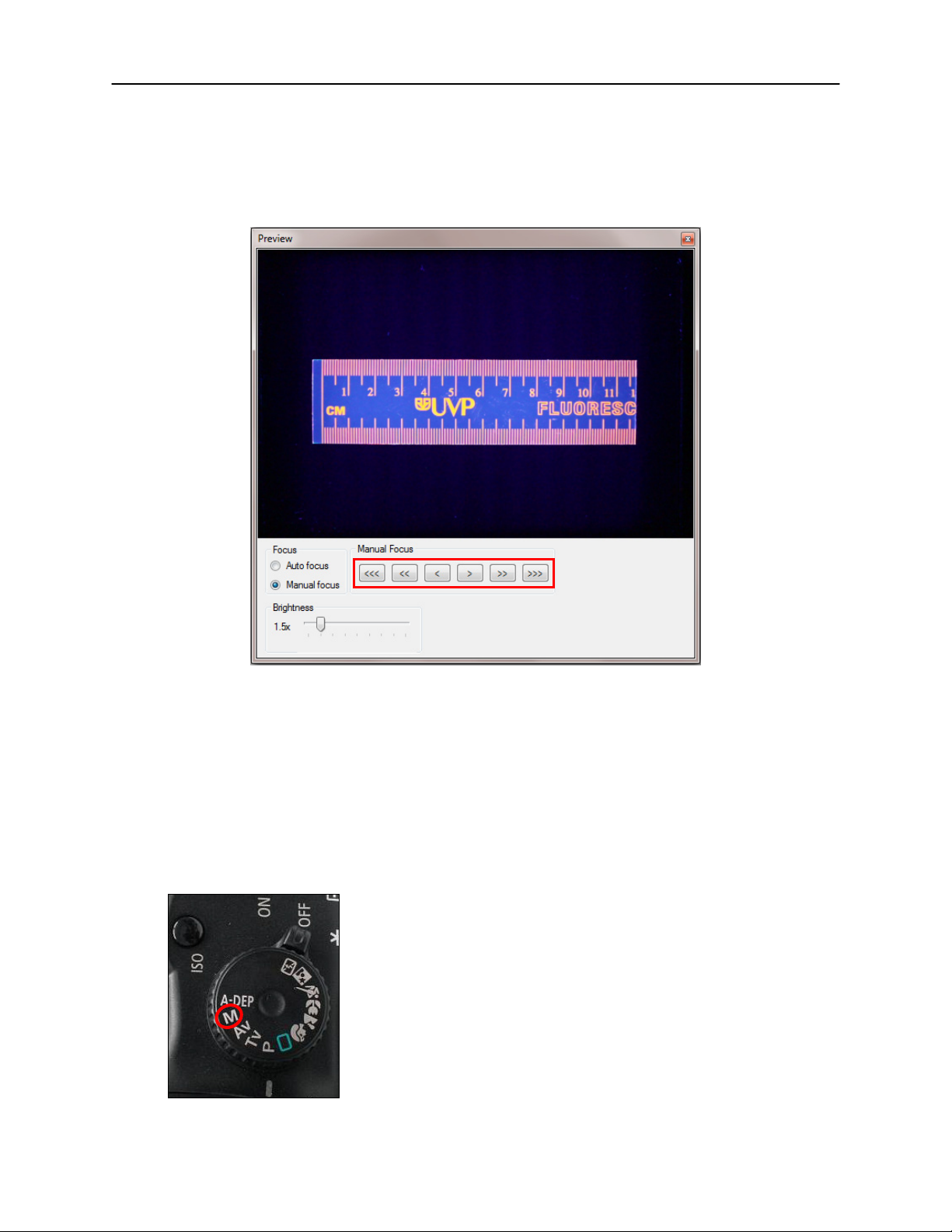
7. The user may adjust the focus manually to enhance the appearance of the previewed image. Click the
Manual focus radio button on the Preview window, then use the left and right arrows (shown in the red
box, below) to adjust the focus settings.
Preview Window with Manual Focus
8. When satisfied with the previewed image, select Capture at the top of the software.
Optional Camera Setup (Image Acquisition)
If operating the camera in automatic mode is not sufficient for the application, try utilizing the manual mode to
gain additional camera control.
1. Access the camera and turn the camera dial to M, the next position on the dial. (The dial is preset to A-
DEP and will only turn in one direction.)
Set camera to M
Page 9

DigiDoc-It Imaging System 8
2. A new camera window appears with additional options:
Camera Control in Manual Mode
3. Select the desired options for an enhanced image. See the camera manual for detailed descriptio ns of
options.
4. Select Capture at the top of the software.
Page 10

DigiDoc-It Imaging System 9
If residing in North America, South
If residing in Europe, Africa, the Middle
Call (800) 452-6788 or (909) 946-3197,
Call +44(0) 1223-42002, and ask for
E-mail your message to:
E-mail your message to: uvp@uvp.co.uk
Fax Customer Service, and send it to (909)
Fax Customer Service, and send it to: +44(0)
Write to: UVP, LLC 2066 W. 11th Street,
Write to: Ultra-Violet Products Ltd
Service Procedures
Return Procedure
A Returned Goods Authorization (RGA) number must be obtained from UVP Customer Service before returning
any product.
Replacement Parts and Accessories
Accessories are available for use with the DigiDoc-It Imaging Systems. Contact UVP’s offices at the telephone
numbers below for replacement parts for DigiDoc-It equipment. For transilluminator replacement parts, refer to
the separate manual for the transilluminators included with your shipment.
Description Part Numbers
Drawer (for Benchtop Transilluminators) 98-0068-01
Doc-ItLS Analysis Software 97-0185-02
Thermal Printer, Digital (115/230V) 89-0069-06
Thermal Printer, Digital (230V) 89-0069-07
Thermal Printer, Digital (230V for Europe) 98-0069-15
Thermal Paper, 4 rolls (800 images) 89-0038-01
Thermal paper, 16 rolls (3200 images) 89-0038-04
Thermal Paper, 40 rolls (8000 images) 89-0038-05
UV to White Light Converter Plate (21x26cm) 38-0191-01
UV to White Light Converter Plate (20x40cm) 38-0191-02
Visi-Blue Converter Plate (21x26cm) 38-0200-01
Visi-Blue Converter Plate (20x40cm) 38-0200-02
Filter, 50mm, sq., SYBR Green and EGFP 38-0219-01
Filter, 50mm, sq., Ethidium Bromide 38-0220-01
Technical Assistance
UVP offers technical support on all of its products. If there are questions about the product’s use, operation or
repair, please contact our offices at the locations below, or go to UVP’s web site and click the Tech Support >
BioImaging Systems.
America, East Asia or Australia:
and ask for Customer Service during
regular business days, between 7:00 am
and 5:00 pm, PST.
techsupport@uvp.com
946-3597
Upland, CA 91786 USA
East of Western Asia:
Customer Service during regular business
days between 9:00 am and 5:30 pm.
1223-420561
Unit 1, Trinity Hall Farm Estate, Nuffield Road,
Cambridge CB4 1TG UK
Page 11

DigiDoc-It Imaging System 10
Warranty
UVP's products are guaranteed to be free of defects in materials, workmanship and manufacture for one (1) year
from date of purchase. Consumable and disposable parts including, but not limited to tubes and filters, are
guaranteed to be free from defects in manufacture and materials for ninety (90) days from date of purchase.
Transilluminators carry a two (2) year warranty from date of purchase. If equipment failure or malfunction occurs
during the warranty period, UVP shall examine the inoperative equipment and have the option of repairing or
replacing any part(s) which, in the judgment of UVP, were originally defective or became so under conditions of
normal usage and service.
No warranty shall apply to this instrument, or part thereof, that has been subject to accident, negligence,
alteration, abuse or misuse by the end-user. Moreover, UVP makes no warranties whatsoever with respect to
parts not supplied by UVP or that have been installed, used and/or serviced other than in strict compliance with
instructions appearing in this manu al.
In no event shall UVP be responsible to the end-user for any incidental or consequential damages, whether
foreseeable or not, including but not limited to property damage, inability to use equipment, lost business, lost
profits, or inconvenience arising out of or connected with the use of instruments produced by UVP. Nor is UVP
liable or responsible for any personal injuries occurring as a result of the use, installation and/or servicing of
equipment.
This warranty does not supersede any statutory rights that may be available in certain countries.
DigiDoc-It and Doc-It are registered trademarks of UVP, LLC
 Loading...