

Page 1

ColonyDoc-It™ Imaging Station
Instruction Manual
UVP, LLC Ultra-Violet Products Ltd.
2066 W 11th Street, Upland, CA 91786 Unit 1, Trinity Hall Farm Estate
Tel: (800) 452-6788 / (909) 946-3197 Nuffield Road, Cambridge CB4 1TG UK
Fax: (909) 946-3597 Tel: +44(0)1223-420022 / Fax: +44(0)1223-420561
Email: info@uvp.com Email: uvp@uvp.co.uk
Web site: uvp.com
81-0294-01 Rev. E
Page 2

ColonyDoc-It Imaging Station 2
Page 3

ColonyDoc-It Imaging Station 3
END USER LICENSE AGREEMENT
PLEASE READ THE FOLLOWING AGREEMENT CAREFULLY
This Agreement is between UVP, LLC of 2066 West 11th Street, Upland, California 91786 (hereinafter “Licensor”) and the
end user of UVP software (hereinafter “Licensee”).
Licensor has developed and offers to Licensee on a non-exclusive basis pursuant to the terms and conditions set forth
hereinafter, the following software, including related copyrighted instructional materials, (collectively referred to hereafter as
“The Software”):
DOC-IT COLONY SOFTWARE
The terms of this Agreement apply without regard for the method by which the Software is acquired by Licensee. While the
most common medium for acquiring the Software from Licensor is by CD-ROM, the Software may, in some instances, be
acquired by download; from a Licensor thumb drive acquired from Licensor; from a CD ROM acquired from Licensor from a
network location; or may be pre-installed on the Licensee‟s computer.
By using the Software, you are agreeing to be bound by all terms of this License. If you do not agree to the terms of the
License, you are not authorized to use the Software in any manner.
LICENSE
In consideration of payment of the License fee, which is a portion of the price you paid, the software, including any images
incorporated in or generated by the software, and data accompanying this License and related documentation are licensed
(not sold) to you by Licensor. Licensor does not transfer title to the Software to you; this License shall not be considered a
“sale” of the software and Licensor retains full and complete title to the Software and all intellectual and industrial property
rights therein. It is to be understood that this non-exclusive and personal License only gives you the right to use and display
the software. You must treat the software like any other copyrighted material. You may not copy the Software or the written
material accompanying the software without the express written consent of Licensor.
RESTRICTIONS
The Software contains copyrighted materials, trade secrets, and other proprietary material. You may not re-sell, decompile,
reverse engineer, disassemble or otherwise reduce the Software to a human-perceivable form. Except as provided for in
this License, you may not copy, modify, network, rent, lease, or otherwise distribute the Software; nor can you make the
Software available by “bulletin boards”, on-line services, remote dial-in, or network or telecommunications links of any kind;
nor can you create derivative works or any other works that are based upon or derived from the Software in whole or in part.
You may not transfer the license rights to the Software to another party.
TERMINATION
This License is effective until terminated by either party. You may terminate this License at any time by returning the
Software to Licensor or destroying any permanent form of the software and all related documentation and all copies and
installations thereof, whether made under the terms of this License or otherwise. This License will terminate immediately
without notice from Licensor if you fail to comply with any provision of this License. Upon termination, you must destroy or
return to Licensor any permanent form of the software and related documentation.
LIMITED WARRANTY AND DISCLAIMER
Licensor warrants the software and related documentation to be free from defects in materials and workmanship, under
normal use for a period of ninety (90) days from the date of purchase as evidenced by a copy of the sales receipt or packing
slip. Licensor‟s entire liability and licensee‟s exclusive remedy will be replacement of the defective software and related
documentation or refund of the purchase price (at licensor‟s election) upon return of the software and related documentation
to licensor with a copy of proof of purchase. This warranty gives you specific legal rights and you may also have other rights
which vary from jurisdiction to jurisdiction. You expressly acknowledge and agree that use of the software is at your sole risk
after the ninety (90) days. The software and related documentation are provided without warranties and/or conditions of any
kind either express or implied, except as provided above. Licensor expressly disclaims all other warranties and/or
conditions, express or implied, with respect to software and related documentation including, but not limited to, the implied
warranties and/or conditions of merchantability and fitness for a particular purpose. Licensor does not warrant that the
functions contained in the software will be uninterrupted or error-free, or that defects in the software will be corrected after
the ninety (90) days. Furthermore, after the ninety (90) days, licensor does not warrant or make any representation
regarding the use or the results of the use of the software and related documentation in terms of their correctness, accuracy,
reliability, or otherwise. The limitations of liabilities described in this section also apply to the third party suppliers of
materials used in the software. No oral or written information or advice by licensor or by representatives of licensor shall
Page 4

ColonyDoc-It Imaging Station 4
create warranties, and/or conditions, or in any way increase the scope of this limited warranty. Licensee assumes the entire
cost of all necessary servicing, repair or correction after the ninety (90) days. Some jurisdictions do not allow the exclusion
of implied warranties, so the above exclusion may not apply to you.
LIMITATION OF LIABILITY
Under no circumstances, including negligence, shall licensor be liable for any special or consequential damages that result
from the use of, or the inability to use, the software or related documentation, even if licensor or authorized representative of
licensor has been advised of the possibility of such damages. Some jurisdictions do not allow the limitation or exclusion or
liability or consequential damages, so the above limitations or exclusion may not apply to you. In no event shall licensor‟s
total liability to you for all damages, losses, and causes of action (whether in contract, tort (including negligence) or
otherwise) exceed the amount paid by you for the software.
INTENDED USE
If the equipment is used in a manner not specified by the manufacturer, the protection provided by the equipment may be
impaired.
GOVERNING LAW AND SEVERABILITY
This License shall be governed by and construed in accordance with the laws of the State of California, without giving effect
to any principles of conflicts of law. Any actions, suits or proceedings instituted in connection with this License, the Software
and/or related documentation shall be instituted and maintained exclusively in the Superior Court for the State of California,
County of Los Angeles, or in the United States District Court for the Central District of California. By entering this License
you hereby consent to the venue and jurisdiction of the aforesaid courts. If any provision of this license shall be unlawful,
void, or for any reason unenforceable, then that provision shall be deemed severable from this License and shall not affect
the validity and enforceability of any remaining provision. This is the entire agreement between the parties relating to the
subject matter herein and shall not be modified except in writing, signed by both parties.
Page 5

ColonyDoc-It Imaging Station 5
Table of Contents
Introduction ............................................................................................................................................................................... 7
Components ............................................................................................................................................................................. 7
System Requirements............................................................................................................................................................... 8
System Specifications ............................................................................................................................................................... 8
Installing the ColonyDoc-It ........................................................................................................................................................ 9
Installing the Hardware ............................................................................................................................................... 9
Installing the Software .............................................................................................................................................. 11
Registering the Software .......................................................................................................................................... 11
Counting Colonies .................................................................................................................................................................. 13
Quick Capture ........................................................................................................................................................... 13
Automatic Counting .................................................................................................................................................. 15
Manual Counting ...................................................................................................................................................... 16
Creating Templates .................................................................................................................................................. 20
User Defined Template Counting ............................................................................................................................. 21
Fluorescent Colony Counting ................................................................................................................................... 22
Zone Analysis ........................................................................................................................................................... 24
Renumbering Colony/Zone Values ........................................................................................................................... 28
Spiral Plate Counting ................................................................................................................................................ 29
Editing Colonies ...................................................................................................................................................................... 31
Add Colonies ............................................................................................................................................................ 31
Delete Colonies ........................................................................................................................................................ 32
Manual Split Colonies ............................................................................................................................................... 33
Auto Split Colonies ................................................................................................................................................... 34
Merging Colonies ...................................................................................................................................................... 35
Using the Software ................................................................................................................................................................. 36
Changing Filter Settings ........................................................................................................................................... 36
Preferences .............................................................................................................................................................. 37
Toolbars ................................................................................................................................................................... 39
Reporting Functions ................................................................................................................................................................ 40
Classes ..................................................................................................................................................................... 40
Colonies ................................................................................................................................................................... 41
Statistics ................................................................................................................................................................... 41
Distribution................................................................................................................................................................ 42
Exporting to Excel ..................................................................................................................................................... 42
Supporting 21 CFR Part-11 Compliance................................................................................................................................. 44
Purpose .................................................................................................................................................................... 44
Features ................................................................................................................................................................... 44
Page 6

ColonyDoc-It Imaging Station 6
Usage ....................................................................................................................................................................... 44
Servicing the ColonyDoc-It ..................................................................................................................................................... 45
Cleaning and Care .................................................................................................................................................... 45
Replacing Switches .................................................................................................................................................. 46
Replacing Fuses ....................................................................................................................................................... 46
Ordering Replacement Parts and Accessories ......................................................................................................... 46
Troubleshooting ........................................................................................................................................................ 46
Return Service Procedure ........................................................................................................................................ 47
Technical Support ..................................................................................................................................................... 48
Warranty ................................................................................................................................................................................. 48
Page 7

ColonyDoc-It Imaging Station 7
Colony counter
Black plate
USB cord
Power cord
Software CD
Introduction
This manual covers the installation and user instructions for the ColonyDoc-It Imaging Station.
The innovative, compact design enables users to process automated, fast and accurate colony counting. The high
resolution digital color camera allows users to capture white light and fluorescent marked colonies and a wide array
of samples. The sophisticated yet intuitive system offers researchers easy detection and analysis of media.
The software loads on the user‟s computer for camera control, image capture and colony counting. The software
provides automatic and manual counting capabilities plus user defined templates for speeding up research
experiments. Users can define specific counting parameters including color differentiation and filter identification by
group or size. Once the colonies are counted, the results display on the screen. Images and data can be saved in
multiple formats and the data can be exported to Excel. The software supports 21 CFR Part 11 compliance.
Components
Page 8

ColonyDoc-It Imaging Station 8
Electrical ratings:
Model Numbers:
97-0539-01, 97-0539-04
100-115V, 60Hz, 0.25 Amps
Model Numbers:
97-0539-02, 97-0539-05
230V, 50Hz, 0.13 Amps
Operational Ratings:
Unit intended to be used indoors
Altitude must not exceed 2000 m
Operating temperatures not to exceed 0°C to 40°C (32°F to 104°F)
Operating humidity not to exceed 85%
System Requirements
Operating System: Windows XP Professional with Service Pack-2 (32 bit only), Vista (32 bit only),
Windows 7 (32 bit only)
Internet Explorer 6.0 or higher (To determine the version of Internet Explorer, open Internet Explorer and
click on Help > About)
Minimum resolution: 1024 x 768
Intel Pentium Processor or equivalent, 1.6 GHz or higher
1GB (2GB recommended) of RAM or greater
200 MB of available hard disk space for the program, more for data
To avail the functionality of 21 CFR Part 11, then the partition must be formatted with NTFS.
CD-ROM drive
System Specifications
Page 9
ColonyDoc-It Imaging Station 9
Set the ColonyDoc-It Imaging Station on a
level surface.
Plug in one end of the power cord to the back
of the ColonyDoc-It Imaging Station and the
other end into a power outlet. To maintain
safety at all times, ensure that the unit is not
hard to disconnect at the location chosen.
Turn on the ColonyDoc-It by switching the I/0
switch to I located at the back of the station.
Plug one end of the USB cord to the back of
the ColonyDoc-It and the other end into a USB
port in the computer.
The ColonyDoc-It doors can be removed by
hand-loosening the two thumbnuts on the
inside of each door.
Installing the ColonyDoc-It
Installing the Hardware
Removing the Doors
Page 10

ColonyDoc-It Imaging Station 10
Remove the four brass thumbnuts on the
filter box and pull the filter box from the
housing.
Remove the two thumbnuts that hold the filter
frame to the filter box.
Place the filter over the opening.
Replace the filter frame and thumbnuts.
Reinstall the filter box into the unit.
NOTE: It is possible to install a filter when the
filter box is installed in the unit. However,
care must be taken to avoid touching the
shiny sides of the filter.
Installing the Filter
Note: Filters come as an optional accessory so this step is only necessary if an optical filter will be used with the
system.
The filter trays are located in the filter box attached to the ceiling of the unit. To access the trays:
Page 11

ColonyDoc-It Imaging Station 11
The InstallShield Wizard window will
appear.
Follow the instructions for installation.
Once installation is complete, refer to the
Registering the Software in this manual to
activate the software.
Double click the software icon on the
desktop.
To activate the software, registration is
required. To immediately activate the
software through the internet, choose On
the fly activation. If the computer is not
connected to the internet, please follow the
instructions for Offline activation or call
UVP to register the software.
Click Next to continue.
Installing the Software
Insert the Doc-It Colony Counter CD into the CD drive in the computer.
Registering the Software
Opening the Software
Page 12

ColonyDoc-It Imaging Station 12
Complete all required information on the
form.
Fill out the Serial Number located on the
CD. The number should be four sets of six
numbers.
Click onto Get Activation No. and then
click onto Activate when the Activation
Number appears in the box.
Already have an activation ID is useful
when reloading the software after receiving
an initial activation code.
If the computer is not connected to the
internet, click Offline activation to register
the software. This allows the user to obtain
the activation code and enter it at another
time.
Click Next to continue.
Click the link provided and complete the
form to obtain instructions. Click Finish.
Page 13
ColonyDoc-It Imaging Station 13
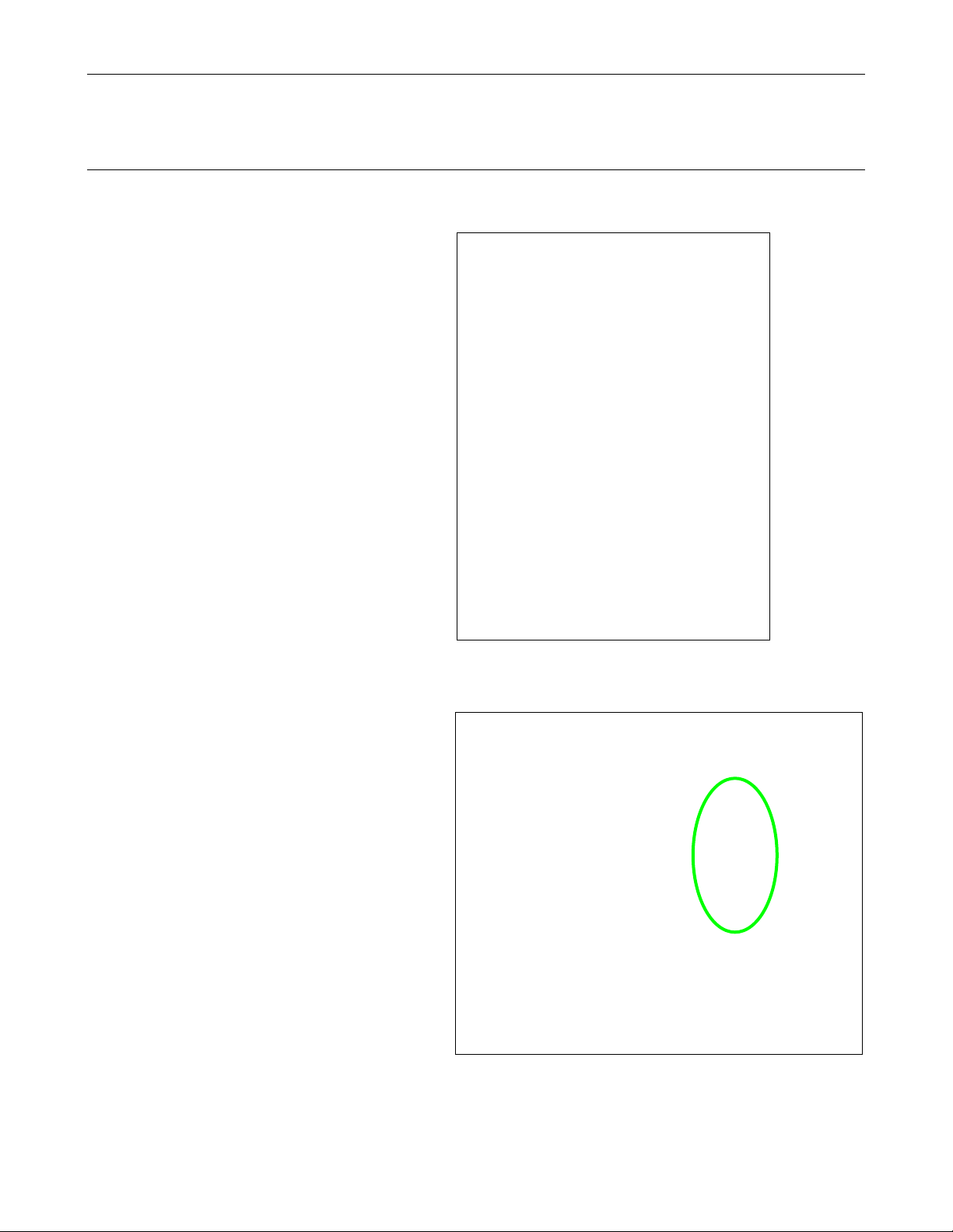
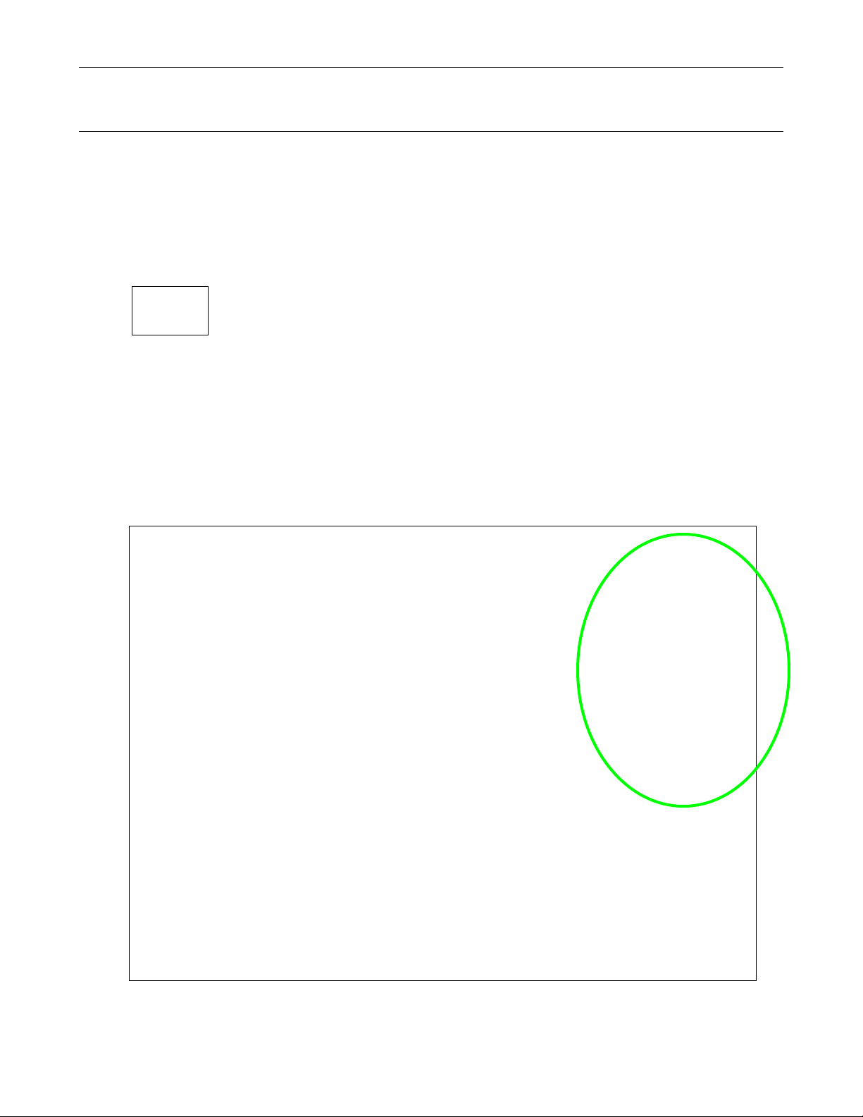
Ensure that the Camera Control module is active. See the image of the screen below noted by the green circle.
The text must be black as shown. If the Camera Control is inactive (with grey text) proceed to the troubleshooting
section: Inactive Camera Window.
Select the Petri dish plate diameter from the Camera Control module. The choices are 6cm, 10cm, and 15cm.
Select the smallest colony size for this plate. The choices are <1mm and 1mm+. If <1mm is selected the
smallest colony size is below 1mm. The count will be faster if 1mm+ is chosen.
Choose the White Light option from Colony Lighting. The Dim to Bright slider will be disabled unless using the
Fluorescent Colony Lighting option. If counting fluorescent colonies go to the Fluorescent Colony Counting
section of the manual.
Counting Colonies
Quick Capture
Place the Petri dish to be counted on the transillumination surface.
Select the appropriate lighting option for the sample. If unsure, turn the selector switch (located on the front of the
colony counter) to Base Lighting > Trans and remove the black plate (if present). The Trans lighting option will
apply to most applications.
If the colony counter is not already open, double click onto the Doc-It Colony Counter icon on the desktop.
Page 14

ColonyDoc-It Imaging Station 14
Insert the Petri dish inside the colony counter.
Click the Preview button in the Camera Control module
and move the Petri dish until it is centered inside the red
circle. The outer red circle should fall just inside the Petri
dish outer edge. If it does not, make sure that the correct
Plate Diameter size was selected.
There are two focusing methods provided for imaging.
The first is Auto focus. Auto focusing allows the camera
to automatically find the appropriate focus for the sample.
Manual focus is provided should the camera need
intervention from the user to more clearly picture the
image.
Manual focus buttons allow users to adjust the focus in
small increments or large increments .
Brightness adjusts the brightness of the image.
Click the Capture button from the Camera Control
module to take a picture.
Click Start Colony Count in the Colony Count module at
the left of the screen to start the counting process.
Select Automated Count or Manual Count. Go to the
Automatic Count section in the manual to complete steps
for automated count. Go to the Manual Count section in
the manual to complete steps for the manual count.
NOTE: The User Defined Template Count is grayed out initially because there are no templates created.
Template counting allows users to create counting templates for frequently counted Petri dish plates. The manual
count process must be performed before template settings can be established.
TIP: The ColonyDoc-It doors can be easily removed if fluorescent colonies will not be counted. Go to the Removing
ColonyDoc-It Doors section in this manual for instructions.
Page 15

ColonyDoc-It Imaging Station 15
Lighting Tips:
There are four options for lighting the Petri dish. Epi Lighting options include White light and Blue light and
these sources light the Petri dish from the top. Base Lighting options include Trans and Darkfield and
these sources light the Petri dish from the bottom
Blue light is used to excite GFP stained colonies.
A majority of samples prepared using the spread method and a transparent substrate that are bacterial,
yeast, or mold are best viewed using Base Lighting > Trans.
If there is excessive handwriting on the bottom of the Petri dish, membrane paper, or stickers, then use Epi
Lighting > White or Base Lighting > Darkfield.
Use Base Lighting > Darkfield when counting a pour plate.
Using the black plate on top of the transillumination surface in combination with Epi Lighting sources
provides contrast that improves colony counting results.
Preparing Samples:
When preparing samples, write on the bottom edge away from the center of the Petri dish to increase
counting accuracy.
Before proceeding through the automatic counting steps, ensure that an image of the Petri dish has been captured
and is ready for analysis. See instructions on Quick Capture in this manual for more information on how to capture
an image.
Select Start Colony Count along the
left side of the screen. A new Colony
Count Type Selection window
appears. Select Automated Count
and OK.
Automatic Counting
Page 16

ColonyDoc-It Imaging Station 16
The automated count will be
displayed on the left hand side of the
screen.
Colonies can be filled in with red (as
depicted here) or outlined. Colonies
can also be numbered or annotated
using multiple colors. Go to the
Preferences section of this manual for
more details concerning changing the
appearance of the image.
If desired, colonies can be added,
deleted, split, or merged. Refer to the
respective sections of this manual for
instructions on using these tools.
Before proceeding through the manual counting steps, ensure that an image of the Petri dish has been captured
and is ready for analysis. See instructions on Quick Capture in this manual for more information on how to capture
an image.
Select Start Colony Count along
the left side of the screen. A new
Colony Count Type Selection
window appears.
Select Manual Count and OK.
The Manual Count Colony Wizard
will open.
Manual Counting
Page 17

ColonyDoc-It Imaging Station 17
The window that appears after choosing
Manual Count is the Manual Count
Colony Wizard. It contains two tabs.
The first tab is Step 1 of 2: Select Classes,
the second tab is Step 2 of 2: Finish.
The first tab allows the user to define the
region of interest inside the Petri dish to be
analyzed. The region of interest is
identified by a green circle that should
include all the colonies of interest in the
Petri dish. The software automatically
defines the region of interest but by clicking
the Define Counting Region button the
user can increase or decrease the circle
size as needed.
If a smaller or larger region of interest is
desired, click onto the Define Counting
Region button and hold and drag the
pointer over one of the corners of the circle
to change the size. Or click inside the green
circle to move the entire region of interest.
Step 1: Select Classes
Page 18

ColonyDoc-It Imaging Station 18
Sometimes applying Background
Correction to an image improves the
count.
To apply background correction click onto
the Background Correction button.
The image to the left depicts the resulting
flattened image.
The Select Classes tab allows users to
select the number of classes and colonies
in the Petri dish sample.
To count the desired colonies, ensure that
the Add Points button is highlighted in
yellow and click on a colony to be
counted in the original image of the Petri
dish. (A smaller duplicate image of the
original is present in the Step 1 of 2:
Select classes tab, but a colony cannot
be selected from this image.)
Classes are defined as different types of
bacteria, yeast, or mold present on the
sample. The software can detect various
types of classes in one dish. To add a
class, click onto the Add button in the
Classes section of the window.
Click on a colony
Page 19

ColonyDoc-It Imaging Station 19
Once the first colony is selected, the new
image in the Step 1 of 2: Select classes
window will show a black background
along with all of the colonies that contain
the same color as the point identified in
the Analysis Details window.
Adjust the Point Sensitivity slider to
increase or decrease sensitivity.
Increasing and decreasing sensitivity
almost always improves the final count.
Continue clicking on colonies in the
captured image to add points and adjust
the Point Sensitivity as necessary until
the black and white image shows all the
colonies of interest identified in white.
To remove points or classes from the
Analysis Details window, highlight the
point and select Remove Point or
highlight the class and select Remove.
Click the Count button to proceed to the
next tab.
NOTE: The Step 1 of 2: Select classes tab allows the settings created in this window to be saved in a user defined
template. If there are no templates created, the drop down menu will list Default as the only template option. Go to the
Templates section of this manual for instructions on creating templates.
The software will automatically move to the
second tab Step 2 of 2: Finish after Count
is selected in Step 1 of 2: Select classes.
To filter the colonies, adjust the shape or
colony size in the Filter colonies section.
Change slider buttons for shape (from
circular to irregular) and size (1 pixel to 200
pixels) to capture additional colonies or
eliminate colonies.
This window is a second means to save
settings into templates. Go to the
Templates section of this manual for
instructions on creating templates.
Click Finish to exit the manual count mode
and to get the final count.
Step 2: Finish
Page 20

ColonyDoc-It Imaging Station 20
To save a template in Step 1 of 2: Select
classes, add the desired points and classes if not
already selected) and click the New button in the
Template section of the window.
If additional information is needed, refer to the
Manual Count instructions in this manual.
A New Template pop-up window will ask for a
new Template name.
Type in the new name and select OK.
The Template name window will close and direct
back to the Step 1 of 2: Select classes tab.
Click on the Count button to proceed to the Step
2 of 2: Finish tab.
Creating Templates
Templates allow the user to set colony counting parameters so that plates with similar properties are counted
quickly and consistently.
To set a template for any Petri dish, choose Start Colony Count (or Restart Colony Count if the Petri dish has
been counted before) in the Colony Count module, then select the Manual Count function. A template can be
saved during operation Step 1 of 2: Select classes or Step 2 of 2: Finish.
Page 21

ColonyDoc-It Imaging Station 21
If the shape and size sliders are changed to
capture additional colonies, click Create template
in the Templates section of the window to save
the new settings.
Select Finish to complete the count and save the
template.
NOTE: Templates may also be saved directly in
Step 2 of 2: Finish. Users may bypass the
template creation option in Step 1 of 2: Select
classes and go directly to Step 2 of 2: Finish to
create a template.
NOTE: If a template has been saved previously, the software will pull it in automatically to be used in
any Manual Counting process.
Select Start Colony Count, and then select User
Defined Template Counting, and use the
dropdown menu to select the desired template.
Click OK.
User Defined Template Counting
Before proceeding through the next steps, a template must have been saved during the manual count process. If
there are no templates, go to the Creating Templates section of the manual to create a template.
Page 22

ColonyDoc-It Imaging Station 22
The new window will display the Total colonies
counted.
Ensure that the doors are attached to the
ColonyDoc-It or turn off the surrounding lights.
Turn the Epi Lighting switch on the ColonyDoc-It
to Blue.
Insert the Green Fluorescent Protein (GFP)
emission filter into either tray (refer to the
Installing the Filter section of this manual for
instructions) and ensure that the filter is positioned
below the camera. (If the GFP filter is in filter
position one, the filter slider should be moved all
the way to the right position.)
Insert the fluorescently stained sample into the
ColonyDoc-It.
Select the appropriate Plate Diameter, the
Smallest Colony information and choose the
Fluorescent lighting function of Colony Lighting
in the Doc-It Colony Counter software.
The slider bar may be adjusted from Dim to
Bright to provide optimum results.
Select Preview to position the plate inside the red
circle guides and then select Capture when the
image is positioned properly.
Fluorescent Colony Counting
Page 23

ColonyDoc-It Imaging Station 23
Finally, choose to count the colonies
automatically, manually, or with a template.
Refer to the Automatic Count, Manual Count, or
Template Count instructions in this manual for
additional information.
Page 24

ColonyDoc-It Imaging Station 24
Before proceeding through the zone analysis process, ensure that an image of the Petri dish has been captured
and is ready for analysis. See instructions on Quick Capture in this manual for more information on how to
capture an image.
To obtain zone analysis information for a
plate, click on the checkbox for Zone
then select Start Colony Count.
Choose to count with the Manual or User
Defined method.
Click OK.
If using the software for the first time, no
templates are created and the User
Defined Template Count option
appears grey. To create a template, first
proceed through the Manual Count
functions to store settings.
First click
on Zone
Second click on
Start Colony Count
Zone Analysis
Zone analysis provides users with zone sizing information useful for applications such as inhibition zone analysis.
Page 25

ColonyDoc-It Imaging Station 25
The window that appears after choosing
Manual Count is the Manual Count
Colony Wizard. It contains two tabs.
The first tab is Step 1 of 2: Select classes,
the second tab is Step 2 of 2: Finish.
The first tab allows the user to define the
region of interest inside the Petri dish to be
analyzed. The region of interest is
identified by a green circle that should
include all the zones of interest in the Petri
dish. The software automatically defines
the region of interest but by clicking the
Define Counting Region button the user
can increase or decrease the circle size as
needed.
If a smaller or larger region of interest is
desired, click onto the Define Counting
Region button and hold and drag the
pointer over one of the corners of the circle
to change the size.
Step 1: Select classes
Page 26

ColonyDoc-It Imaging Station 26
The Select Classes tab allows
users to select the number of
classes and zones in the Petri dish
sample.
To analyze the desired zones,
ensure that the Add Points button
is highlighted in yellow and click
on a zone to be counted in the
original image of the Petri dish.
(A smaller duplicate image of the
original is present in the Step 1 of
2: Select classes tab, but a zone
cannot be selected from this
image)
Classes are defined as different
types of bacteria, yeast, or mold
present on the sample. The
software can detect various types
of classes in one dish. To add a
class, click onto the Add button in
the Classes section of the window.
Once the first zone is selected, the
new image in the Step 1 of 2:
Select classes window will show
a black background along with all
of the zones that contain the same
color as the point identified in the
Analysis Details window.
Continue clicking on zones to add
points as necessary until the black
and white image shows all the
zones of interest identified in
white.
To remove points or classes from
the Analysis Details window,
highlight the point and select
Remove Point or highlight the
class and select Remove.
The Step 1 of 2: Select classes
tab allows the settings created in
this window to be saved in a user
defined template. If there are no
templates created, the drop down
menu will list Default as the only
template option. Go to the
Templates section of this manual
for instructions on creating
templates.
Click the Count button to proceed
to the next step.
Click on a zone
Page 27

ColonyDoc-It Imaging Station 27
The software will automatically
move to the second tab Step 2 of
2: Finish after Count is selected
in Step 1 of 2: Select classes.
To add or subtract zones, change
the slider buttons for shape
(circular to irregular) and size (1
pixel to 200 pixels) until all the
zones of interest are highlighted.
This window is a second means to
save settings into templates. Go
to the Templates section of this
manual for instructions on creating
templates.
Click Finish to exit the manual
count mode and view the results
table.
The software will redirect to the
initial screen and display the total
number of zones identified.
To view the analysis data for the
zones click onto Show Results
Window from the Main Tools
section of the Colony Count
module. A window appears that
provides information relating to the
classes, zones (listed as colonies),
statistics, and distribution of the
zones. In the report, users may
view the area and perimeter of the
zone.
To learn more about reporting
capabilities, go to the Reporting
Functions section of this manual.
Step 2: Finish
Page 28

ColonyDoc-It Imaging Station 28
To enable easier statistical reporting of
each colony or zone, the values assigned
to each colony or zone may be
renumbered.
To renumber the values assigned to each
colony or zone click Recompute Colony
Labels under the Grid Analysis Tools.
NOTE: The plate must have already been
counted.
The Recompute Colony Labels function
will read the plate from left to right and
from top to bottom. So the colony (or
zone) labeled 1 will be seated at the left
and towards the top of the plate.
Before applying “Recompute Colony
Labels” function
After applying “Recompute Colony Labels”
function
Renumbering Colony/Zone Values
Page 29

ColonyDoc-It Imaging Station 29
To perform a spiral plate count
click onto the Spiral checkbox
and then select Start Colony
Count.
Next, select from the Automated
Count, Manual Count or User
Defined Template Count.
NOTE: If using the software for
the first time, no templates are
created and the User Defined
Template Count option appears
grey. To create a template, first
proceed through the Manual
Count functions to store settings.
Additional instruction on
performing an Automated Count,
Manual Count, or Template
Count is listed in detail in this
manual.
After performing a count, a
Spiral Plate Analysis window
will appear along with a green
grid over the counted image.
To change the overlay grid size,
move the Overlay Size slider bar
to the left (to decrease the grid
size) or to the right (to increase
the grid size).
To calculate the SPLC/mL, type
in or use the up or down arrows
in the Total volume deposited
box provided. The calculated
amount will appear immediately
below the Calculate SPLC/mL
button.
First click
onto Spiral
Second click onto
Start Colony Count
Spiral Plate Counting
Page 30

ColonyDoc-It Imaging Station 30
To view the resulting Data Table
analysis for the spiral plate
count, click onto the + sign
(expanded report shown here
after clicking the + sign). The
values listed will provide the
number of colonies found in each
quadrant and section of the
counted plate.
To save the spiral plate settings
in a template, click onto Save As
and provide a name for the
template.
To print or export the data into
Excel, click onto the Print or
Export to Excel button.
While in the Spiral Plate
Analysis window, the user may
choose to move the green
overlay grid by using the Align
Spiral Plate Overlay.
To move the grid, click onto
Align Spiral Plate Overlay, click
and drag the green grid until the
center of the grid is aligned with
the center of the captured image.
To clear the spiral plate analysis,
click onto the Clear Spiral Plate
Analysis. This action will
remove the data entered for this
plate and remove the spiral plate
grid.
Spiral plate analysis may be
performed on any counted plate.
To perform the spiral plate
analysis any previously counted
plate, select the Spiral Plate
Analysis option directly above
the Align Spiral Plate Overlay
option.
Page 31

ColonyDoc-It Imaging Station 31
Users may add colonies by performing the initial count (Automated Count, Manual Count, or User Defined
Template Count), and adding colonies manually.
To add colonies, ensure that
the Add Colonies tab in the
Colony Count module is
highlighted in yellow.
If the colony is hard to see,
zoom in on the colony. In the
Zoom/Pan module, move the
slider button towards the +
sign on the right to zoom in.
A rectangular object will
appear in the Zoom/Pan
module. Move it over the
area of interest. The central
Petri dish image will appear
larger in the area identified by
the rectangular object.
Click on a colony to add.
The colony selected will now
have a circle (filled in or
outlined) around the point
selected.
The Total colonies count will
change to include the
colonies added.
Added Colony
Editing Colonies
Add Colonies
Page 32

ColonyDoc-It Imaging Station 32
To use a larger circle to
highlight the colony, go to the
Analysis Display Settings.
A new window will open.
Browse to Main Settings >
Analysis > Colony Count.
In the Add Tool section of
the window, use the drop
down menu to select between
a Circle Radius of 5, 10, 15,
or 20.
Users may delete colonies after performing the initial count (Automated Count, Manual Count, or User Defined
Template Count), and deleting colonies manually.
To delete colonies from the
Total Colonies count, ensure
that the Delete Colonies tab is
highlighted in yellow.
If the colony is hard to see,
zoom in on the colony. In the
Zoom/Pan module, move the
slider button towards the + sign
on the right to zoom in. A
rectangular object will appear in
the Zoom/Pan module. Move it
over the area of interest. The
central Petri dish image will
appear larger in the area
identified by the rectangular
object.
Click on a colony to delete.
Delete Colonies
Page 33

ColonyDoc-It Imaging Station 33
The colony circle (filled in or
outlined) will now disappear.
The Total colonies count will
change to remove the colonies
deleted.
Users may split colonies by performing the initial count (Automated Count, Manual Count, or User Defined
Template Count), and splitting colonies manually. Colonies should be split when two or more colonies are very
close together and are counted as one colony by the software.
To split colonies, ensure that
the Manual Split Colonies tab
is highlighted in yellow.
A new window will ask the user
to “Draw lines through the
colonies you want to split then
release.”
If the colony is hard to see,
zoom in on the colony. In the
Zoom/Pan module, move the
slider button towards the +
sign on the right to zoom in. A
rectangular object will appear
in the Zoom/Pan module.
Move it over the area of
interest. The central Petri dish
image will appear larger in the
area identified by the
rectangular object.
Deleted Colony
Manual Split Colonies
Page 34

ColonyDoc-It Imaging Station 34
Draw lines through two or
more colonies that are close
together and treated as one.
Use the pointer and, while
holding the left mouse button
down, move from one edge of
the colony to the other.
The Total colonies count will
change to add new colonies
identified by the split.
Users may split colonies by performing the initial count (Automated Count, Manual Count, or User Defined
Template Count), and splitting colonies by clicking on the colony to split. Colonies should be split when two or
more colonies are very close together and are counted as one colony by the software.
To split colonies, ensure that the Auto Split Colonies tab is highlighted in yellow.
If the colony is hard to see, zoom in on the colony. In the Zoom/Pan module, move the slider button towards the +
sign on the right to zoom in. A rectangular object will appear in the Zoom/Pan module. Move it over the area of
interest. The central Petri dish image will appear larger in the area identified by the rectangular object.
Click onto the colony to split.
If the colonies are hard to see, zoom in on the colonies. Refer to the Zoom/Pan section of this manual.
The Total colonies count will change to add new colonies identified by the split.
Split Colonies
Auto Split Colonies
Page 35

ColonyDoc-It Imaging Station 35
Users may merge colonies by performing the initial count (Automated Count, Manual Count, or User Defined
Template Count), and merging colonies manually. Colonies should be merged when one colony is treated as
two separate colonies by the software. Colonies will only be merged if they are less than 4 pixels apart.
To merge colonies, ensure
that the Merge Colonies tab
is highlighted in yellow.
A new window will ask the
user to “Select the desired
colonies and then press
Merge button to join them.”
If the colony is hard to see,
zoom in on the colony. In the
Zoom/Pan module, move the
slider button towards the +
sign on the right to zoom in.
A rectangular object will
appear in the Zoom/Pan
module. Move it over the
area of interest. The central
Petri dish image will appear
larger in the area identified by
the rectangular object.
Click onto the colonies to be
merged.
The Total colonies count will
now reflect changes due to
merging the colonies.
Merged Colony
Merging Colonies
Page 36

ColonyDoc-It Imaging Station 36
To set new filter parameters, click onto
the Show Results Window > Filter >
Filter class and drag the pointer to the
filter class to change.
A new Filter Colonies window will
appear with the following parameters:
Area, Perimeter, Avg Diameter, and
Circularity.
The predefined ranges are defined.
Each parameter can be changed to
accommodate a wide variety of sample
types.
The new range can either be inclusive or exclusive. Click onto the Keep Range or Exclude range depending on
sample requirements.
Enter the values to keep or exclude. Click OK.
The software will recount the colonies based on the new filter values.
Using the Software
Changing Filter Settings
To reduce user initial set-up time, filters were created to count “true” colonies and remove inherent defects from the
sample plate that would (without the filters) be included in the total colony count. The filters may prevent a colony
from being counted based on some critical parameters.
Page 37

ColonyDoc-It Imaging Station 37
To change the Label Type, from the
Analysis > Colony Count
preferences window, click the drop
down arrow and select from:
None
Class
Number (general)
Number (in class)
To change the Colony Marking, click
the drop down arrow to select from:
None
Outline
Fill
To change the Label Color, click Auto
or click the drop down arrow and
select from the colors listed.
Preferences
Open the Preferences window from File > Preferences. This window allows users to set new defaults for the
display options, label color, annotation, camera template settings and miscellaneous functions such as annotation.
Page 38

ColonyDoc-It Imaging Station 38
To change the Circle Radius, click the
drop down arrow and select from the
numbers to change circle pixel radius.
The Cameras > Canon Camera
preferences window allows users to
save modified template settings after
disconnecting. Choose from:
Ask
Always
Never
To change the Text Annotation
Behavior, select from:
Synchronize size with image
zoom which reduces/increases
the size of the annotations when
the size of image is
reduced/increased
Don’t synchronize with image
zoom which maintains the size of
the annotations if the image is
reduced or increased
Page 39

ColonyDoc-It Imaging Station 39
The Logging preferences window
allows the user to define the log file
path and the log level.
To change the Log File Path, click …
and locate a new directory.
To change the Log Level, click the
drop down arrow and select from the
list.
Toolbars
The toolbars allows users to select most commands with a single button click. The toolbars are customizable to
allow users the flexibility of including the commands used most and remove commands rarely used.
The initial default buttons include:
Open: Opens an image file previously stored
Save: Saves the current image
Save As: Saves the current image to a different name
Close: Closes the software program
Print: Prints the current image
Copy: Copies selected text, selected portions of the current image or the entire image to the clipboard
Paste: Pastes the current clipboard item onto the screen
Paste Special: Pastes an overlay of the current item in the clipboard
Cut: Cut a specific area
Edit Annotation: Select an annotation to edit
Text Annotation: Creates text annotation
Line Annotation: Creates line annotation
Rectangle Annotation: Creates rectangle annotation
Ellipse Annotation: Creates ellipse annotation
Highlighter Annotation: Creates highlight annotation
Define Image Scale: Calibrates the image to ruler dimensions instead of pixels
Page 40

ColonyDoc-It Imaging Station 40
Click the Show Results Window to bring up the colony count results.
The colony count results for the Petri dish are displayed with tabs on the upper left hand side
of the screen.
The tabs are Classes, Colonies, Statistics, and Distribution.
Number of classes in the sample
Number of colonies in that class
Percent of colonies of that colony classification in the sample
Measure Length: Allows users to draw a line and measure the distance between any two points on the
image, units depend on spatial calibration
Measure Angle: Allows users to draw an angle and measure the degree value contained in that angle
Measure Area: Allows users to draw an area and measure the area contained within that area
New ROI: Removes the active Region of Interest and prepares for a new one of the current type
Rectangular ROI: Changes the current mouse tool to select the Rectangular Region of Interest and brings
up one if already present on the current image
Elliptical ROI: Changes the current mouse tool to select the Elliptical Region of Interest and brings up one
if already present on the current image
Polygonal ROI: Changes the current mouse tool to select the Polygonal Region of Interest and brings up
one if already present on the current image
Freeform ROI: Changes the current mouse tool to select the Freeform Region of Interest and brings up
one if already present on the current image
Magic Wand ROI: Lets users select a consistently colored area (for example, a red flower) without having
to trace its outline
Reporting Functions
The results of the colony count can be displayed in the results window. To show the results:
Classes
In the Classes tab, information is displayed regarding critical parameters of each class recognized in the Petri dish.
The Classes reported category and associated values are listed below.
NOTE: All dimensional information is reported in pixels unless the plate has been calibrated.
Page 41

ColonyDoc-It Imaging Station 41
Total area of the class on the sample (in pixels)
Percentage of area of the class on the sample
Mean area of the class (in pixels)
Standard deviation of the area
Minimum area (in pixels)
Maximum area (in pixels)
Class number
Total area of that colony (pixels)
Perimeter of the colony (pixels)
Average diameter of the colony (pixels)
Circularity of the colony (numerically depicts roundness of the colony)
Colonies
In the Colonies tab, information is displayed regarding critical parameters of each colony counted in the Petri dish.
The Colonies reported category and associated values are listed below.
NOTE: All dimensional information is reported in pixels unless the plate has been calibrated.
Statistics
In the Statistics tab information is displayed which shows the Statistical property and the area (in pixels)
associated with that property.
NOTE: All dimensional information is reported in pixels unless the plate has been calibrated.
Page 42

ColonyDoc-It Imaging Station 42
Minimum area (pixels)
Colony with the minimal area
Maximum area (pixels)
Colony with the maximum area
Range of area values (pixels)
Mean of area values (pixels)
Standard deviation of values
Sum of all values (pixels)
Number of colonies
The drop down menu allows users
to report graphical information about
the average diameter, area,
perimeter, and circularity of the
colonies counted in the Petri dish.
Users may also change the number
of bins that display in the graph. (A
bin number of 50 is represented
here)
In the second window, the Property is listed alongside the Area. Several numerical values are listed which include:
Distribution
In the Distribution tab, colony area information is displayed graphically.
Exporting to Excel
To export data, from Colony count results window go to File > Send results to Excel. Save the file in Excel
format to later open the file.
The first tab shows Classes.
Page 43

ColonyDoc-It Imaging Station 43
The second tab shows Colonies.
The third tab shows Statistics.
Page 44

ColonyDoc-It Imaging Station 44
Note:
While software from UVP, LLC is an essential tool for assisting an organization to maintain CFR
compliance, UVP cannot claim that this is the only tool needed to achieve overall CFR compliance. The
organization must establish policies and procedures that work in conjunction with such efficient tools, to
ensure total compliance with 21 CFR Part 11 regulations.
Open the image in question.
Right click on the image and select
Image Information. Open the History
tab.
Events are listed in the left column.
Click on each event to view the entry
details on the right.
Add notes to each event if required.
Supporting 21 CFR Part-11 Compliance
Purpose
US - Food and Drug Administration (US-FDA) created and released Part 11 of Title 21 of Code of Federal
Regulations (CFR) in August 1997.
The rules delineate the conditions under which the US-FDA considers electronic records and electronic signatures
equivalent to paper records and paper signatures. The instructions for compliance really span the entire
organization and its practices. LS software by UVP is one piece that rightly fits into the bigger picture and supports
compliance.
Features
UVP provides software support for the following two sections of CFR regulations:
Section 11.10 (e) – For electronic records, this section requires the use of computer- generated, time-
stamped audit-trails to track changes.
The software keeps track of all changes that affect image-data. Any action in the software that modifies the
original data of an image open in the LS workspace, is logged. The log of such changes is individually
maintained for each image and is referred to as „History‟ in the software.
Section 11.3 (b) (4) – This section mandates that the system be controlled by users responsible overall for
contents of electronic records required to track.
The software provides an elaborate system of maintaining secure user accounts. Assign unique usernames and
passwords to all the users who will be using the software. Each account can also be configured to provide read or
modify access to other users‟ data. Events generated in the audit trail (above) are logged with the username.
Usage
View an Audit Trail (History)
Page 45

ColonyDoc-It Imaging Station 45
Open the image for which an Audit
Trail print copy is needed.
Go to Tools > Reports. (This option
is disabled, if no printer is available.)
A window opens with various types
of reports available.
To select to print an Audit Trail, click
the Image History item. If other
reports are required, click in the
checkbox of the other reports
needed. For example, if both an
audit trail and the image report need
to be printed, click on Image Report
and Image History.
Adjust the header and footer settings
or printer settings if necessary, and
print the trail.
Remove the four brass
thumbnuts on the filter box
and remove the filter box
from the housing.
Clean both sides of the
diopter. Remove the filter if
necessary to access the
diopter (refer to Installing
the Filter for instructions on
removing the filter.)
Print an Audit Trail (Image History)
Servicing the ColonyDoc-It
Cleaning and Care
Use 70% Isopropanol Alcohol to clean the ColonyDoc-It external surfaces, base, and doors.
Clean the ColonyDoc-It twice a day, before and after every use.
Cleaning the Diopter
Weekly clean the diopter with a soft photographic lens cleaning cloth dampened with lens cleaning solution.
CAUTION: Do not pour the solution directly onto the diopter.
The diopter is located in the filter box. To access the diopter:
Page 46

ColonyDoc-It Imaging Station 46
Once the software loads, the Camera control
window should become active. (The user
should be able to select plate diameter sizes,
colony sizes, and use all the functions within the
Camera control window.)
If the Camera control is not active, turn the
power switch off and then back on in the back of
the unit. If a window appears such as the one to
the right, select Cancel.
Replacing Switches
Follow these steps to replace the light switches on the cabinet. Refer to replacement parts for ordering information.
NOTE: This only applies to the light switches on the front of the system. Removal of other switches voids the
manufacturer‟s warranty.
Unplug the cabinet from the power source prior to removing the power switch.
To remove the switch from the unit, use a thin flathead screwdriver to pry the switch out from the housing.
Be careful not to scratch the paint of the unit in the process.
Once the switch is removed, a number of connector wires will be observed plugged onto the back of the
unit. Normally there are two black and two white wires, with some exceptions. Pull one wire out of the old
switch and put it into the same connector location on the new switch. Continue this process for each wire
until all are connect to the new switch.
Push the new switch into position.
Replacing Fuses
Fuses are located in the back of the unit.
Remove the fuse by using a flathead screwdriver to turn the fuse counter clockwise.
Pull the fuse out.
Insert the new fuse.
Use a screwdriver to turn the fuse clockwise to lock.
Ordering Replacement Parts and Accessories
Contact UVP or authorized distributor for replacement parts. For replacement parts or components not shown here,
please call UVP Customer Service or place of purchase.
Replacement Parts Part Number Qty Required
Switch, light 53-0135-01 1
Fuse, 3.15AMP/250V 5x20m, SLO BLO 56-0022-04 2
Thumbnut 62-0117-01 Order as required
GFP Filter 38-0340-01 1
Troubleshooting
Camera not active
Page 47

ColonyDoc-It Imaging Station 47
If the window is still inactive, remove the USB cable from the USB port on the computer and then plug the USB
cable back into the USB port on the computer.
If the window is still inactive, contact Technical Support.
Count not accurate
The user may add, delete, merge, and split colonies for a more accurate count.
The user may increase or decrease the count area by using the ROI tool to change the area of interest using the
Automated or Manual Count.
The user may perform a manual count. Refer to the Manual Colony Counting procedures in this manual.
The user may change the pre-defined filter settings. These settings are area of the colony, perimeter of the colony,
average diameter of the colony, and circularity of the colony. Refer to the manual section Changing Filter Settings.
Preview out of focus
If the preview image is out of focus, select Focus Preview from the Camera control module. If the camera is still
out of focus select Calibrate & Lock Focus from the Camera control module.
No power to the cabinet
Recheck main power cord connections to the system and the wall power (surge protector).
Check the power switch on the back of the unit. Make sure it is in the I position.
Check the fuse located on the main power port. Replace if necessary. If the system continues to blow fuses, call
UVP Technical Support Department.
Return Service Procedure
A Returned Goods Authorization (RGA) number must be obtained from UVP‟s Customer Service prior to
returning any product.
All returns must be authorized by UVP whether for credit, warranty replacement or repair.
Items returned for credit may be subject to a restocking charge.
Please contact our Customer Service Department for a Returned Goods Authorization (RGA).
No credit will be issued or allowed until UVP has had sufficient time to inspect the product and determine
corrective action.
Returns must be made within 30 days of issuance of the RGA number and product must be in original
packaging with all manuals and instructions.
RGA number is non-transferable and good for one use only.
Products returned for credit or replacement must be in like-new condition. All products must be free from
Bio-Hazardous contamination with a contamination-free certificate attached. Contaminated products will be
returned collect.
Products returned for repair will be evaluated by Quality Control. Estimated cost for repair will be submitted
to customer for approval. If accepted, all evaluation costs will be credited towards entire repair. Nonrepaired products can be returned at customer‟s cost.
Freight must be prepaid on goods returned to UVP by the customer.
For complete terms and conditions, contact UVP.
Page 48

ColonyDoc-It Imaging Station 48
If in North America, South America, East Asia or
Australia:
If in Europe, Africa, the Middle East or
Western Asia:
Call (800) 452-6788 or (909) 946-3197, and ask
for Technical Support during regular business
days, between 7:00 am and 5:00 pm, PST.
Call +44(0) 1223-420022, and ask for
Customer Service during regular business
days between 9:00 am and 5:30 pm.
E-mail your message to: info@uvp.com or
techsupport@uvp.com
E-mail your message to: uvp@uvp.co.uk
Fax Technical Support at (909) 946-3597
Fax Customer Service at
+44(0) 1223-420561
Write to: UVP, LLC 2066 W. 11th Street,
Upland, CA 91786 USA
Write to: Ultra-Violet Products Ltd. Unit 1,
Trinity Hall Farm Estate, Nuffield Road,
Cambridge CB4 1TG UK
Technical Support
UVP offers expert technical support on all of our products. If there are any questions about the product‟s use,
operation or repair, please contact our offices at the locations below.
Warranty
UVP, LLC warrants all of its products (except tubes, grids and filters which is 90 days) to be free from defects in
material and workmanship for a period of one (1) year from the date of purchase. All transilluminators carry a two
(2) year warranty. The foregoing warranty of UVP shall be of no force and effect if the buyer has modified or
damaged the product.
All warranties or merchantability and fitness for any purpose, and all other warranties, express or implied, except
those expressly set forth herein, are deemed waived and excluded.
UVP's duty under the warranty is limited to replacement and/or repair of the defective part at the option of UVP,
FOB, Upland, California. UVP shall not be liable for any expenses or damages incurred by purchaser except as
expressly set forth herein, and in no event shall UVP be liable for any special, incidental or consequential damages
of any kind.
 Loading...