

Page 1
Ultra-Violet Products Ltd.
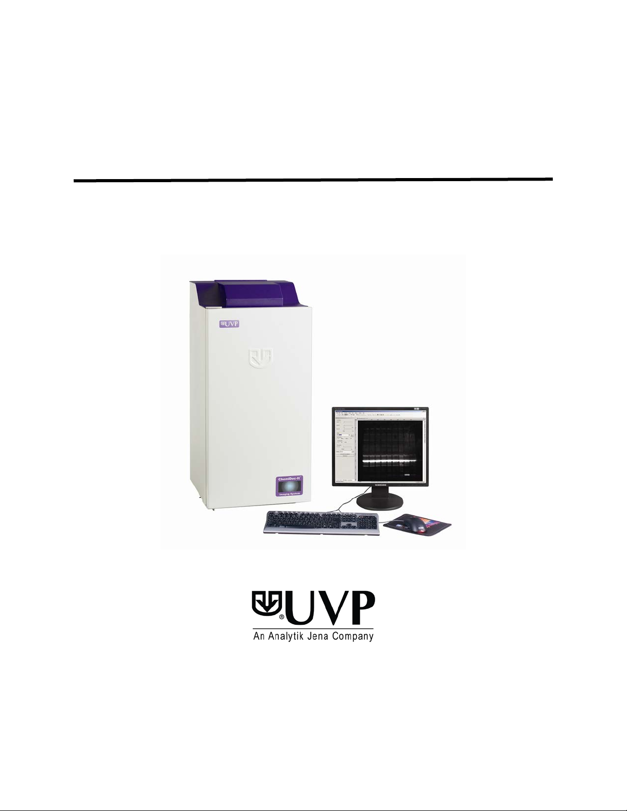
ChemiDoc-It® Imaging System
Instruction Guide
______________________________________________________________________________
UVP, LLC
2066 W. 11th Street, Upland, CA 91786
Tel: (909) 946-3197 / (800) 452-6788
Fax: (909) 946-3597
Web Site: www.uvp.com
Tel: +44(0)1223-420022 Fax: +44(0)1223-420561
Nuffield Road, Cambridge CB4 1TG UK
Unit 1, Trinity Hall Farm Estate
81-0225-01 Rev J
Page 2

ChemiDoc-It Imaging System 2
Table of Contents
Table of Contents ......................................................................................................................................................... 2
Introduction .................................................................................................................................................................. 3
Components ................................................................................................................................................................. 4
Setup Instructions ........................................................................................................................................................ 5
Installing VisionWorksLS Software ............................................................................................................................ 5
Registering the Software ........................................................................................................................................... 5
Hardware Installation ................................................................................................................................................. 6
Camera Setup ........................................................................................................................................................... 7
Operation .................................................................................................................................................................... 11
Using the System .................................................................................................................................................... 11
Capturing Images and Using Templates .................................................................................................................. 12
Focusing the Lens Using VisionWorksLS Preview .................................................................................................. 12
Capturing Images .................................................................................................................................................... 12
Using Templates ..................................................................................................................................................... 13
Service Procedures .................................................................................................................................................... 14
Return Procedure .................................................................................................................................................... 14
Troubleshooting ....................................................................................................................................................... 14
Replacement Parts and Accessories ....................................................................................................................... 14
Technical Support ................................................................................................................................................... 14
Page 3
ChemiDoc-It Imaging System 3
Introduction
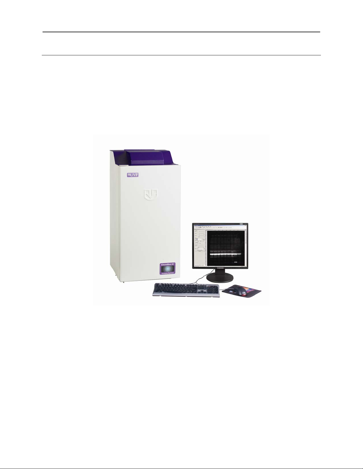
The ChemiDoc-It Imagi ng System is designed to automate chemiluminescence-based research with onetouch, pre-set or user-d efin ed PC controls for acc ur ate , repeatable imaging and analysis of
chemiluminescence and biolu mine sc ence applications. The ChemiDoc-It incorporates a light-tight darkroom
and VisionWorks
The ChemiDoc-It darkroom features built-in overhead LED white lights, wide darkroom access door,
compact footprint and a lift platform with manual adjustment.
The ChemiDoc-It includes a highly sensitive CCD camera and supplies real time live preview of images.
®
LS software to create an ideal, computer-contr ol led low light imaging environment.
ChemiDoc-It Imaging System
Page 4
ChemiDoc-It Imaging System 4
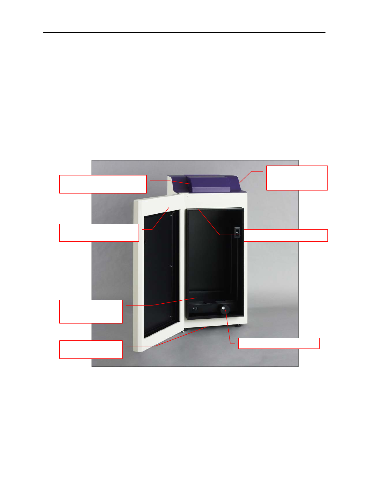
CCD camera and lens are
Epi LED white light illumination
Wide access door for easy
entry to the darkroom interior
Compact benchtop
footprint
Built-in power outlet
(optional) not shown
Lift height control knob
Main power and epi
Components
The ChemiDoc-It Imaging System is comprised of the following equipment:
Darkroom Cabinet
CCD Camera:
o MegaCam 810
o OptiChemi™ 610
o BioChemi™ 510
Lift Platform (manually adjustable)
White Epi Illumination
Chemi Tray
VisionWorksLS Software
Refer to the packing slip for a complete equipment list. System components may vary. The system may
additionally include a computer and monitor.
LED white light
housed under the camera cover
switches
for the warming plate
Minimum Computer Requirements
Processor: Pentium 4, 1.6 GHz or higher
RAM: 2GB (4GB Preferred)
Display: 1024 x 768
Operating System: Microsoft Windows XP Service Pack 2 or Newer (32-bit or 64-bit)
Internet Browser: Microsoft Internet Explorer 6.0 or later
Computer USB Ports: Computer must come equipped with a minimum of three USB ports; additional
peripherals (mouse, keyboard, printer, etc.) m ay require additional USB ports.
Page 5

ChemiDoc-It Imaging System 5
1. Double click the VisionWorksLS
Setup Instructions
Installing VisionWorksLS Software
1. Insert the VisionWorksLS flash drive into the computer.
2. Click on the Install button for VisionWorksLS.
3. Click OK, Next, agree to “I accept terms of licensing agreement”, then Next. Leave all options in
their default settings. Then click Next, Next, Install and finally Finish.
Registering the Software
Open the Software
software icon on the desktop.
2. To activate the software,
registration is required. To
immediately activate the software
online, choose On-the-Fly
activation. If the computer is not
connected to the Internet, select
Offline activation and proceed to
the following page of this manual,
or call UVP to register the
software.
3. Click Next to continue.
4. The Already have an activation
ID option is useful when reloading
the software after receiving an
initial activation code.
5. Complete all required information
on the form.
6. Fill out the Serial Number field on
the registration page. The number
is located on the installation CD.
The number should be four sets of
six numbers.
7. Once the form is completed, click
on Get Activation No. and then
click Activate once the Activation
Number appears in the box.
Page 6

ChemiDoc-It Imaging System 6
8. If the computer is not connected to
to register the software.
10. Click the link provided and
the Internet, click Offline
activation
This allows the user to obtain the
activation code and enter it at
another time.
9. Click Next to continue.
complete the form to obtain
registration instructions. Click
Finish.
Hardware Installation
Darkroom Setup
1. Remove all the tape from the darkroom.
2. Use a level to ensure that the darkroom is flat and make adjustments to the four feet of the
darkroom if necessary.
3. Plug one end of the system’s power cable into the back of the darkroom and the other end into a
wall outlet.
Page 7

ChemiDoc-It Imaging System 7
Note: Ignore this section if the system
Specifications
MegaCam 810
OptiChemi 610
BioChemi 510
Type
CCD, Monochrome
CCD, Monochrome
CCD, Monochrome
Resolution
3296 x 2472
2184 x 1472
2336 x 1752
Bit Depth
16-bit
16-bit
16-bit
Quantum Efficiency
50% peak
86% peak
50% peak
Cooling
-35˚C from Ambient
-50˚C from Ambient
-35˚C from Ambient
Binning
Yes, 1x1 thru 8x8
Yes, 1x1 thru 10x10
Yes, 1x1 thru 8x8
PC Interface
USB
USB
USB
UVP Lens Controller
Power Cable
Control Box
Power Supply
USB cable
Motorized Lens Controller Setup
The camera, lens and lens controller are all connected at the factory and come shipped as a single unit.
was shipped with a manual lens. Check
the packaging slip for additional
information about product configuration.
The lens controller is attached to the lens
at the factory. There are several cables
extending externally from the controller
and control box. Assemble the lens
controller’s connective devices as follows:
1. Ensure that the lens controller
components and connections
are assembled per the picture at
right.
2. Plug the power cable into the
power supply.
3. Plug the other end of the power
cable into an electrical outlet.
4. Wait to plug the USB cable into
the computer until the
VisionWorksLS software is
loaded.
Motorized lens controller and accompanying devices
(pictured without
camera and lens)
Camera Setup
High sensitivity, scientifi c-grade CCD cameras are designed for use with the ChemiDoc-It Imaging System.
This section covers the components and steps required to install and operate ChemiDoc-It cameras. The
following cameras are covered in this manual:
MegaCam 810
OptiChemi 610
BioChemi 510
Refer to the packing list for the camera included with the system.
MegaCam 810, OptiChemi 610 and BioChemi 510 Cameras
Components
Depending upon configuration, the components for each camera kit are outlined in the following
sections:
Installation with Motorized Lens (All Cameras)
Installation with Manual Lens (BioChemi 510 and OptiChemi 610 Only)
Note: Some components may not be shipped with all systems.
Page 8

ChemiDoc-It Imaging System 8
3
4 5 6
7
1
2
Note: The MegaCam 810, OptiChemi 610 and BioChemi 510 cameras use many of the same
components and are installed in a similar manner. Therefore, the installation instructions herein will
refer to all three cameras interchangeably.
Note: When looking at the darkroom from the front, the MegaCam 810, OptiChemi 610 and BioChemi
510 cameras attach to the bracket with the Black Thumb Screw at the right of the system. The USB and
power cables will extend from the front of the camera, facing the user.
Installation with Motorized Fixed Lens
MegaCam 810 and
OptiChemi 610
Components
1. USB Cable
2. Camera
3. Base Mount (ships
attached to the
darkroom)
4. Bracket
5. Black Thumb Screw and
Brass Thumb Nuts
6. Camera Lens &
Controller
7. Lens Controller Power
Supply Cable
The photograph shows the parts required for assembly of the MegaCam 810 camera with the motorized
lens controller on the ChemiDoc-It Imaging System. The OptiChemi 610 camera will have a different
appearance but will be ins talled in the same manner.
Note: The image above shows the 50mm f/1.2 lens (6). Another lens and/or lens controller may be
shipped with the system. Not all components may appear as shown in the image.
1. Set up the darkroom hardware and unplug all components from the power outlet.
2. The base mount (3) is preassembled and attached to the ChemiDoc-It darkroom at the UVP
factory. In the case that the base and gasket are shipped separately, secure the base mount
and gasket to the darkroom with the long screws provided (not shown).
3. Attach the camera bracket (4) to the base mount with the brass thumb nuts (5).
4. If not already removed, ta ke th e lens cap off the lens.
5. Place the camera/lens assembly over the base mount with the lens tight against the round
cutout in the rubber gasket. Secure the camera to the bracket (4) with the black thumb screw
(5) on the right side of the camera with the power and USB ports facing the front of the unit.
6. Connect the camera power supply from the darkroom into the camera. Locate the power cable
extending from the top of ChemiDoc-It darkroom.
Note: If upgrading an existing system from a prev ious camera, do not use the power supply
built into the ChemiDoc-It darkroom; instead, use the external power supply supplied with the
camera kit.
7. Connect the camera’s USB cable to the camera and into an available port on the computer.
8. Open VisionWorksLS to operate the camera. Refer to the VisionWorksLS software manual on
the Support CD or use the Help Files embedded in the software for more information.
Page 9

ChemiDoc-It Imaging System 9
BioChemi 510 &
12. Camera Power
1
2 3 4 5 6 7 8 9 10
11
12
Installation with Manual Lens (BioChemi 510 and OptiChemi 610 Only)
OptiChemi 610
Components
1. USB Cable
2. Camera
3. Base Mount
and Gasket
4. Bracket
5. Black Thumb
Screw
6. Step-Up Ring
7. Manual Lens
8. Magnifier
9. Diopter
10. Brass Thumb
Nuts
11. Power Cord
The photograph shows the parts required for assembly of the OptiChemi 610 camera with manual lens
on the ChemiDoc-It Imaging System. The BioChemi 510 camera will have a different appearanc e but
will be installed in the same manner.
Note: Not all components may appear as shown in the image.
1. Set up the darkroom and unplug all components from the power outlet.
2. The base mount (3) is preassembled and attached to the ChemiDoc-It darkroom at the UVP
factory. In the case that the base and gasket are shipped separately, secure the base mount
and gasket to the darkroom with the long screws provided (not shown).
3. Attach the camera bracket (4) to the base mount with the brass thumb nuts (10).
4. If not already removed, take the lens cap off the lens. Do not unscrew the lens cap as it will
simply pull straight off.
5. The camera (2) is preassembled with the manual lens (7), step-up ring (6) and diopter (9).
Place the camera/lens assembly over the base mount with the lens tight against the round
cutout in the rubber gasket. Secure the camera to the bracket (4) with the black thumb screw
(5) on the right side of the camera with the power and USB ports facing toward the front of the
unit.
NOTE: The camera shown may appear different than the shipped camera.
6. Connect the camera power supply from the darkroom into the camera. Locate the cable
extending from the top of ChemiDoc-It da rkroom.
Note: If upgrading an existing system from a previous camera, do not use the power supply
built into the ChemiDoc-It darkroom; instead, use the external power supply supplied with the
camera kit.
7. Connect the camera’s USB cable to the camera and then into an available port on the
computer.
8. Open VisionWorksLS to operate the camera . Refer to the VisionWorksLS software manual on
the Support CD or use the Help Files embedded in the software for more information.
NOTE: The magnifier (8) shown above is no longer used with the system.
Page 10

ChemiDoc-It Imaging System 10
Software Installation
All of the software required to operate the MegaCam 810, OptiChemi 610 and BioChemi 510
cameras, as well as their respective motorized lens controllers (if equipped), is embedded within
VisionWorksLS. Therefore, once VisionWorksLS has been installed, plug in the camera and lens
controller. No additional drivers or software are required.
Thermal Printer Setup
If this order did not include a thermal printer, move on to the next section. Otherwise, to set up the
printer:
1. Plug the power cable from the printer into the power source.
2. Press the Open button to open the lid of the printer and load the paper by allowing the loose
end of the roll to come off the top of the roll.
3. After shutting the printer lid, tear off the excess paper that is visible.
4. Plug in the USB cable from the printer to the computer.
5. Load the driver CD for the printer that came shipped in the printer box.
6. To set the printer settings click “Start” at the lower left of the computer. Next, click “Printers and
Faxes”, then right-click on the appropriate printer icon and select “Printing Preferences”.
7. Choose the following settings: High Density paper, 1280X1280, Portrait mode.
8. Click on the “Option” tab and click the “Enlarge Image to Fit Paper” box. Then, click “Apply”
and “OK”.
9. Close the VisionWorksLS software suite so it will remember and apply the printer setting
changes.
Page 11

ChemiDoc-It Imaging System 11
Motorized Lens Control
NOTE: If not using a motorized lens, proceed to the
1. In the lens area, adjust the Aperture by
2. Adjust the Focus slider to control the
Adjusting the Platform Tray Height
Platform
Counter
Main Power
Epi White Light
Darkroom and Lighting Power Switches
Operation
Using the System
The master power switch is located on the upper right side of the darkroom (see picture below). Connect the
system power as described in Hardware Installation.
1. Turn on the darkroom Main Power
switch.
2. Open VisionWorksLS software .
3. The ChemiDoc-It Imaging System may be
configured with a motorized lens that is
controlled by VisionWorksLS software.
The software has default settings which
can be modified with user-defined
templates.
For additional instructions on using VisionWorksLS
software, refer to the software help files or the
software manual available at
http://uvp.com/manuals.
(High and Low)
next section, Adjusting the Platform Tray Height.
The motorized lens is controlled by VisionWorksLS
software. To adjust the lens, click on the Acquisition
Action Tab and then on the Lighting menu button.
The lens is motorized for adjusting apertur e or foc us
settings.
moving the slider to the left to let more light
into the camera or to the right to decrease
the amount of light into the lens. The f-stop
number is shown next to Aperture.
near/far focus of the lens. Sliding the control
from right to left will adjust the focus from
near to far.
The platform tray height is adjusted by turning the
platform tray height control knob clockwise or
counterclockwise. The built-in counter displays the
relative height of the tray.
Tray Height
Control
Knob
Chemi Tray
Place the flat black Chemi Tray on top of the adjustable platform tray. Place blots in the center of
the Chemi Tray.
Page 12

ChemiDoc-It Imaging System 12
Capturing Images and Using Templates
Focusing the Lens Using VisionWorksLS Preview
1. Place the sample or focus target on the surface where the sample will be imaged.
2. Turn on the darkroom Epi Whi te Light switch (see page 13 for more information).
3. Open VisionWorksLS. Start the image preview by clicking on t he Preview button on the main
VisionWorksLS screen. With the darkroom door open, move the sample around as necessary.
4. Set the aperture to the lowest setting and adjust the exposure time to see the target clearly.
5. Zoom to the desired region of interest move the platform tray up and down by rotating the Platform
Tray Height Control Knob.
6. Adjust the focus to att ai n as sharp an image as possib le.
Note: Decrease the aperture (increase the f-stop number) after focusing the lens if possible. This will
sharpen the focus and increase the depth of fiel d at the expense of some of the brightness of the
image.
Capturing Images
1. Place the sample to be imaged on the chemi plate.
2. Turn off the epi white light for a chemi sample.
3. Under the Acquisition Action Tab, adjust the capture settings in the Camera and Lighting menus.
4. Click the Capture button.
Recommended Settings for Short Exposure Times and Focusing
Increasing the binning will incr ease both sensitivity and the camera’s refresh rate, providing “real-time”
image previewing.
1. 4x4 binning is recommended for general focusing and the fastest possible frame refresh rates.
2. Decrease the preview exposure time to 15-100 ms.
3. Always focus at a lower (faster) f-number (aperture setting on the lens) than the capture
setting. Increasing the f-number will increase the “depth of field” creating a better foc us on the
target.
Recommended Settings for Longer Exposure Times and Final Image Capture
Binning is ideal for very dim images where high sensitivity is needed. Binning of at least 2x2 is
recommended for exposures over 1-2 minutes.
1. Ensure that the camera has had an adequate
amount of time to cool before taking long
exposure images. This can be verified by
referencing the “CCD Temperature” status in
the lower-left corner of VisionWorksLS.
2. Take a test image with a short exposure (less than one minute) to ensure ideal focus before
starting longer (greater than one minute) exposures.
Page 13

ChemiDoc-It Imaging System 13
Using Templates
Set Up and Save Camera Templates
NOTE: W ithout using templates, camera settings can be manually adjusted directly in the software.
Chemi Blot Pre-Capture Positioning: For this application, use a preview binning of 1x1, a capture
binning 1x1 and an exposure time of 0.2sec. Have the darkroom door cracked open to let in some
ambient light.
Chemi Blot with Fast Capture and Lower Resolution: For this application, use a preview binning
of 8x8, a capture binning of 4x4, and an exposure time of 15sec. This setting is useful for quick
screening; the time can be increased or decreased depending on the intensity of the signal from the
blot.
For better resolution, set the preview binning to 8x8, the capture binning to 2x2, and the exposure
time to 60sec. The preview is the same and the exposure time is intermediate, but the final image is
of higher resolution than when using 4x4 binning.
Chemi Blot with Slower Capture and Higher Resolution: For this application, use a preview
binning of 8x8, a capture binning of 1x1, and an exposure time of 5min. This will result in the best
possible capture resolution. However, the exposure takes longer because the image is not binned.
Set Up Darkroom Templates
NOTE: W ithout using templates, darkroom settings can be manually adjusted directly in the software.
Chemi Blots: Place a business card on the chemi tray in the ChemiDoc-It darkroom. Set the lens to
the fastest f-stop (the lowest aperture number) and focus on the business card with darkroom door
cracked open, no emission filter in place, no lighting on, and either the lens zoomed or the lift platform
positioned to fit the blot.
To Process a Blot
1. Place the Western blot on a hinged transparency or in clear plas tic bag.
2. Position the blot on the b lac k c hemi tray.
3. Pre-focus and position the blot with the lights off, the door cracked open and the lens set to the
fastest f-stop (the lowest aperture number). Use the “Chemi Blot Pre-Capture Positioning”
template discussed earlier.
4. Apply the chemi substrate on the blot (front side up) and then close the hinged transparency
over the blot and smooth out any bubbles. Reposition the blot in the field of view if needed.
Close the darkroom door.
5. Immediately start previewing with the “Chemi Blot with Fast Capture and Lower Resolution ”
template. Let the blot develop inside the darkroom while watching the prev iew. When
approaching maximum signal (which should take 2 to 3 minutes) use the “Chemi Blot with Lower
Capture and Higher Resolution” template to capture the image.
6. Light emission will drop off quickly, so capture several images as quickly as possible.
7. Save and archive orig inal files for future quantitative analysis.
8. After creating a copy of an image file, use the image invert function in VisionWorksLS, adjust the
image histogram for optimal viewing, and burn the changes to a new file.
Note: Capture and image processin g step s are descri bed in more detail in the VisionWorksLS
software manual and in the software help files.
Page 14

ChemiDoc-It Imaging System 14
Fax Customer Service at
+44(0) 1223-420561
Service Procedures
Return Procedure
A Returned Goods Authorization (RGA) number must be obtained from UVP Customer Service before
returning any product.
Troubleshooting
No Power to the Darkroom
1. Recheck main power cord connections to the darkr oom.
2. Check fuses, located at the back of the unit, near the power port. A flat-head screwdriv er will be
required. Turn the fuseh old er cap count er clo ckw ise and the fuse holder will pop out. Inspect the
thin wire within the glass fuse to see if there is a break in the wire. If so, replace the fuse(s). If fuses
are blowing repeatedly, contact UVP Technical Support for additional troubleshooting.
Replacement Parts and Accessories
Replacement parts and accessories part numbers are shown below. To order accessories or replacement
parts, contact UVP’s offi c es listed under Technical Support.
Part Description Part Num ber
Power Cord, 100V/115V 46-0023-38
Power Cord, 230V 46-0023-39
Thermal printer, digital archive quality 256-grayscale (Mitsubishi) 89-0069-06 (115V)
Thermal printer, digital archive quality 256-grayscale (Mitsubishi) 89-0069-07 (230V)
Thermal printer, digital archive quality 256-grayscale (Sony for Europe) 89-0069-15 (230V)
Thermal paper, Mitsubishi (4 rolls – 800 images) 89-0038-01
Thermal paper, Sony high gloss (5 rolls – 1000 images) 89-0174-01
Thermal paper, Sony glossy (5 rolls – 1000 images) 89-0031-01
Technical Support
UVP offers expert technical support on all of UVP’s products. If there are any questions about the product
use, operation or repair, please contact UVP’s offices at the locations below. Or go to UVP’s web site and
click the Tech Support > BioImaging Systems.
NOTE: A Returned Goods Authorization (RGA) number must be obtained from UVP’s Customer Service
prior to returning any product.
If you are in North America, South America,
East Asia or Australia:
Call (800) 452-6788 or (909) 946-3197, and ask
for Technical Support during regula r busin es s
days, between 7:00 am and 5:00 pm, PST.
E-mail your message to: info@uvp.com or
techsupport@uvp.com
Fax Technical Support at (909) 946-3597
Write to: UVP, LLC. 2066 W. 11th Street, Upland,
CA 91786 USA
ChemiDoc-It and VisionWorks are registered trademarks of UVP, LLC.
OptiChemi and BioChemi are trademarks of UVP, LLC.
If you are in Europe, Africa, the M iddle East or
Western Asia:
Call +44(0) 1223-420022, and ask for Customer
Service during regular bus iness days between 9:00
am and 5:30 pm.
E-mail your message to: uvp@uvp.co.uk
Write to: Ultra-Violet Products Ltd. Unit 1, Trinity
Hall Farm Estate, Nuffield Road, Cambridge CB4
1TG UK
 Loading...