

Page 1
GelDoc-It
2
®
& ChemiDoc-It
2
®
Installation and User Instructions
Imagers
UVP, LLC Ultra-Violet Products Ltd.
2066 W. 11th Street Unit 1, Trinity Hall Farm Estate
Upland, CA 91786 Nuffield Road, Cambridge CB4 1TG UK
Phone: (800) 452-6788 Phone: +44(0)1223-420022
Fax: (909) 946-3597 Fax: +44(0)1223-420561
Web Site: www.uvp.com
81-0220-01 Rev N
Page 2

GelDoc-It
2
and ChemiDoc-It2 Imagers 2
Table of Contents
Table of Contents ......................................................................................................................................................... 2
Introduction .................................................................................................................................................................. 3
System Components ................................................................................................................................................... 4
Minimum Computer Requirements ............................................................................................................................ 4
Cameras .................................................................................................................................................................... 5
Optional Equipment ................................................................................................................................................... 6
Setup Instructions ........................................................................................................................................................ 8
Components .............................................................................................................................................................. 8
Connecting the Power Cables ................................................................................................................................... 8
Installing the Emission Filter ...................................................................................................................................... 8
Camera Setup ........................................................................................................................................................... 9
Software Installation ................................................................................................................................................ 12
Using the System ....................................................................................................................................................... 15
Powering Up the System ......................................................................................................................................... 15
Using the Filters ...................................................................................................................................................... 15
Using the Transilluminator ....................................................................................................................................... 16
Using the Overhead (Epi) Lighting .......................................................................................................................... 16
Using the UV Gel Viewer Window ........................................................................................................................... 16
Capturing Images and Using Templates .................................................................................................................. 17
Image Focusing ....................................................................................................................................................... 17
Capturing Images .................................................................................................................................................... 17
Using Templates ..................................................................................................................................................... 18
Service Procedures .................................................................................................................................................... 20
Return Procedure .................................................................................................................................................... 20
Replacement Parts and Accessories ....................................................................................................................... 20
Troubleshooting ....................................................................................................................................................... 20
Care and Cleaning .................................................................................................................................................. 21
Technical Support ................................................................................................................................................... 21
Page 3

GelDoc-It
2
and ChemiDoc-It2 Imagers 3
Introduction
The GelDoc-It2 Imager is designed as a high resolution imager capable of capturi ng, doc u ment ing and
analyzing fluorescent gel images.
In addition to gel documentation capabilities, the ChemiDoc-It
grade CCD camera allowing users to capture, document and analyze chemiluminescent blot images,
including Western blots.
The GelDoc-It
for image acquisition and analysis function s. The darkroom has a UV-blocking gel viewer window, built-in
overhead epi white lighting, a UV transilluminator and a four-position emission filter wheel with an ethidium
bromide (EtBr) emission filter included as sta ndard .
2
Imager is equipped with a cooled, scientific-
2
and ChemiDoc-It2 Imagers incorporate a light-tight darkroom with VisionWorks®LS software
Page 4
GelDoc-It
Processor:
Pentium class, 1.6 GHz or higher
RAM:
2 GB (4 GB Preferred)
Display:
1024 x 768
Operating System:
Microsoft Windows XP Service Pack 2 or Newer (32-bit or 64-bit)
Internet Browser:
Microsoft Internet Explorer 6.0 or later
Computer USB Ports:
Computer must come equipped with a minimum of three USB
require additional USB ports.
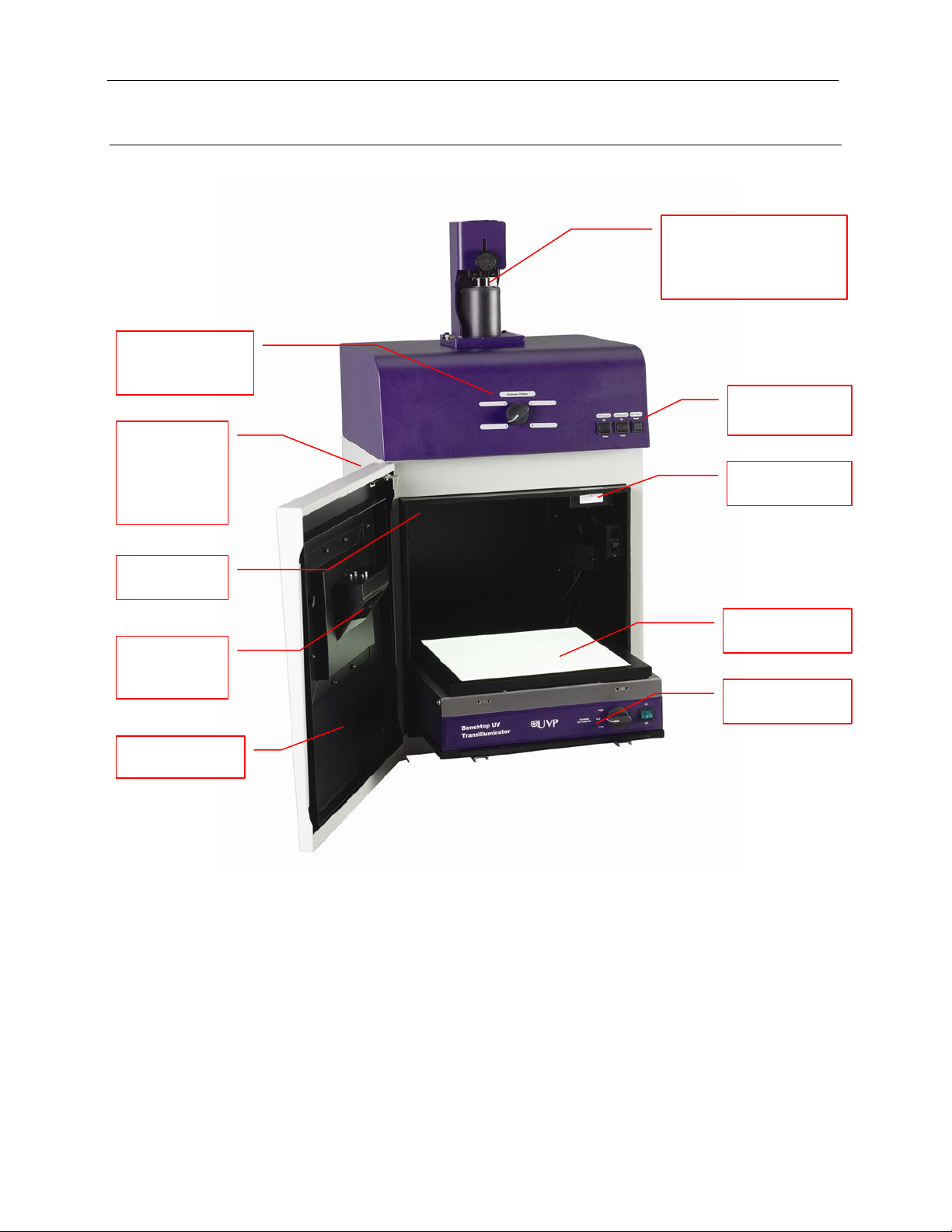
Camera and Lens Kit
Lighting and UV
Darkroom
Access Door
Epi Overhead
White Light
Four Position
UV Safety
Interlock Switch
UV-Safe Gel
Window
Roll-Out
Transilluminator
LED White Light
Plate (Optional)
Access port
2
and ChemiDoc-It2 Imagers 4
System Components
Refer to the packing slip and pictured components for parts included with the system.
Emission Filter
Selector
for optional
BioLite™
MultiSpectral
Light Source
(actual configuration may
be different than shown in
the photo)
Timer Switches
Viewer
Minimum Computer Requirements
ports; additional peripherals (mouse, keyboard, printer, etc.) may
Page 5

GelDoc-It
2
and ChemiDoc-It2 Imagers 5
Cameras
Lens Kit (Motorized or Manual)
Ethidium Bromide (EtBr) Emission Filter
Darkroom
GelDoc-It2: The GelDoc-It2 is equipped with the GelCam 310 camera, a scientific-grade monochrome
CCD camera with a resolution of 2.0MP (1600x1200) with USB 2.0 PC interface.
ChemiDoc-It
MegaCam 810 scientific-grade monochrome CCD camera. All cameras are Peltier cooled and offer full
16-bit file bit depth:
The BioChemi 510 camera has 2.1MP resolution with Peltier cooling to -35°C from ambient. The
BioChemi 510 has a peak quantum efficiency of 50% and is capable of binning from 1x1 to 8x8.
The OptiChemi 610 camera has 3.2MP (2184x1472) resolution with Peltier cooling to -50°C from
ambient. The OptiChemi 610 has a peak quantum efficiency of 86% and is capable of binning from
1x1 to 10x10.
The MegaCam 810 camera has 8.1 MP (3296x2472) resolution with Peltier cooling to -35°C from
ambient. The MegaCam 810 has a peak quantum efficiency of 50% and is also capable of binning
from 1x1 to 8x8.
All camera settings are factory pre-set for optimum performance when viewing gels, films or
membranes under low light level conditions. Contact UVP Technical Support prior to making any
adjustments to the camera settings.
2
: The ChemiDoc-It2 is equipped with the BioChemi™ 510, OptiChemi™ 610 or
The zoom lens used with the GelCam 310 and BioChemi 510 cameras comes in two configurations:
The motorized lens is controlled via VisionWorksLS Software.
The manual lens requires manual user adjustment.
Some lenses may be fitted with a close-up diopter. The diopter is used for focusing on obje cts at the
focal length of the GelDoc-It
The ethidium bromide (50mm square) UV-blocking bandpass interference filter blocks UV and IR
radiation emitted from the transilluminator. T he filter is pla ce d in the filter wheel below the camera
assembly. The filter allows visualization of fluorophores from 580-630nm, targeting the ethidium
bromide emission peak of 605nm.
Additional filters are available for other specific fluorophores. Filters can also be removed when imaging
non-fluorescent media (including chemiluminescent blots, protein gels, colony plates, etc.) in order to
produce brighter images. Contact UVP for ordering information.
The darkroom is light tight to provide optimal imaging conditions. Darkroom features include:
2
/ChemiDoc-It2 darkroom.
Overhead white light
Roll-out transilluminator tray
UV-safe gel viewer window built into the darkroom door
Side pocket for storage of materials
Four position emission filter wheel
Brackets for installing optional UV handheld lamps for epi (overhead) UV illumination
Built-in power ports for transilluminator and optional overhead UV handheld lamps
Built-in power cord for optional LED White Light Plate
UV safety interlock switch with manual override to disable UV transillumination and
optional UV epi illumination when darkroom door is opened
Page 6
GelDoc-It
UV Lamp
Fluorescent Focus Target
2
and ChemiDoc-It2 Imagers 6
Transilluminator
The GelDoc-It2 and ChemiDoc-It2 Imagers can accommodate UVP’s Benchtop and FirstLight
transilluminator models. UVP offers a variety of transilluminator configurations, including Benchtop
models with multiple wavelengths and variable intensities as well as the highly uniform, patented
FirstLight
Note: For UV protection and to extend the life of the UV transilluminator, the system incorporates a tenminute transilluminator shutoff timer. The timer shuts off the transilluminator after ten minutes of
operation. A push button on the front of the darkroom allows the user to reset the timer. Alternately, the
timer can also be reset by opening and closing the darkroom door.
®
transilluminator. Refer to the packing slip for the transilluminator included with your system.
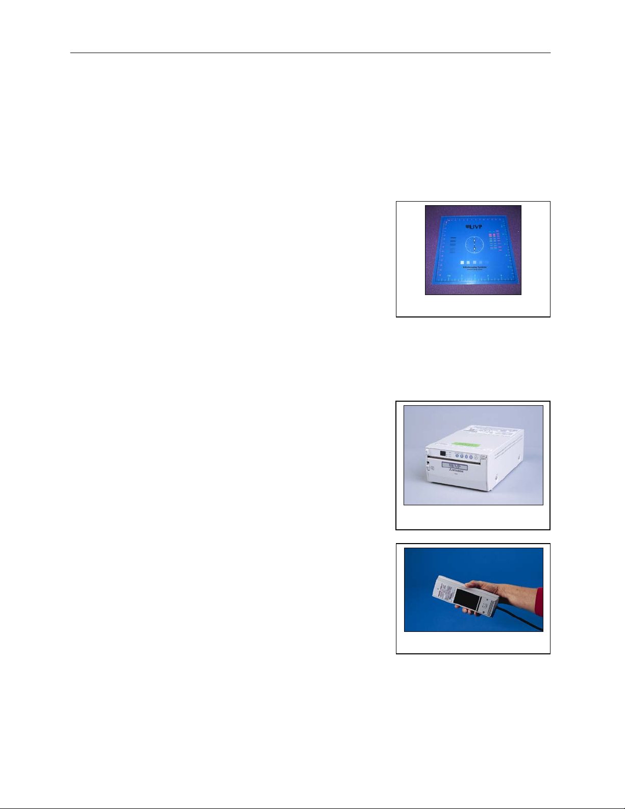
Fluorescent Focus Target
The UVP Fluorescent Focus Target fluoresces when placed
on a UV transilluminator or when exposed to overhead UV.
The Target provides sharp fluorescent images to aid in
adjusting the lens and camera settings for ideal imaging
results.
Optional Equipment
UVP offers a variety of optional equipment to support the needs of varying laboratory environments. Refer to
“Replacement Parts and Accessories” at the end of this manual for optional equipment part numbers.
Thermal Printer
The thermal printer provides archive quality, 256 grayscale
prints and five optional cost-effective print size s.
Thermal Printer
UV Handheld Lamps for Overhead Lighting
Two 4-watt ultraviolet lamps can be connected inside the
darkroom to provide epi UV illumination. These lamps can be
switched on or off using the switch on the front of the
darkroom and can also be removed from the darkroom and
used as standalone handheld lamps (as seen in the image to
the right).
Page 7

GelDoc-It
LED White Light Plate
2
and ChemiDoc-It2 Imagers 7
LED White Light Plate
The LED White Light Plate emits high uniformity with less
than 5% coefficient of variance (CV). Plug the LED White
Light Plate directly into the power supply within the system
darkroom, or store it in the exterior darkroom side pocket
when not in use.
Converter Plates
An alternate to the LED White Light Plate, the UV/White
Converter Plate allows imaging of non-fluorescent sta ined
media with an ultraviolet transilluminator. The converter plate
is specially coated to convert 302nm UV output to white light
rather than using a separate white light box or plate.
The Visi-Blue™ Converter Plate (not shown) converts UV
to a safe 460-470nm blue wavelength designed for use with
blue excitation samples and SYBR Green, SYPRO Orange
and GFP stains.
UV/White Converter Plate
Page 8

GelDoc-It
1. Carefully remove filter from the protective
2
and ChemiDoc-It2 Imagers 8
Setup Instructions
Components
When unpacking the GelDoc-It2 and ChemiDoc-It2, the following items will be included:
GelDoc-It
Transilluminator
Camera with lens and bracket
Ethidium Bromide (EtBr) emission filter
Electrical and computer cables
VisionWorksLS Software
WARNING: Do not attempt to perform any setup procedures while the system is plugged in or powered on
unless otherwise instructed.
CAUTION: Do not install the system in areas with high moisture, dust or high temperatures. Keep the
equipment away from motors or any other large magnetic equipment apparatus.
Connecting the Power Cables
2
or ChemiDoc-It2 darkroom
1. Inside the darkroom, place the transilluminator on the roll-out tray. Connect the transilluminator to
one end of the jumper cable. Connect the other end of the jumper cable to the interior of the
darkroom. Turn the UV transilluminator’s main power switch (green switch) ON.
2. If insta lling the L ED White Light Plate, place the plate on top of the UV transilluminator and connect
the power cord coming from inside the darkroom to the back of the Plate.
3. If installing epi UV handheld lamps, place the lamps in the brackets located at the top of the
darkroom. Plug the handheld lamps into the outlets provided inside the darkroom. Place the power
switches located on the outside of the handheld lamps in the ON position.
4. Connect the main power cord from the back of the darkroom to a surge-protected power outlet.
Installing the Emission Filter
To install the 50mm2 ethidium bromide (EtBr) filter:
plastic case, holding the filter at the edges to
prevent placing fingerprints on the glass
surface.
Note: It may be necessary to remove the base
and camera assembly to insert new filters
(photograph shows camera and base removed).
2. The filter wheel is located inside the top of the
darkroom. Before placing the filter in the filter
wheel, ensure that the text on the edge of the
filter is positioned so it is right side up when
facing the installer.
3. Place the filter in the filter wheel.
4. Write the name of the filter on the appropriate
label at the front of the darkroom.
Page 9

GelDoc-It
Specifications
GelCam 310
Type
CCD, Monochrome
Resolution
1600 x 1200
Bit Depth
16-bit
PC Interface
USB
The GelCam 310 camera, zoom lens and diopter
1. Remove the cap from the lens (if in place).
2. Using the four brass thumb screws provided,
3. Slide the camera and lens assembly into the
Tighten brass thumb
bracket to the base
Camera and
Black thumb
2
and ChemiDoc-It2 Imagers 9
Additional and replacement emission filters are available through UVP. Refer to the Replacement
Parts and Accessories se cti on of this manual for ordering information .
Camera Setup
High sensitivity, scientifi c-grade CCD cameras are designed for use with UVP’s GelDoc-It2 and ChemiDoc-it2
Imagers. This section covers the components and steps required to install UVP’s cameras. The following
cameras are covered in this manual (refer to the packing list for the camera included with your specific
system):
GelCam 310 (GelDoc-It
BioChemi 510 (ChemiDoc-It
OptiChemi 610 (ChemiDoc-It
MegaCam 810 (ChemiDoc-It
GelCam 310 Camera
2
)
2
)
2
)
2
)
GelCam 310 Camera with Manual Lens
are assembled at the UVP factory. (Note:
Camera may be a different size or color than
shown)
secure the bracket to the base on the
darkroom.
camera bracket. Slide the lens through the
center hole in the black rubber gasket. The
gasket forms a seal around the lens.
4. Insert and tighten the black thumb screw in
the central hole of the camera to secure the
camera to the bracket.
5. Plug the camera cable into the top of the
camera but do not plug the other end of the
USB cable into the computer until
VisionWorksLS software has been installed.
manual lens
assembly
screw
screws to secure the
Page 10

GelDoc-It
The GelCam 310 camera, zoo m lens and diopter
1. Remove the cap from the lens (if in place).
2. Using the four brass thumb screws provided,
3. Slide the camera and lens assembly into the
6. Mount the lens control box on the hook
Tighten brass
to the base
Camera cable
Power switch for the Lens
Control Box
Central hole
Black thumb
2
and ChemiDoc-It2 Imagers 10
GelCam 310 Camera with Motorized Lens
are assembled at the UVP factory. (Note: Camera
may be a different size or color than shown)
secure the bracket to the base of the
darkroom.
camera bracket.
4. Insert and tighten the black thumb screw in
the central hole of the camera to secure the
camera to the bracket.
5. Plug the camera cable into the top of the
camera but do not plug in the other end of the
USB cable until VisionWorksLS software has
been installed.
screw
thumb screws to
secure the bracket
located at the back of the darkroom.
Page 11

GelDoc-It
7. Plug the serial cable from the motorized lens
8. Connect the USB cable to the PC connection
Specifications
MegaCam 810
OptiChemi 610
BioChemi 510
Type
CCD, Monochrome
CCD, Monochrome
CCD, Monochrome
Resolution
3296 x 2472
2184 x 1472
2.1MP
Bit Depth
16-bit
16-bit
16-bit
Quantum Efficiency
50% peak
86% peak
50% peak
Cooling
-35˚C from Ambient
-50˚C from Ambient
-35˚C from Ambient
Binning
Yes, 1x1 thru 8x8
Yes, 1x1 thru 10x10
Yes, 1x1 thru 8x8
PC Interface
USB
USB
USB
PC Connection on the
Power supply on the
Lens Control Box
2
and ChemiDoc-It2 Imagers 11
into the lens control box.
port on the lens control box. Leave the other
end of the USB cable unplugged until
installation of VisionWorksLS is complete.
9. Connect the power supply to the lens control
box and into the power outlet.
MegaCam 810, OptiChemi 610 and BioChemi 510 Cameras
Components
Note: Some components may not be shipped with all systems.
Note: The MegaCam 810, OptiChemi 610 and BioChemi 510 cameras use many of the same
components and are installed in a similar man ner. Therefore, the installation instructions herein will
refer to all three cameras interchangeably.
Lens Control Box
Page 12

GelDoc-It
3
4 5 6
7
1
2
2
and ChemiDoc-It2 Imagers 12
1. USB Cable
2. MegaCam 810/OptiChemi
610/BioChemi 510 Camera
3. Base Mount (ships attached
to the darkroom)
4. Bracket
5. Black Thumb Screw and
Brass Thumb Nuts
6. Camera Lens & Controller
7. Lens Controller Power
Supply Cable
Hardware Installation
The photograph shows the parts required for assembly of the MegaCam 810 and BioChemi 510 camera
kits with the motorized lens on the ChemiDoc-It2 Imager. The OptiChemi 610 camera will have a
different appearance but will be installed in the same manner.
Note: The image above shows the 50mm f/1.2 lens (6). Another lens and/or lens controller may be
shipped with the system.
1. Attach the camera bracket (4) to the base mount with the brass thumb nuts (5).
2. If not already removed, take the lens cap off the lens. Do not unscrew the lens cap, as it will simply
pull straight off.
3. Place the camera/lens assembly in the hole in the base mount. Then, use the black thumb screw
(5) to secure the camera in place, attaching it through the hole at the top of the bracket (4).
Note: When looking at the darkroom from the front, the MegaCam 810, OptiChemi 610 and BioChemi
510 cameras attach to the bracket with the Black Thumb Screw at the right of the system. The USB and
power cables will extend from the front of the camera, facing the user.
Software Installation
Installing VisionWorksLS Software
1. Insert the VisionWorksLS flash drive into the computer.
2. Click on the Install button for VisionWorksLS.
3. Click OK, Next, agree to “I accept terms of licensing agreement”, then Next. Leave all options in
their default settings. Then click Next, Next, Install and finally Finish.
Page 13

GelDoc-It
2
and ChemiDoc-It2 Imagers 13
Registering the Software
1. Double click the VisionWorksLS
software icon on the desktop.
2. To activate the software, registration
is required. To immediately activate
the software online, choose On-the-
Fly activation. If the computer is not
connected to the Internet, select
Offline activation and proceed to
the following page of this manual, or
call UVP to register the software.
3. Click Next to continue.
4. The Already have an activation ID
option is useful when reloading the
software after receiving an initial
activation code.
5. Complete all required information on
the form.
6. Fill out the Serial Number located on
the CD. The number should be four
sets of six numbers.
7. Once the form is completed, click on
Get Activation No. and then click
Activate once the Activation Number
appears in the box.
8. If the computer is not connected to
the Internet, click Offline activation
to register the software. This allows
the user to obtain the activation code
and enter it at another time.
9. Click Next to continue.
10. Click the link provided and complete
the form to obtain registration
instructions. Click Finish.
Page 14

GelDoc-It
2
and ChemiDoc-It2 Imagers 14
Installing GelCam 310 Camera Drivers
1. Open the VisionWorksLS software suite.
2. Plug the 90 degree USB cable from the camera into the USB port.
3. The computer should display Found New Hardware. Click Yes, Next, Install from a list, Next,
Don’t search, Next, double click on Show all Devices, click Have disk, and then Browse.
4. Browse to the C:\Windows\system32\drivers folder and select the STUSB.inf file.
5. Select Open and then OK to install the camera.
6. Select Finish.
Note: The installation may cause a warning message stating that the drivers are “not verified by
Microsoft”. Select Continue Anyway and the drivers will be installed correctly.
Installing MegaCam 810, OptiChemi 610 and BioChemi 510 Camera Drivers
All of the software required to operate the MegaCam 810, OptiChemi 610 and BioChemi 510 cameras,
as well as their respective lens controllers, is embedded within VisionWorksLS. Therefore, once
VisionWorksLS has been installed, plug in the camera and lens controller. No additional drivers or
software are required.
Page 15

GelDoc-It
Write the name of the
2
and ChemiDoc-It2 Imagers 15
Using the System
Powering Up the System
Once plugged in to a surge-protected wall outlet, the GelDoc-It2 and ChemiDoc-It2 systems are always
powered on. Power to specific system components, including epi and transillumination lighting, is controlled
by switches located on the front of the unit.
If using the GelDoc-It
Box (see “Camera Setup” for more infor mat ion).
The White Light and Ultraviolet power switches are three-way rocker switches. Selecting the upper switch
position will turn on the corresponding epi illumination. Selecting the lower switch position will turn on the
corresponding transillumination. Finally, selecting the middle switch position will turn off the lighting.
UV Tim er
For UV light protection and to extend the life of the UV transilluminator, there is a ten-minute
transilluminator UV Timer installed in the system. The timer shuts off the transilluminator after ten
minutes of operation. Press the button on the front of the darkroom to reset the timer.
NOTE: When the darkroom door is opened and closed again, the UV timer is automat ic ally reset.
2
system with the GelCam 310 camera, turn on the power switch for the Lens Control
Using the Filters
When installing emission filters in the GelDoc-It2 and ChemiDoc-It2, the user should note the location of the
emission filter selector knob located on the front of the system (pictured below). After installing all filters,
write the name of the filter in the white area next to the filter numbers (1-4).
To change to a different filter, turn the filter selector knob to the desired location. Ensure that the knob clicks
into place to verify that the filter is positioned correctly.
filter in the white space
next to the filter number
Page 16

GelDoc-It
2
and ChemiDoc-It2 Imagers 16
Using the Transilluminator
To use the UV transilluminator or LED White Light Plate, ensure that the components are plugged into the
system (see “Connecting the Power Cables”).
Using the power switches located on the front of the unit, select either White Light: Trans or Ultraviolet:
Trans depending upon application. When using the UV transilluminator, ensure that the green power switch
on the front of the transilluminator unit is in the ON position.
NOTE: Do not attempt to use both the White Light and Ultraviolet transillumination sources simultaneously
as system damage may occur.
NOTE: For UV light protection and to extend the life of the UV transilluminator, there is a ten-minute
transilluminator UV Timer installed in the system. See “UV Timer” for more information.
Refer to the Transilluminator manual for additional instructions on using the transilluminator.
Using the Overhead (Epi) Lighting
To operate the built-in overhead white light, use the power switch located on the front of the unit to select
White Light: Epi.
To operate the optional overhead (epi) UV illumination, ensure that the optional UV handheld lamps are
plugged into the back of the darkroom interior and are mounted to the brackets at the top of the darkroom.
Also ensure that the power switches, located on the handheld lamps, are in the ON position. Use the power
switch located on the front of the system to select Ultraviolet: Epi.
Using the UV Gel Viewer Window
The UV Gel Viewer Window, built into the darkroom door, allows users to view the interior of the darkroom
without opening the entire darkroom door.
To open the Window, press firmly on the top of the Window cover to release the pressure-sensitiv e clasp
and open the viewer. The Window glass is UV blocking while providing a clear view to the transilluminator
surface for sample viewing without opening the darkroom door.
NOTE: Close the UV Gel Viewer Window prior to capturing a light-sensit iv e image such as a
chemiluminescent blot.
Page 17

GelDoc-It
2
and ChemiDoc-It2 Imagers 17
Capturing Images and Using Templates
Image Focusing
Manual Lens (GelCam 310 with Manual Lens)
Prior to capturing an image, prepare the image focus:
1. Turn on the transilluminator and place the Fluorescent Focus Target (see “System Components”)
on the transilluminator surface. NOTE: The darkroom has a UV safety switch that turns off the
transilluminator and optional UV handheld lamps when the door is open. After closing the door,
open the UV Gel Viewer Window to ensure that the transilluminator is on and that all other lighting
is off.
2. With VisionWorksLS open, preview the image. Adjust the camera settings, including exposure time,
to enhance the image of the sample. To adjust the settings, go to the Acquisition Action Tab and
click on the Camera Menu Button. Adjust the exposure time from the Exposure Time section of the
Camera Menu.
3. Rotate the lens f-stop adjustment (top ring) so that the image is bright enough to be seen on the
screen.
4. Rotate the lens focus adjustment (bottom ring) on the lens. Adjust the focus so that the image
appears clear on the screen.
5. Rotate the zoom lens adjustment (middle ring) on the lens so that the image is ideally zoomed.
Readjust the focus ring (bottom ring) on the lens, making the image clear. Adjust the zoom so that
the object of interest is within the image preview area.
Motorized Lens (GelCam310 w/Motorized Lens, MegaCam 810, OptiChemi 610 and
BioChemi 510)
Prior to capturing an image, prepare the image focus:
1. Turn on the transilluminator and place the Fluorescent Focus Target (see “System Components”)
on the transilluminator surface. NOTE: The darkroom has a UV safety switch that turns the
transilluminator and optional UV handheld lamps off when the door is open. After closing the door,
open the UV Gel Viewer Window to ensure that the transilluminator is on and that all other lighting
is off.
2. Open VisionWorksLS software, click on the Acquisition Action Tab, and then click on the Lighting
Menu Button. Adjust the aperture, zoom (if applicable) and focus controls from the Lens Control
section of the Lighting Menu until an ideal image is seen.
3. Adjust the camera settings, including exposure time, to enhance the image of the sample. To
adjust the settings, go to the Acquisition Action Tab and click on the Camera Menu Button. Adjust
the exposure time from the Exposure Time section of the Camera Menu.
Capturing Images
1. Depending on the sample type, place the sample on the chemi tray, transilluminator or white light
plate.
2. For a chemiluminescent sample, turn off all darkroom lighting, place the black chemi tray on top of
the transilluminator and place the sample on the tray. For a fluorescent gel sample, turn on the UV
transilluminator.
3. Adjust the capture settings in VisionWorksLS.
4. Click the Capture button.
Page 18

GelDoc-It
2
and ChemiDoc-It2 Imagers 18
Recommended Settings for Short Exposures and Focusing
1. Increasing the Binning will increase the camera’s refresh rate and sensitivity. However, it also
exponentially decreases overall image resolution. Binning works by combining smaller pixels
into one larger pixel. For example, 2x2 binning will take a 2x2 area of pixels (4 pixels all
together) and combine them into one large pixel, 4x4 binning will combine a 4x4 area of pixels
(16 pixels all together) into one large pixel, and so forth, thus increasing image sensitivity but
decreasing overall image resolution.
In most cases, 4x4 preview binning is recommended for general focusing and the fastest
possible frame rates. (NOTE: Binning is not available on 300-serie s camer as )
2. Decrease the preview exposure time to 15-100ms.
3. Always focus at a lower (faster) f-number than the capture setting. Increasing the f-nu mber will
increase the “depth of field,” creating a better focus on the target.
Capturing Longer Image Exposure with the Least Noise
1. Binning can be ideal for very dim images where high sensitivity is needed. Binning of at least
2x2 is recommended for exposures over 1-2 minut es.
2. Ensure that the camera has had an adequate
amount of time to cool before taking long
exposure images. This can be verified by
referencing the “CCD Temperature” status in the
lower-left corner of VisionWorksLS.
Take a test image with a short exposure (less than 1 minute) to ensure adequate focus before
starting longer (greater than 1 minute) ex posure s.
Using Templates
Set Up and Save Camera Templates
NOTE: W ithout using templates, camera settings can be manually adjusted directly in the software.
For additional information on using templates, refer to the software Help files or the VisionWorksLS
software manual.
Chemi Blot Pre-Capture Positioning: For this application, use a preview binning of 4x4, a capture
binning 1x1 and an exposure time of 0.2sec. Have the darkroom door cracked open to let in some
ambient light.
Chemi Blot with Fast Capture and Lower Resolution: For this application, use a preview binning
of 8x8, a capture binning of 4x4, and an exposure time of 15sec. This setting is useful for quick
screening; the time can be increased or decreased depending on the intensity of the signal from the
blot.
For better resolution, set the preview binning to 8x8, the capture binning to 2x2, and the exposure
time to 60sec. The preview is the same and the exposure time is intermediate, but the final image is
of higher resolution than when using 4x4 binning.
Chemi Blot with Slower Capture and Higher Resolution: For this application, use a preview
binning of 8x8, a capture binning of 1x1, and an exposure time of 5min. This will result in the best
possible capture resolution. However, the exposure takes longer because the image is unbinned.
Set Up Darkroom Templates
NOTE: W ithout using templates, darkroom settings can be manually adjusted directly in the software.
Chemi Blots: Place a business card on the chemi tray in the darkroom. Set the lens to the fastest f-
stop (the lowest aperture number) and focus on the business card with the darkroom door cracked
open, no emission filter in place, no lighting on, and either the lens zoomed or the lift platform
positioned to fit the blot.
Page 19

GelDoc-It
To Process a Blot
2
and ChemiDoc-It2 Imagers 19
1. Place the Western blot on a hinged transparency or in clear plas tic bag.
2. Position the blot on the black c hemi tray .
3. Pre-focus and position the blot with the lights off, the door cracked open and the lens set to the
fastest f-stop (the lowest aperture number). Use the “Chemi Blot Pre-Capture Positioning”
template discussed earlier.
4. Apply the chemi substrate on the blot (front side up). Then, close the hinged transparency over
the blot and smooth out any bubbles. Reposition the blot in the field of view if needed. Close the
darkroom door.
5. Immediately start previewing with the “Chemi Blot with Fast Capture and Lower Resolution”
template. Let the blot develop inside the darkroom while watching the prev iew . When
approaching maximum signal (which should take 2 to 3 minutes) use the “Chemi Blot with Lower
Capture and Higher Resolution” template to capture the image.
6. Light emission will drop off quickly, so capture several images as quickly as possible.
7. Save and archive original files for future quantitative analysis.
8. After creating a copy of an image file, use the image invert function in VisionWorksLS, adjust the
image histogram for optimal viewing, and burn the changes to a new file.
Note: Capture and image processing steps are described in more detail in the LS software manual
and in the software help files.
Page 20

GelDoc-It
2
and ChemiDoc-It2 Imagers 20
Service Procedures
Return Procedure
A Returned Goods Authorization (RGA) number must be obtained from UVP Customer Service before
returning any product.
Replacement Parts and Accessories
To order accessories (including additional emission filters) or replacement parts for the GelDoc-It System,
contact UVP’s offices.
Part Description Part Number
UV Handheld Lamps:
UV Handheld Lamp, 254/365nm, 4 watt (115V) 95-0021-12 (2 Recommended)
UV Handheld Lamp, 254/365nm, 4 watt (230V) 95-0021-10 (2 Recommended)
Fuses:
Fuse, 3.15A (for Darkroom) 56-0022-04 (2 Required)
Fuse, 2A (for Transilluminators) 56-0002-01 (2 Required)
Fuse, 1A (for GelCam 310 Motorized Lens Controller Box) 56-0022-02 (2 Required)
Emission Filters:
Filter, Ethidium Bromide, 50mm Square 38-0220-01
Filter, SYBR Green, 50mm Square 38-0219-01
Filter, SYBR Gold, 50mm Square 38-0221-01
Transillumination Accessories:
LED White Light Plate 95-0476-01
White Light Converter Plate, 21x26cm 38-0191-01
Visi-Blue Converter Plate, 21x26cm 38-0200-01
Gel Accessories:
Gel-Cutter 85-0002-01
Gel-Ruler 85-0003-01
Gel-Scooper 85-0006-01
Gel-Tray, small 85-0007-01
Gel-Sentry DNA Preparation Plate 97-0076-01
Fluorescent Standard Step Tablet 33-0014-02
Protective Equipment:
Spectacles, UV Blocking (UVC-303) 98-0002-01
Goggles, UV Blocking (UVC-503) 98-0002-02
Faceshield, UV Blocking (UVC-803) 98-0002-04
Troubleshooting
No Power to the Darkroom or Transilluminator
1. Recheck the main power cord connection to the GelDoc-It2/ChemiDoc-It2 darkroom as well as the
power cables between the darkroom and transilluminator, LED White Light Plate or optional UV
handheld lamps.
2. Check fuses, located at the back of the unit near the power port. A flat-head screwdriv er will be
required. Turn the fuseh old er cap count er clo ckw ise and the fuse holder will pop out. Inspect the
thin wire within the glass fuse to see if there is a break in the wire. If so, replace the fuse(s). If fuses
are blowing repeatedly, contact UVP Technical Support for additional troubleshooting.
Page 21

GelDoc-It
2
and ChemiDoc-It2 Imagers 21
A Partial Image Appears on the Screen
1. Ensure that the filter wheel is not off center by turning the filter wheel selector until it fully engages
or “clicks” into place.
2. Remove the camera/lens combination and verify that the emission filter is fully seated in the filter
wheel.
Transilluminator Will Not Turn On
1. In addition to the Ultraviolet: Trans power switch on the front of the GelDoc-It2/ChemiDoc-It2
darkroom, the transilluminator itself has a power switch. Make sure that the green transilluminator
power switch, located on the front of the transilluminator, is in the ON position.
2. For UV protection and to extend the life of the UV transilluminator, there is a ten-minute
transilluminator shutoff timer installed in the system. The timer shuts off the transilluminator after
ten minutes of operation. Push the reset button on the front of the darkroom to reset the timer.
Error Messages Appear on the Screen
1. An error message that is related to the VisionWorksLS software interface or Microsoft Windows
may appear on the screen. If the message is related to Microsoft Windows, such as a reminder to
activate or update the copy of Windows, please contact your system administrator for assistance.
2. If an error message appears repeatedly and your system administrator does not recognize it as a
Microsoft Windows error, contact UVP Technical Support for further assistance.
Care and Cleaning
Use only mild soap or detergent solution for cleaning. Do NOT use oil- or petroleum-based cleaners for the
cabinet. Ensure that the system is turned OFF and unp lugg e d during cleaning.
Technical Support
UVP offers free lifetime technical support on all of its products and software. Should you have any questions
regarding the product’s use, operation or repair, contact UVP’s offices at the locations below, or visit
www.uvp.com.
If you are in North America, South
America, East Asia or Australia:
Call (800) 452-6788 or (909) 946-
3197, and ask for Customer Service
during regular business days, between
7:00 am and 5:00 pm, PST.
E-mail your message to:
info@uvp.com
Fax Customer Service, and se nd it to
(909) 946-3597
Write to: UVP, LLC 2066 W. 11th
Street, Upland, CA 91786 USA
If you are in Europe, Africa, the
Middle East of Western Asia:
Call +44(0) 1223-420022, and ask for
Customer Service during regular
business days between 9:00 am and
5:30 pm.
E-mail your message to: uvp@uvp.co.uk
Fax Customer Service, and send it to:
+44(0) 1223-420561
Write to: Ultra-Violet Products Ltd
Unit 1, Trinity Hall Farm Estate, Nuffield
Road, Cambridge CB4 1TG UK
GelDoc-It, ChemiDoc-It, VisionWorks and FirstLight are registered trademarks of UVP, LLC .
BioLite, BioChemi, OptiChemi and Visi-Blue are trademarks o f UVP, LLC.
 Loading...