

Page 1

Ultra-Violet Products Ltd.
BioSpectrum® Imaging System™
Instruction Guide
______________________________________________________________________________
UVP, LLC
2066 W. 11th Street, Upland, CA 91786
Tel: (909) 946-3197 / (800) 452-6788
Fax: (909) 946-3597
Web Site: www.uvp.com
Tel: +44(0)1223-420022 Fax: +44(0)1223-420561
Nuffield Road, Cambridge CB4 1TG UK
Unit 1, Trinity Hall Farm Estate
81-0346-01 Rev F
Page 2

BioSpectrum Imaging System 2
Table of Contents
Introduction .................................................................................................................................................................. 3
Components ................................................................................................................................................................. 4
Darkroom Cabinet ..................................................................................................................................................... 5
Five Position Filter Wheel .......................................................................................................................................... 5
CCD Camera and Lens ............................................................................................................................................. 5
UV-Safe Gel Viewer Window..................................................................................................................................... 5
Lift Platform ............................................................................................................................................................... 5
Epi Illumination .......................................................................................................................................................... 6
LED White Light Illuminator ....................................................................................................................................... 6
Chemi Tray ................................................................................................................................................................ 6
UV Transilluminator ................................................................................................................................................... 6
VisionWorks
BioLite Access Ports ................................................................................................................................................. 7
Installation .................................................................................................................................................................... 8
Installing VisionWorksLS Software ............................................................................................................................ 8
Registering the Software ........................................................................................................................................... 8
Hardware Installation ................................................................................................................................................. 9
Camera Installation .................................................................................................................................................... 13
GelCam 310 Camera .............................................................................................................................................. 13
MegaCam 810, OptiChemi 610 and BioChemi 510 Cameras ................................................................................. 15
Operation .................................................................................................................................................................... 17
Using the System .................................................................................................................................................... 17
Capturing Images ....................................................................................................................................................... 20
Focusing the Lens Using Image Preview ................................................................................................................ 20
Capturing Images .................................................................................................................................................... 20
Service Procedures .................................................................................................................................................... 21
Return Procedure .................................................................................................................................................... 21
Troubleshooting ....................................................................................................................................................... 21
Replacement Parts and Accessories ....................................................................................................................... 21
Technical Support ................................................................................................................................................... 22
®
LS Software ......................................................................................................................................... 7
Page 3

BioSpectrum Imaging System 3
Introduction
The BioSpectrum Imaging System is designed to automate research with one-touch preset or user-defined PC
controls for accurate, repeata b le imag ing and analy s is of che milu mines cen ce, fluorescence, bioluminescence and
colorimetric samples (dep ending upon configuration). The BioSpectrum incorporates a light-tight darkroo m with
VisionWorksLS software for automated control.
The darkroom has a UV-blocking window, built-in overhead 365nm UV, Visi-Blue™ 480nm and white light, UV
transilluminator, LED White Light Illuminator , chemiluminescence tray and five-position emission filter wheel with
three emission filters included. The Automated BioSpectrum includes a software-controlled lift platform, while the
Manual BioSpectrum includes a manually adjustable lift platform.
The BioSpectrum includes a highly sensitive CCD camera which supplies real-time, live preview images.
Automated and Manual BioSpectrum Imaging Systems
Page 4

BioSpectrum Imaging System 4
CCD camera and lens are
Five position filter wheel with
and SYBR Gold filters included
Epi illumination with white light,
Access ports for optional
Gel viewer
door closed
Light tight
LED White Light Illuminator
UV transilluminator
roll-out tray
Height-adjustable lift
motorized)
Chemi tray (not shown)
VisionWorksLS software
Power indicator lights
Components
The BioSpectrum Imaging System is comprised of the following equipment:
Darkroom Cabinet
Automated Filter Wheel and Emission Filters (3 Included with System)
CCD Camera and Lens:
o MegaCam 810 with either 50mm f/1.2 Fixed, 30mm f/1.4 Fixed, or f/2.8 Zoom Lens
o OptiChemi™ 610 with either 50mm f/1.2 Fixed, 30mm f/1.4 Fixed, or f/2.8 Zoom Lens
o BioChemi™ 510 with 12.5-75mm f/1.2 Zoom Lens
o GelCam 310 with 12.5-75mm f/1.2 Zoom Lens
UV-Blocking Gel Viewer Window in Darkroom Door
Automated or Manual Lift Platform (depending upon configuration)
Epi Illumination
Chemi Tray
LED White Light Illuminator
UV Transilluminator
VisionWorks
Refer to the packing slip for a complete equipment list. System components may vary. The system may
additionally include a computer and monitor, printer or BioLite™ MultiSpectral Light Source.
®
LS Software
housed under the camera cover
BioLite MultiSpectral Light
Source
window blocks
UV and allows
sample viewing
with darkroom
darkroom with
wide access
door and UV
safety switch
Ethidium Bromide, SYBR Green
480nm and 365nm UV
platform (manual or
software-controlled
controls darkroom functions,
image capture and analysis
Page 5

BioSpectrum Imaging System 5
Darkroom Cabinet
The BioSpectrum Imaging System is constructed of aluminum and is
fabricated to provide a light-tight chamber.
Darkroom Dimensions: 17.5W x 17.5D x 32H inches (445 x 445 x 813
mm)
Note: The camera cover will add additional height which will vary based
on camera application.
Five Position Filter Wheel
The filter wheel accommodates up to five emission filters. The system
comes standard with Ethidium Bromide, SYBR Green and SYBR Gold
filters. Software controls the selection of filters.
CCD Camera and Lens
The high sensitivity CCD camera and fast optics, housed in the top of
darkroom, generate high resolution images. The camera and motorized
lens are controlled by VisionWorksLS software.
Refer to the packing slip for the camera configured with your system
(Note: camera shown to the right may appear different).
Refer to the Cameras section of this manual for installation and
operation instructions for the camera shipped with your system.
UV-Safe Gel Viewer Window
The viewer in the darkroom door opens for UV-safe viewing of samples.
The acrylic window allows viewing without exposure to ultraviolet
radiation.
Lift Platform
The motorized lift platform in the Automated BioSpectrum, controlled
by the software, can be finely adjusted within a 10-inch range.
The manual lift platform in the Manual BioSpectrum can be manually
adjusted to six positions within the travel range.
Page 6

BioSpectrum Imaging System 6
Epi Illumination
The LED White Light Illuminator emits high uniformity with less than 5%
The chemi tray creates a dark background for placement of
The system may be configured with a UV transilluminator to fluoresce
Standard overhead lighting includes 365nm UV, Visi-Blue 480nm and
white light. Lighting is controlled via the software interface.
NOTE: The BioSpectrum includes an interlock switch that turns off all
UV illumination, including the epi 365nm UV, when the darkroom door is
opened. Be sure the dar kroo m door is comple tely clos ed f or pr oper UV
operation.
LED White Light Illuminator
coefficient of variance (CV). Store the White Light Illuminator in the
exterior darkroom side pocket when not in use.
Chemi Tray
bioluminescent or chemilumin esc ent samples such as Western blots,
shown here placed on top of the FirstLight
UV Transilluminator
samples. The transilluminator is positioned on a roll out tray for easy
access.
NOTE: The BioSpectrum includes an interlock switch that turns off all
UV illumination, including the transilluminator, when the darkroom door
is opened. Be sure the darkroom door is completely closed for proper
UV operation.
®
UV Illuminator.
Page 7

BioSpectrum Imaging System 7
VisionWorks®LS Software
BioLite Access Ports
VisionWorksLS software controls the darkroom functions and lighting as
well as the motorized lens and camera. The system may be configure d
with VisionWorksLS analysis software for analysis of gels, plates, blots
and other samples.
Additional optional equipment can be added to the BioSpectrum Imaging
System through the side access ports.
Side access ports allow for connecting the external BioLite
MultiSpectral Light Source for directed lighting ranging from visible
to near IR (note: the Automated BioSpectrum has two access
ports while the Manual BioSpectrum has one access port).
The access panel on the back of the darkroom provides access for
connecting additional equipment within the darkroom.
Minimum Computer Requirements
Processor: Pentium 4, 1.6 GHz or higher
RAM: 2GB (4GB Preferred)
Display: 1024 x 768
Operating System: Microsoft Windows XP Service Pack 2 or Newer (32-bit or 64-bit)
Internet Browser: Microsoft Internet Explorer 6.0 or later
Computer USB Ports: Computer must come equipped with a minimum of three USB ports; additional
peripherals (mouse, keyboard, printer, etc.) may require additional USB ports.
Page 8

BioSpectrum Imaging System 8
1. Double click the VisionWorksLS
Installation
Installing VisionWorksLS Software
1. Insert the VisionWorksLS CD (not network CD) into the computer.
2. Click on the Install button for VisionWorksLS.
3. Click OK, Next, agree to “I accept terms of licensing agreement”, then Next. Leave all options in
their default settings. Then clic k Next, Next, Install and finally Finish.
Registering the Software
Open the Software
software icon on the desktop.
2. To activate the software,
registration is required. To
immediately activate the software
online, choose On-the-Fly
activation. If the computer is not
connected to the Internet, select
Offline activation and proceed to
the following page of this manual,
or call UVP to register the
software.
3. Click Next to continue.
4. The Already have an activation
ID option is useful when reloading
the software after receiving an
initial activation code.
5. Complete all required information
on the form.
6. Fill out the Serial Number located
on the CD. The number should be
four sets of six numbers.
7. Once the form is completed, click
on Get Activation No. and then
click Activate once the Activation
Number appears in the box.
Page 9

BioSpectrum Imaging System 9
8. If the computer is not connected to
software.
10. Click the link provided and
the Internet, click Offline
activation to register the
This allows the user to obtain the
activation code and enter it at
another time.
9. Click Next to continue.
complete the form to obtain
registration instructions. Click
Finish.
Hardware Installation
Darkroom Setup
1. Remove all the tape on the darkroom (filter wheel, doors and interior cables).
2. Detach the epi light covers from the Velcro strips at the top of the darkroom and place the cov ers in
a secure location.
3. Place the UV transilluminator on the pull-out tray and connect the power jumper cable to the interior
of the darkroom and to the back of the transilluminator. See “UV Transilluminator Setup” for more
information.
4. Place the chemi tray on top of the UV transilluminator. Remove the tray when not required.
5. Unpack the LED White Light Illuminator and place it on top of the UV transilluminator. Place the
LED White Light Illuminator in the external darkroom side pocket when not in use. See “LED White
Light Illuminator Setup” for more information.
6. Use a level to ensure that the darkro om is flat. If necessary, make adjustments to the four feet of
the darkroom by rotating the system’s rubber feet clockwise or counterclockwise to raise or lower
each corner of the system.
Page 10
BioSpectrum Imaging System 10
Camera Setup
Fixed Lens Controller Setup
Lens Controller
camera and lens)
Power Cable
Control Box
Power Supply
USB cable
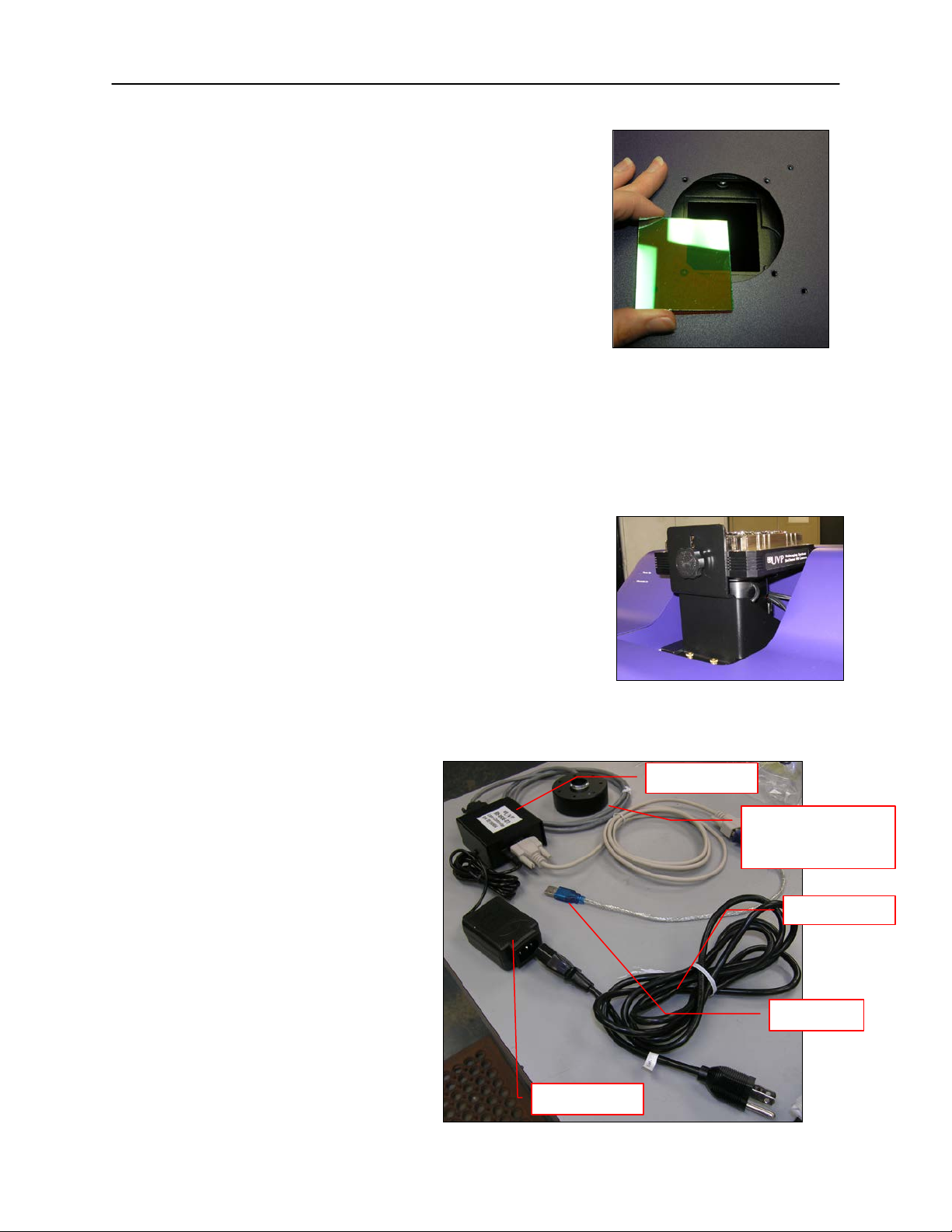
Darkroom Filter Setup
1. Ensure that the darkroom is in a fixed and permanent
location as filters may slide in movement.
2. Locate the filter wheel in the darkroom’s camera well at
the top of the darkroom, accessible when the camera and
lens are removed.
3. Using your fingers, manually rotate the filter wheel to the
appropriate filter location. Each filter location in the
darkroom is numbered for a corresponding filter. By
touching the sides of the filter only, insert the filter into the
proper location (the numbers/letters on the side of the filter
should face right side up).
Position #1 = Clear (no filter)
Position #2 = User Choice (filter provided if
ordered separately)
Placing Filter at the Top of the
Darkroom
Position #3 = SYBR Green (515-570nm)
Position #4 = SYBR Gold (485-655nm)
Position #5 = Ethidium Bromide (570-640nm)
Camera and Lens Assembly
There are several camera options. Detailed camera and bra c ket
assembly instructions for each camera are listed in the Camera
Installation section of this manual. Proceed to this section now to
continue BioSpectrum instal lation.
The fixed lens controller is attached to the
lens at the factory. There are several
cables extending externally from the
controller. Assemble the lens controller’s
connective devices as follows:
1. Ensure that the lens controller
2. Plug the power cable into the power
3. Plug the other end of the power
4. Wait unt il VisionWorksLS software
components and connections are
assembled per the picture at right.
supply.
cable into an electrical outlet.
is loaded to plug the USB cable into
the computer.
Sample Camera with Base and
Lens on Top of the Darkroom
(pictured without
Fixed lens controller and accompanying connective devices
Page 11

BioSpectrum Imaging System 11
Zoom Lens Controller Setup
UVP Lens Controller
camera and lens)
Power Cable
Control Box
Power Supply
USB Cable
Assemble the lens controller’s connective
devices as follows:
1. Ensure that the zoom lens
controller components and
connections are assembled per the
picture at right.
2. Plug the power cable into the power
supply.
3. Plug the other end of the power
cable into an electrical outlet.
4. Wait until VisionWorksLS software
is loaded to plug the USB cable into
the computer.
Zoom lens controller and accompanying connective devices
UV Transilluminator Setup
1. Plug the power jumper cord into the back of the transilluminator.
2. Place the transilluminator on the tray.
3. Plug the other end of the transilluminator power jumper cord into the darkroom outlet on the inside
top rear of the darkroom as shown below.
(pictured without
LED White Light Illuminator Setup
1. Position the LED White Light Illuminator inside the darkroom so that the FRONT label is closest to
the door.
2. Plug the power cord into the darkroom outlet labeled with “LED illumina tor pla t e” on the inside top
rear of the darkroom as shown below.
Page 12

BioSpectrum Imaging System 12
Connecting to a PC and Powering Up the System
1. Connect the USB cable from the computer to the rear exterior of the darkroom.
2. Connect the camera to the computer and darkroom per the camera instructions in the back of this
manual. Ensure that the camera is connected to its own dedicated USB port and not to a USB hub
or other similar shared device.
3. Turn the darkroom ON (power switch is located on the upper right sid e of the darkr oo m) to ensure
that the computer communicates with the darkroom.
4. Open VisionWorksLS. The software will automatically detect the new hardware.
Printer
If this order did not include a printer, move on to the next section.
To install the printer:
Setup
1. Plug the power cable from the printer into a power source.
2. Press the button to open the lid of the printer and load the paper by allowing the loose end of the
roll to come off the top of the roll.
3. Tear off the excess paper that is visible after shutting the printer lid.
4. Plug the USB cable from the printer into the computer .
5. Load the driver CD for the printer that came shipped in the printer box.
6. To set the printer settings, click “Start” at the lower left of the computer, select “Settings” and click
“Printers and Faxes”. Right click on the correct printer icon and select “Printing Preferences”.
7. Choose the following settings: High Density paper, 1280X 1280, Portrait mode.
8. Click on the “Option” tab and click the “Enlarge Image to Fit Paper” box. Then select “Apply”
and “OK”.
9. Close VisionWorksLS software to save and apply the printer changes.
Page 13

BioSpectrum Imaging System 13
Specifications
GelCam 310 Camera
Type
CCD, Monochrome
Resolution
1600 x 1200
Bit Depth
16-bit
Quantum Efficiency
NA
Cooling
None
Binning
None
PC Interface
USB
1 2 3
4 5 6
7
Camera Installation
High sensitivity, scientific grade CCD cameras are designed for use with UVP’s BioSpectrum Imaging
Systems. Th is section covers the components and steps required to install and operate UVP’s cameras .
Each camera has slightly different installation instructions, and the following cameras are covered in this
manual:
GelCam 310
BioChemi 510
OptiChemi 610
MegaCam 810
Refer to the packing list for the camera included with your specific system.
GelCam 310 Camera
Camera Specifications
Components
GelCam 310 Camera
Motorized lens
+2 diopter
Bracket
Base (typically shipped installed
on system)
Base Mounting Screws
USB Cable (for connection from
camera to PC)
NOTE: Camera may be a different
color or size than shown.
Page 14

BioSpectrum Imaging System 14
1. Slide the camera and lens assembly
4. Place the bracket on the mounting
Bracket and base securing camera
90 degree USB
cable
Serial
Insert black thumb
Black thumb screw
to bracket
Bracket
Base
Hardware Installation
into the camera base. The base comes
installed to the darkroom from the UVP
factory.
2. Plug the serial cable from the
motorized lens into the darkroom.
3. Plug the 90 degree USB cable into the
top of the camera. Leave the other end
unplugged until ready to install the
VisionWorksLS CD.
NOTE: Camera may be a different color or
size than shown.
base aligning the holes on the bracket
with the all-thread screws prot r uding
from the camera base. Using the four
brass thumb screws provided, sec ure
the bracket to the base.
5. Insert and tighten the black thumb
screw and washer to secure the
camera to the bracket. Be sure to
position the screw in the central
hole in the camera.
screw into the
central hole
for attaching camera
connection for
motorized lens
Page 15

BioSpectrum Imaging System 15
Software Installation
Install the Camera Driver
Specifications
MegaCam 810
OptiChemi 610
BioChemi 510
Type
CCD, Monochrome
CCD, Monochrome
CCD, Monochrome
Resolution
3296 x 2472
2184 x 1472
2.1MP
Bit Depth
16-bit
16-bit
16-bit
Quantum Efficiency
50% peak
86% peak
50% peak
Cooling
-35˚C from Ambient
-50˚C from Ambient
-35˚C from Ambient
Binning
Yes, 1x1 thru 8x8
Yes, 1x1 thru 10x10
Yes, 1x1 thru 8x8
PC Interface
USB
USB
USB
3
4 5 6 7 1
2
1. Plug in the 90 degree USB cable from the camera into the USB port. Ensure that the camera is
connected to its own dedicated USB port and not to a USB hub or other similar shared device.
2. The computer should display Found New Hardware. Cli ck Yes, Next, Install from a list, Next,
Don’t search, Next, double click on Show all Devices, click Have disk, and then Browse.
3. Browse to the C:\Windows\system32\drivers folder and select the STUSB.inf file.
4. Select Open and then OK to install the camera.
5. Select Finish.
Note: The installation may cause a warning message stating that the drivers are “not verified by
Microsoft”. Select Continue Anyway and the drivers will be installed correctly
MegaCam 810, OptiChemi 610 and BioChemi 510 Cameras
Camera Specifications
Components
Note: Some components may not be shipped with all systems.
Note: The MegaCam 810, OptiChemi 610 and BioChemi 510 cameras use many of the same
components and are installed in a similar man ner. Therefore, the installation instructions herein will
refer to all three cameras interchangeably.
1. USB Cable
2. MegaCam 810/OptiChemi
610/BioChemi 510 Camera
3. Base Mount (ships attached
to the darkroom)
4. Bracket
5. Black Thumb Screw and
Brass Thumb Nuts
6. Camera Lens & Controller
7. Lens Controller Power
Supply Cable
Page 16

BioSpectrum Imaging System 16
Hardware Installation
The photograph shows the parts required for assembly of the MegaCam 810 and BioChemi 510 camera
kits with the motorized lens on the BioSpectrum Imaging System. The OptiChemi 610 camera will have
a different appearance but will be installed in the same manner.
Note: The image above shows the 50mm f/1.2 lens (6). Another lens and/or lens controller may be
shipped with the system.
1. Attach the camera bracket (4) to the base mount with the brass thumb nuts (5).
2. If not already removed, take the lens cap off the lens. Do not unscrew the lens cap, as it will simply
pull straight off.
3. Place the camera/lens assembly in the hole in the base mount. Then, u se the bla ck thu mb screw
(5) to secure the camera in place, attaching it through the hole at the top of the bracket (4).
Note: When looking at the darkroom from the front, the MegaCam 810, OptiChemi 610 and BioChemi
510 cameras attach to the bracket with the Black Thumb Screw at the right of the system. The USB and
power cables will extend from the front of the camera, facing the user.
Software Installation
Install the Camera Driver
1. All of the software required to operate the MegaCam 810, OptiChemi 610 and BioChemi 510
cameras, as well as their respective lens controllers, is embedded within VisionWorksLS.
Therefore, once VisionWorksLS has been installed, plug in the camera and lens controller. N o
additional drivers or software are required.
2. Connect the camera’s USB cable to the camera and to a USB port on the computer. Ensure that
the camera is connected to its own dedicated USB port and not to a USB hub or other similar
shared device.
3. Connect the power supply coming from the top of the darkroom to the camera.
Page 17

BioSpectrum Imaging System 17
Note: The motorized lift platform (if equipped) is only functional if the darkroom door is closed.
Lens Control
The motorized lens is controlled via the Lens Controls section of the Lighting
1. In the lens area, adjust the Aperture by moving the slider to the left to
2. Adjust the Zoom slider to control the magnification of the lens by
Operation
Using the System
Caution: In BioSpectrum sy st ems equ ipp ed w ith a motoriz e d lift platform, do not place objects under the
platform as these items will suffer damage if lift platform is moved to the lowest position.
Turn on the darkroom power switch, located on the upper right side of the darkroom, prior to
opening the software. This will enable hardware-to-software connection.
To operate the darkroom controls, open VisionWorksLS, click on the Acquisition Action Tab and
then click on the Lighting Menu button. The software operates the motorized lens, emission filters,
overhead lighting, transillumination and power lift platform (if equipped).
NOTE: Refer to the software help files or the software manual (PDF file) for additional software information.
Menu in VisionWorksLS. The lens is motorized for adjusting aperture, zoom or
focus settings.
let more light into the camera’s CCD or to the right to decrease the
amount of light. The f-stop number indicates the opening of the lens
aperture, and is shown next to the word “Aperture” in the Lens Control
module. (Note: The lower the f-stop number, the more light will be
allowed to enter the camera.)
moving the slider to the left to increase the size of the image or to the
right to decrease the size of the image. (Not all motor iz ed len ses are
zoom lenses.)
3. Adjust the Focus slider to cont rol the near/far focus of the lens. Sliding
the control from left to right will adjust the focus from far to near.
Page 18

BioSpectrum Imaging System 18
Camera Control
Lighting and Emission Filter Selection
3. Select the appropriate Transillumination source from the buttons.
The camera is controlled via VisionWorksLS software by clicking on the
Acquisition Action Tab and then cli ck ing on the Camera Menu Button.
(Cameras have different functionality. Some options listed to the right in
the Camera Menu may not appear for each camera. VisionWorksLS
software automatically detects and enables the built-in functionality for
each camera.)
Integration: Integration allows the user to automatically capture multiple
images, whether at regular intervals or at user-defined intervals.
Integration also allows the user to stack multiple images into one or to
save each image separately.
Exposure Time: Use the various sliders and drop-downs to select the
ideal exposure time for each specific experiment.
Binning: Use binning to achieve quicker preview and capture images.
CCD Temperature: When using cooled cameras for longer exposures
(such as with chemiluminescent experiments), the CCD temperature
status area will inform the user when the CCD’s temperature is low
enough for long exposure times.
The lighting in the BioSpectrum darkroom is contr oll ed via the
Lighting & Filters section of the Li ght ing Menu in VisionWorksLS.
1. Select the appropriate emission Filter from the drop-down
menu.
2. Select the appropriate Epi Illumination source from the
buttons.
Plates cover the lights to prevent any reflective light when
lighting is not required. When illuminating the epi lighting,
remove the plates and store in a convenient place to reattach
when needed.
When using transillumination, sw itch the transilluminator power to ON (switch is located on the
front of the transi lluminator).
When using the LED White Light Illuminator, ensure that it is plugged in to the power receptacle
located at the upper rear right corner of the darkroom.
Note: The UV transilluminator will automatically shut off when the darkroom door is open. The
transilluminator also has a timer to shut off the transilluminator after 20 minutes of inactivity.
Note: The BioSpectrum includes a UV interlock switch that shuts off all UV operation when the
darkroom door is opened. Be sure the darkroom door is completely closed to ensure proper UV
operation.
Page 19

BioSpectrum Imaging System 19
Adjusting the Lift Plat f orm Hei ght
BioSpectrum with Automated Lift Platform
pawls in the back of the darkroom by ensuring that it is firmly in place.
Gel viewer
door closed
When using the Automated BioSpectrum, the lift platform height is adjusted from the Tray
Height section of the Lighting Menu in VisionWorksLS. The lift platform adjusts to any location
within a ten-inch travel range. When adjusting the lift platform for experiments, the software
continuously tracks the position. The lift platform height can be adjusted in sever al way s:
Adjust the lift platform height by moving the slider bar within Vision Works LS.
Adjust the lift platform height by typing a value ranging from 0-100 in the text box.
Adjust the lift platform height by moving the up/down arrows.
Note: The lift platform will only move if the darkroom door is closed.
BioSpectrum with Manual Lift Platform
When using the Manual BioSpectrum, the lift platfor m height is adjusted by manually moving the
lift platform. There are six positions for the lift platform above the base position. Position markings
are located along the darkroom opening.
Pivot the lift platform up slightly to disengage it from the pawl in the back of the darkroom and
slide it up or down on the two metal rods. Once the desired position has been located, pivot the lift
platform back down to a flat, horizontal level, and make sure the platform has reengaged with the
Chemi Tray
Place the Chemi Tray on top of the transilluminator and place blots or plates on the center of the tray.
Remove the tray when not required and store underneath the darkroom or in the side pocket for easy
access. NOTE: When conducting chemi experiments, be sure that the transilluminator is turned OFF.
Gel Viewer Window
The Gel Viewer Window is located on the front of the darkroom door and has a pressure-sensitive clasp.
Press firmly to open the viewer. The window is UV blocking while providing a clear view to the
transilluminator or lift platform surface for visibility of samples without opening the darkroom door.
window blocks
UV and allows
sample viewing
with darkroom
Page 20

BioSpectrum Imaging System 20
Capturing Images
Focusing the Lens Using Image Preview
1. Place the sample or focus target on the surface where the sample will be imaged.
2. Turn on the darkroom white light.
3. Start the image preview by clicking on the Preview button within VisionWorksLS and move the
sample around as necessary.
4. Set the aperture to the lowest setting (lowest f-stop number) and adjust the exposure time to see
the target clearly.
5. Zoom to the desired region of interest or adjust the lift platfor m height. (Note: Not all lenses have
zoom capability, in which case the lift platform height must be adjusted.)
6. Adjust the focus until the image is sharp.
Note: Decrease the aperture after focusing the lens if possible. This will sharpen the focus and
increase the depth of field at the expense of some of the brightness of the image.
Capturing Images
1. Depending on the sample type, place the sample on the che mi tray, transilluminator or white light
plate.
2. For a chemiluminescent sample, turn off all darkroom lighting and use the small bla ck pla te s to
cover the overhead light modules within the darkroom. For a fluorescent gel sa mpl e, turn on the UV
transilluminator.
3. Adjust the capture settings in VisionWorksLS.
4. Click the Capture button.
Recommended Settings for Short Exposures and Focusing
1. Increasing the Binning will increase the camera’s refresh rate and sensi tiv ity . However, it also
exponentially decreases overall image resolution. Binning works by combining smaller pixels
into one larger pixel. For example, 2x2 binning will take a 2x2 area of pixels (4 pixels all
together) and combine them into one large pixel, 4x4 binning will combine a 4x4 area of pixels
(16 pixels all together) int o on e large pixel, and so forth, thus increasing image sensitivity but
decreasing overall image resol ution .
In most cases, 4x4 binning is recommended for general focusing and the fastest possible
frame rates. (NOTE: Binning is not available on 300-series cameras)
2. Decrease the preview exposure time to 15-100ms.
3. Always focus at a lower (faster) f-number than the capture setting. Increasing the f-number will
increase the “depth of field” creating a better focus on the target.
Capturing Longer Image Exposure with the Least Noise
1. Binning can be ideal for very dim images where high sensitivity is needed. Binning of at least
2x2 is recommended for exposures over 1-2 minutes.
2. Ensure that the camera has had an adequate
amount of time to cool before taking long
exposure images. This can be verified by
referencing the “CCD Temperature” status in the
lower-left corner of VisionWorksLS.
Take a test image with a short exposure (less than 1 minute) to ensure adequate focus before
starting longer (greater than 1 minute) ex posure s.
Page 21

BioSpectrum Imaging System 21
Service Procedures
Return Procedure
A Returned Goods Authorization (RGA) number must be obtained from UVP Customer Service before
returning any product.
Troubleshooting
No Power to the Darkroom
1. Recheck main power cord connections to the darkr oom.
2. Check fuses, located at the back of the unit, near the power port. A flat-head screwdriv er will be
required. Turn the fuseh old er cap count er clo ckw ise and the fuse holder will pop out. Inspect the
thin wire within the glass fuse to see if there is a break in the wire. If so, replace the fuse(s). If fuses
are blowing repeatedly, contact UVP Technical Support for additional troubleshooting.
Transilluminator Will Not Turn On
1. There is a UV interlock switch that turns off the transilluminator and epi UV illumination when the
darkroom door is opened. Be sure the darkroom door is completely closed.
2. Be sure the darkroom cabinet’s “Power On” indicator light is lit. If not, refer to “No Power to the
Darkroom” above.
3. The transilluminator itself has a power switch; make sure that the transilluminator power switch is in
the “On” position.
4. Ensure that the transilluminator power jumper cord is securely connected at both the ends.
5. There is a timer that turns off the transilluminator automatically after 20 minutes of use. Use
VisionWorksLS to deactivate and restart the transilluminator.
Replacement Parts and Accessories
Replacement parts and accessories part numbers are shown below. To order accessories or replace me nt
parts, contact UVP’s offices listed under Technical Support.
Part Description Part Number
Power Cord, 100V/115V 46-0023-38
Power Cord, 230V 46-0023-39
Tube, 13W PL White (Sold Individually) 34-0093-01
Tube, 13W BLB 365nm Longwave (Sold Individually) 34-0093-02 (Qty. 2 Required)
Visi-Blue Converter Plate, 21x26cm 38-0200-01
Visi-Blue Converter Plate, 25x26cm 38-0200-04
Thermal printer, digital archive quality 256-grayscale (Mitsubishi) 89-0069-06 (115V)
Thermal printer, digital archive quality 256-grayscale (Mitsubishi) 89-0069-07 (230V)
Thermal printer, digital archive quality 256-grayscale (Sony for Europe) 89-0069-15 (230V)
Thermal paper, Mitsubishi (4 rolls – 800 images) 89-0038-01
Thermal paper, Sony high gloss (5 rolls – 1000 images) 89-0174-01
Thermal paper, Sony glossy (5 rolls – 1000 images) 89-0031-01
Gel-Cutter 85-0002-01
Gel-Ruler 85-0003-01
Gel-Scooper 85-0006-01
Gel-Tray, small 85-0007-01
Gel-Sentry DNA Preparation Plate 97-0076-01
Fluorescent Standard Step Tablet 33-0014-02
Spectacles, UV Blocking (UVC-303) 98-0002-01
Goggles, UV Blocking (UVC-503) 98-0002-02
Faceshield, UV Blocking (UVC-803) 98-0002-04
Page 22

BioSpectrum Imaging System 22
Contact UVP for information on the BioLite MultiSpectral Light Source for direc ted epi or tr ans ill umi nati on
fiber optic lighting with filters for excitation of fluorescent multiplexed Western blots, NIR, DIGE 2D gels,
PAGE gels, microplates and more.
Technical Support
UVP offers expert technical support on all UVP products If there are any questions about product use,
operation or repair, contact UVP’s offices at the locations below.
NOTE: A Returned Goods Authorization (RGA) number must be obtained from UVP’s Customer Service
prior to returning any product.
If you are in North America, South America,
East Asia or Australia:
If you are in Europe, Africa, the Middle East or
Western Asia:
Call (800) 452-6788 or (909) 946-3197, and ask
for Technical Support during regula r busin es s
days, between 7:00 am and 5:00 pm, PST.
E-mail your message to: info@uvp.com or
techsupport@uvp.com
Fax Technical Support at (909) 946-3597
Write to: UVP, LLC. 2066 W. 11th Street, Upland,
CA 91786 USA
Call +44(0) 1223-420022, and ask for Customer
Service during regular business days between 9:00
am and 5:30 pm.
E-mail your message to: uvp@uvp.co.uk
Fax Customer Service at
+44(0) 1223-420561
Write to: Ultra-Violet Products Ltd. Unit 1, Trinity Hall
Farm Estate, Nuffield Road, Cambridge CB4 1TG UK
BioSpectrum, VisionWorks and FirstLight are registered trademarks of UVP, LLC.
Visi-Blue, OptiChemi, BioChemi and BioLite are trademarks of UVP, LLC.
 Loading...